Transcription
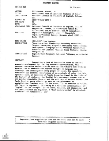
Model 8140 & 8141 Fresh Air VentilatorInstallation and Operations ManualFILTER COVERVENTILATION CONTROLLERINLET COLLAROUTLET COLLARSAFETY INSTRUCTIONSWARNING1. 120 Volts may cause serious injury from electric shock. Disconnect electrical power before starting installation or servicing. Leave powerdisconnected until installation/service is completed.2. Sharp edges may cause serious injury from cuts. Use care when cutting plenum openings and handling duct work.CAUTION1. Read all instructions before beginning installation.2. Improper installation may cause property damage or injury. Installation, service, and maintenance must be performed by a qualified servicetechnician.TABLE OF CONTENTSIntroduction and Compliance Statement . . . . . . . . . . . . . . . . . . . . . . . . . . . . . 2Set Up . . . . . . . . . . . . . . . . . . . . . . . . . . . . . . . . . . . . . . . . . . . . . . . . . . . . . . . . . . . 5Specifications . . . . . . . . . . . . . . . . . . . . . . . . . . . . . . . . . . . . . . . . . . . . . . . . . . . . . 2Test . . . . . . . . . . . . . . . . . . . . . . . . . . . . . . . . . . . . . . . . . . . . . . . . . . . . . . . . . . . . . 6Install Electrical Outlet . . . . . . . . . . . . . . . . . . . . . . . . . . . . . . . . . . . . . . . . . . . . . 2Determine Ventilation Time Setting . . . . . . . . . . . . . . . . . . . . . . . . . . . . . . . . 6Ventilator Location and Orientation . . . . . . . . . . . . . . . . . . . . . . . . . . . . . . . . . 3Start Up and Sequence of Operation . . . . . . . . . . . . . . . . . . . . . . . . . . . . . . . 6Mount the Ventilator . . . . . . . . . . . . . . . . . . . . . . . . . . . . . . . . . . . . . . . . . . . . . . 3Troubleshooting . . . . . . . . . . . . . . . . . . . . . . . . . . . . . . . . . . . . . . . . . . . . . . . . . . . 7Mount Intake Hood . . . . . . . . . . . . . . . . . . . . . . . . . . . . . . . . . . . . . . . . . . . . . . . 4Filter Cleaning . . . . . . . . . . . . . . . . . . . . . . . . . . . . . . . . . . . . . . . . . . . . . . . . . . . . 8Install Ductwork . . . . . . . . . . . . . . . . . . . . . . . . . . . . . . . . . . . . . . . . . . . . . . . . . . 4Limited Warranty . . . . . . . . . . . . . . . . . . . . . . . . . . . . . . . . . . . . . . . . . . . . . . . . . 8Wiring . . . . . . . . . . . . . . . . . . . . . . . . . . . . . . . . . . . . . . . . . . . . . . . . . . . . . . . . . . . 51
INTRODUCTION AND COMPLIANCE STATEMENTThe Model 8140 & 8141 Fresh Air Ventilators are designed to bring in precisely the right amount of outdoor air into today’s efficiently designed homes.Duct the inlet of the ventilator to an outdoor air intake and duct the discharge to the HVAC system, then simply plug the unit in, set the amount ofneeded ventilation and select the desired temperature limits.Temperature limits are set on the control to avoid bringing in outdoor air during the hottest or coldest period of the day. The built in control willautomatically compensate for the ventilation time that is missed by bringing in additional outdoor air during milder periods of the day. Compliancewith the requirements of ASHRAE 62.2-2010 is met as the control adds ventilation time as needed to account for the fractional on-time andeffectiveness of the ventilation schedule. The control will also ensure that ventilation occurs no less than one hour of every four. When properlyinstalled and set, the Model 8140 & 8141 Fresh Air Ventilators will meet the mechanical ventilation requirements of: Energy Star Certified Homes, Version 3 EPA Indoor airPLUS, Version 1 2012 & 2015 International Residential Code (IRC) 2012 & 2015 International Energy Conservation Code (IECC)SPECIFICATIONSTABLE 1 – SPECIFICATIONSExternal StaticPressure ("w.c.)Airflow (CFM)Current (amps)Power (watts)Efficacy 750.6130.4502.620.825.4440.52FIGURE 1 – DIMENSIONS (INCHES)22.1914.0011.9017.19115 VAC1 phase60 Hz27.88Model 8140 shown.Model 8141 has identical dimensions.14.38VoltageINLET: ROUND COLLARFOR 6" DIAMETER DUCT10.44OUTLET: OVAL COLLARFOR 6" DIAMETER DUCT90-2060INSTALL ELECTRICAL OUTLETInstall a standard NEMA 5-15 receptacle suitable for the location, near where the ventilator will be installed. The ventilator comes equipped with a6-foot power cord with a standard 3-prong plug.2
VENTILATOR LOCATION AND ORIENTATIONCAUTIONFIGURE 2 – CLEARANCES FOR SERVICING1. Mount the blower with the lowest, exposed moving parts at least 8 feet (2.4 m)above floor or grade level.2. Mount the blower at least 3.3 feet (1.0 m) from any accessible opening of the duct.Choose a location for the ventilator that is within 6 feet of the outlet into which theventilator will be plugged. Allow space for filter removal and service as shown in FIGURE 2.8140 installations: The ventilator can mounted in any orientation.8141 installations: To ensure proper operation of the backdraft damper on the outlet collar,mount the ventilator with the outlet collar either horizontal as shown below, or angled up.After deciding which orientation the ventilator will be installed, make sure the pivot of thebackdraft damper is located above the centerline of the collar (see FIGURE 3) to ensurethat it closes when the ventilator is off. Remove the outlet collar and rotate it 180 if neededto make sure the backdraft damper functions E 3 – OUTLET COLLAR ORIENTATIONDAMPER PIVOTCENTERLINE OF COLLARCORRECTINCORRECT90-2121MOUNT THE VENTILATOR1. Install the mounting brackets, using the #8 x 1/2" screws supplied, to the side of the housing as shown in FIGURE 4. Use the holes nearest thecovers for mounting to floor joists or hanging from rafters. Use the holes near the bottom of the unit for mounting to a flat wall or ceiling surface.2. Secure the ventilator into joists or a strong platform and screw into place using the #10 x 3/4" screws provided. The ventilator weighsapproximately 25 pounds, so do not secure it into drywall alone.3. Make sure the backdraft damper in the oval outlet collar is positioned so that it will open when the ventilator is on and will close on its own whenthe ventilator is off. If necessary, remove the collar, rotate it 180 and reinstall.FIGURE 4 – MOUNTING BRACKET POSITIONINGAIR FLOWMOUNTED TO THE JOISTMOUNTED TO WALL OR FLOOR JOISTSHUNG FROM THE JOISTMOUNTING BRACKET LOCATIONS90-20603
MOUNT INTAKE HOODInstall a weather tight hood with a bird screen.Cut a hole in the exterior wall that is large enough to fit 6" insulated flexible duct through with minimal compression of the insulation. Pull the ductthrough the hole and attach the flex duct to the collar of the hood. Use metal foil tape or a plastic zip-tie to secure the duct to the collar. Pull theinsulation and vapor barrier over the duct and tape it to the collar.IMPORTANT: The end of the insulation must be sealed to prevent condensation from forming inside the insulation. If a plastic zip-tie is used tosecure the insulation to the hood collar, also tape the end to seal it against condensation problems.Press the hood against the outside wall and secure in place with screws; seal around the perimeter of the hood with caulk.INSTALL DUCTWORKInstall 6" diameter flexible, insulated duct from the round inlet collar of the unit to the intake hood and from the oval outlet collar of the unit to theHVAC system.8140 installations: Duct the outlet of the ventilator to the return side of the HVAC system (refer to FIGURE 5).8141 installations: Duct the outlet of the ventilator to the supply side of the HVAC system. Discharge the ventilation air into a supply plenum toallow for mixing and/or distribution to multiple registers (refer to FIGURE 6).IMPORTANT: The end of the insulation must be sealed to prevent condensation from forming inside the insulation. If a plastic zip-tie is used tosecure the insulation to the hood collar, also tape the end to seal it against condensation problems.FIGURE 5 – MODEL 8140 DUCTING IN UPFLOWAND HORIZONTAL HVAC SYSTEMSFIGURE 6 – MODEL 8141 DUCTING IN UPFLOWAND HORIZONTAL HVAC SYSTEMSTYPICAL ATTIC INSTALLATIONTYPICAL ATTIC INSTALLATIONGABLE END WALL, BAND JOIST, OR PORCH SOFFITGABLE END WALL, BAND JOIST, OR PORCH SOFFITFRESH AIR INTAKE DUCTFRESH AIR INTAKE DUCTFRESH AIRINTAKE HOODWITH SCREENAIHAIR FLOWFRESH AIR VENTILATORVENTILATION CONTROLLERVENTILATION CONTROLLERTYPICAL BASEMENT INSTALLATIONTYPICAL BASEMENT INSTALLATIONFRESH AIRINTAKE HOODWITH SCREENFRESH AIRINTAKE HOODWITH SCREENFRESH AIR INTAKE DUCTVENTILATIONCONTROLLERFRESH AIRVENTILATORHFILTEROUTSIDEWALLFURNACE/AIR HANDLERSUPPLYFRESH AIRINTAKE DUCTAIRAIRFLOWFRESFRESHAIRFRESH AIRVENTILATOR90-20604SUPPLYFRESHESFRAIR FLOWFRESH AIR VENTILATOROUTSIDEWALLFURNACE/AIR HANDLERRFILTERAIRFRESH AIRINTAKE HOODWITH SCREENRETURNMIXING URNACE/AIR HANDLER90-2098
WIRINGThe ventilator control is wired to the HVAC equipment as shown in FIGURE 7 to provide the control with power and to signal the control that theHVAC system is operating. When ventilation is needed but the HVAC system is not running, the ventilator will turn on the HVAC system blower totemper the outdoor air by mixing it with indoor air.1. Disconnect power to the HVAC system prior to wiring to the HVAC system controls.2. Run standard thermostat wire (18-22 AWG) as needed between the ventilator, HVAC system and the disconnect switch.3. Wire as shown in FIGURE 7 or FIGURE 8. Use FIGURE 7 to ensure the controller turns on the HVAC fan when ventilating. Use FIGURE 8 toprevent the controller from turning on the HVAC fan.Optional Disconnect: If the “Minutes per Hour” dial on the ventilator control is not readily accessible, install an optional switch to break the ventilatorcontrol “R” wire as shown in FIGURE 7 or FIGURE 8. Label the switch so as to differentiate it from other switches (“Mechanical Ventilation” label isprovided in the carton with the ventilator).FIGURE 7 – VENTILATOR WIRINGTHERMOSTATRCWYGFIGURE 8 – VENTILATOR WIRING WITHOUT HVAC FAN CONTROLRCWYRVENTILATION CONTROLPOWERRTHERMOSTATWIRE NUT – FIELD SUPPLIEDCNOTUSEDINPUTSODTW GCWYGVENTILATION CONTROLOUTPUTSPOWERVENTRGfGRHVAC SYSTEM CONTROLCWYCNOTUSEDINPUTSODTOUTPUTSW GVENTGfGHVAC SYSTEM CONTROLEXISTING WIREEXISTING WIRENEW WIRENEW WIREOPTIONAL DISCONNECT SWITCH – LABEL“MECHANICAL VENTILATION”OPTIONAL DISCONNECT SWITCH – LABEL“MECHANICAL VENTILATION”DO NOT REMOVE THE PRE-INSTALLED YELLOW WIRES IN THE TERMINALSOF THE CONTROL WHEN WIRING TO THE HVAC SYSTEM.DO NOT REMOVE THE PRE-INSTALLED YELLOW WIRES IN THE TERMINALSOF THE CONTROL WHEN WIRING TO THE HVAC SYSTEM.SET UPThe control can be set up to prevent ventilation during the hottest orcoldest periods of the day. When the outdoor temperature exceeds thehigh value or falls below the low value, ventilation will stop and additionalventilation will be brought in at a later time. See Start Up and Sequenceof Operation section for details.FIGURE 9 – SET TEMPERATURE LIMITS1. Remove the knob then remove the cover to adjust the high/lowtemperature limit (see FIGURE 9).2. Use a small flat head screwdriver to turn the potentiometer to select:A–N o limit, time onlyB – 105 F high limit, 20 F low limitC – 100 F high limit, 30 F low limitD – 95 F high limit, 40 F low limitSelect lockouts to prevent ventilation during only the coldest or warmesttemperatures for your location.R CODT W GVENTGf90-20055
TESTAfter all ducting and wiring is complete, plug in the ventilator, restore power to the HVAC system and make sure the disconnect switch, if installed,is turned on. Turn the thermostat to the OFF mode to ensure that wiring the HVAC system has been done correctly and then return it to the desiredmode after testing. Rotate the Vent Time setting knob to Test/Reset:1. The display will show “- -”, the green “Active Ventilation” LED will blink.2. The ventilator blower will start. For 8140 installations, the integral damper will also open.3. If the ventilator was properly wired to turn on the HVAC unit blower with ventilation, the HVAC blower will turn on.4. After one minute the test will end and the display will blink and show the firmware revision level. Return the knob to the OFF position until thedesired Time Setting is determined.DETERMINE VENTILATION TIME SETTINGCALCULATING AIRFLOW REQUIREMENTTABLE 2 – CFM REQUIRED1. The MINIMUM ventilation requirement is calculated using ASHRAE62.2-2010.House Sq. Ft. ASHRAE Airflow in CFM [House Area in Sq. Ft. x 0.01] [(Number of Bedrooms 1) x 7.5]Number of Bedrooms23456710003540505565701500404555607075 Note: Use ‘Number of Bedrooms 1’ or ‘Number of Occupants’,whichever is larger.200045506065758025005055657080852. TABLE 2 shows the calculated airflow values to the nearest 5 1004500707585901001055000758090951051103. Record the required CFM.MEASURE VENTILATION AIR (CFM) DELIVERY RATE AND SELECT VENT TIME1. Set the Minutes per Hour knob to 60 minutes to run the blower continuously during measurement. Measure the outdoor air flow (CFM) throughthe duct that is bringing in outdoor air. Allow 45 seconds after the ventilator starts before taking the measurement so that the powered damper(Model 8140 only) has opened completely.2. Use the CFM Delivered along with the CFM required to find the Cycle Time per hour setting from TABLE 3. For example if the ventilator isproviding 120 CFM, and the requirement is 70 CFM, set the time to 35 minutes.TABLE 3 – CYCLE TIME SETTING (MINUTES) FOR AIRFLOW DELIVERED VS. AIRFLOW REQUIRED FOR 1 HOUR CYCLECFM Delivered6CFM 5202025253030260151515202025253030
START UP AND SEQUENCE OF OPERATIONSet the Ventilation Time knob to the setting that was determined in the previous section. The ventilator will turn on with the HVAC equipment for theset number of minutes during the one-hour cycle period. If the HVAC equipment does not turn on enough the ventilator will turn on and will turn onthe HVAC system blower, if wired to do so, at the end of the one-hour cycle period to ensure the desired ventilation time is met. The first time it turnson, it will stay on for five minutes to get an accurate air temperature measurement. If the air temperature is within the range that is set (see Set Up),the ventilator will turn on for the amount of time selected within the one-hour cycle period.If the air temperature is outside of the set range, then no additional ventilation will occur for another hour, and the cycle period will automaticallyadjust to four hours. When the ventilator starts again, it will sample the air temperature and if in range, will meet the set amount of ventilation duringthe four-hour cycle period. For example, if the Vent Time was set to 25 minutes per hour and the first time the ventilator came on it measured an airtemperature above the high limit setting, it would turn off after five minutes. The control will automatically change the cycle period to four hours andwork to provide the additional 95 total minutes of ventilation (25 min/hr x 4 hours 100 minutes, minus the five minutes of the first air sampling)during the four-hour cycle period.If the air temperature is still out of range, the control will automatically switch to an 8-hour cycle period, then a 12-hour cycle period and finally a24-hour cycle period. During 8, 12 and 24 hour cycle periods, the total ventilation time increases to compensate for ventilation effectiveness as definedin ASHRAE Standard 62.2-2010. When the cycle period automatically adjusts to 24-hours, the control will turn on ventilation to meet the requirementseven if the temperature is outside of the set limits.TROUBLESHOOTINGFIGURE 10 – MODEL 8140 INTERNAL SCHEMATICRUN CAPACITORMDPST HTWHTML1-BLKBLKBLKBLUBLKCONNECTORSGNDVENTILATION UTPUTSW GVENTGfYLWFIGURE 11 – MODEL 8141 INTERNAL SCHEMATICRUN CAPACITORMBRNBLUCONNECTORBRNREDGRNDPST KBLKGNDGRNCONNECTORSYLWVENTILATION CONTROLYLWPOWERRCNOTUSEDINPUTSODTW GOUTPUTSVENTGfCHASSISGROUNDYLW7
TABLE 4 – TROUBLESHOOTING GUIDESymptomPossible ReasonCorrectionVentilator anddisplay on control donot turn on.No power to the control. Wire the control to the HVAC system as shown in FIGURE 7 or FIGURE 8.E3 shows on display.Sensor inside the control is damaged. Replace control.Air is blowing outof the intake hoodwhen ventilator is off.8141: Backdraft damper is open. Make sure the unit is mounted in the proper orientation – outlet cannot point down.8140: Power damper is stuck open. Remove the oval outlet collar and rotate it 180 so that it closes when the ventilator turns off. Turn on power to the HVAC system. Turn on the “Mechanical Ventilation” switch. Unplug the ventilator (8140 only) and verify that the damper fully closes.FILTER CLEANINGNormally, the fresh air filter will need to be removed and cleaned every six months, but check it after the first three months following installation todetermine if more or less frequent cleaning will be necessary. After cleaning the filter inside the ventilator, clean off the screen at the fresh air intakehood on the outside of the house. The most common cause of reduced ventilation is a clogged air intake hood.To clean the ventilator filter:1. Remove the two screws securing the filter door tothe housing and swing open the door (FIGURE 12).FIGURE 12FIGURE 132. Rotate the plastic filter retainer to release the filterand remove it from the ventilator (FIGURE 13).3. Use water to rinse the filter and shake the excessmoisture off the filter.4. Replace the filter in the ventilator, turn the filterretainer to secure it in the housing, and close andsecure the filter door.REMOVE (2) SCREWSPLASTIC FILTERRETAINER90-2162LIMITED WARRANTYYour Research Products Corporation Aprilaire Fresh Air Ventilator is expressly warranted for five (5) years from date of installation to be free from defects in materials or workmanship.Research Products Corporation’s exclusive obligation under this warranty shall be to supply, without charge, a replacement for any component which is found to be defective within suchfive (5) year period and which is returned not later than thirty (30) days after said five (5) year period by you to either your original supplier or to Research Products Corporation, Madison,Wisconsin 53701, together with the model number and installation date of the dehumidifier.THIS WARRANTY SHALL NOT OBLIGATE RESEARCH PRODUCTS CORPORATION FOR ANY LABOR COSTS AND SHALL NOT APPLY TO DEFECTS IN WORKMANSHIP OR MATERIALSFURNISHED BY YOU INSTALLER AS CONTRASTED TO DEFECTS IN THE VENTILATOR ITSELF.IMPLIED WARRANTIES OF MERCHANTABILITY OR FITNESS FOR A PARTICULAR PURPOSE SHALL BE LIMITED IN DURATION TO THE AFORESAID FIVE YEAR PERIOD. RESEARCH PRODUCTSCORPORATION’S LIABILITY FOR INCIDENTAL OR CONSEQUENTIAL DAMAGES, OTHER THAN DAMAGES FOR PERSONAL INJURIES, RESULTING FROM ANY BREACH OF THE AFORESAIDIMPLIED WARRANTIES OR THE ABOVE LIMITED WARRANTY IS EXPRESSLY EXCLUDED. THIS LIMITED WARRANTY IS VOID IF DEFECTS(S) RESULT FROM FAILURE TO HAVE THIS UNITINSTALLED BY A QUALIFIED HEATING AND AIR CONDITIONING CONTRACTOR. IF THE LIMITED WARRANTY IS VOID DUE TO FAILURE TO USE A QUALIFIED CONTRACTOR, ALL DISCLAIMERSOF IMPLIED WARRANTIES SHALL BE EFFECTIVE UPON INSTALLATION.Some states do not allow limitations on how long an implied warranty lasts or the exclusion or limitation of incidental or consequential damages so the above exclusion or limitations maynot apply to you.This warranty gives you specific legal rights and you may also have other rights which vary from state to state.WARRANTY REGISTRATIONVisit us on-line at www.aprilaire.com to register your Aprilaire product. If you do not have on-line access, please mail a postcard with your name, address, phone number, email address,product purchased, model number, date of purchase and dealer name and address to: Research Products Corporation, P.O. Box 1467, Madison, WI 53701Your warranty registration information will not be sold or shared outside of this company.AprilairePartners.comP.O. Box 1467 Madison, WI 53701-1467800-334-6011 F: 608-257-43578Printed in USA 2017 Aprilaire – A division of Research Products Corporation10011292 B2206783C 4.17
The ventilator control is wired to the HVAC equipment as shown in FIGURE 7 to provide the control with power and to signal the control that the HVAC system is operating . When ventilation is needed but the HVAC system is not running, the ventilator will turn on the HVAC system blower to temper the outdoor air by mixing it with indoor air . 1.