Transcription
Bigelow ExpandableActivity Module (BEAM)ISS Year-OneGerard Valle & Nathan WellsBEAM Project Management andInstrumentation TeamISS R&D Conference,Washington DC19-July-20171
Agenda1. Project overview2. Crew Ingress3. BEAM General Performance Microbial Air & Surface MonitoringDeployment DynamicsThermalMMOD Impact DetectionModal TestRadiation4. Future Plans & Summary5. Team AcknowledgementsBEAM Project2
BEAM project objectivesBEAM on ISS Node 3 Aft Demonstrate a commercial expandable habitat module on ISS in partnership with BigelowAerospace (BA) Increase human-rated inflatable structure Technology Readiness Level (TRL) to 9 Address key elements of NASA’s Space Technology Roadmaps to prepare for future deepspace and surface habitat missions Exploit experience from NASA’s TransHab design and BA’s Genesis I & II pathfinder flightsBEAM animation by NASA/JSC on YouTubehttps://youtu.be/VopaBsuwikkBEAM Project3
Expandable Space Module HistoryEarly 1952Werner Van Braun Space StationConcept with expandable sectionsJuly 12th, 2006Bigelow Aerospace Genesis 1LaunchBEAM ProjectAug. 12th, 1960NASA Launched Echo 1Jan. 30th, 2007Bigelow Aerospace Genesis 2LaunchJan. 25, 1964NASA Launched Echo 21990sNASA Transhab ConceptApril 8th, 2016Bigelow Expandable Activity Module(BEAM) launch to ISS on SpX-84
BEAM Expansion7 hours of deployment in 25 seconds time lapse videoBEAM Project5
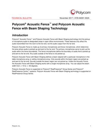
BEAM expanded configurationNot shown: Rip-Stitch Straps (RSS)next to ADSS strutsBEAM IMV DuctAnomalous Depressurization andStabilization System (ADSS) struts (x4)Shear Panel (x8)PCBM to BulkheadTunnel AdapterAft BulkheadBEAM HatchForward BulkheadBEAM ProjectAir Tanks (x8)6
BEAM launched, berthed, anddeployed on ISS BEAM launched on SpX-8 (April 8, 2016), Dragon/BEAM arrived Node 2 (April10th), SSRMS extracted BEAM from Dragon Trunk on Node 2 Nadir, moved it to Node 3,and berthed it on Node 3 Aft port (April 15-16 2016), and fully pressurized on May 28, 2016.BEAM Project7
BEAM Ingress Timeline (Year 1)Ingress1-3DateOperationsJune 6-8, 2016 Outfitted interior, installed sensors, and took microbial air/surface 722-Mar-1728-Apr-1731-May-1720-Jun-17Replaced DIDS battery packs DIDS back to nominal ops, reattached 5 accelerometersto shell with Kapton tape, retrieved exposed RAMs for return in Soyuz 46SPerformed Modal Test; IWIS data not recorded due to bad cable connection,preemptive Kapton-taping of remaining 7 accelerometersRAM install and microbial sampling2nd Modal Test, RAM swap and microbial samplingRAM swap, microbial sampling, accelerometer inspection1st REM shield installed (1.1 mm thick)2nd 3D-printed REM shield (3.3mm thick) installation & new RAMs3rd (final) 3D-printed REM shield (10mm thick) installationIngress #1-#3Ingress #7Ingress #48
BEAM – Microbiological Monitoring Five separate microbiological monitoring sessionsoccurred on: June 8, 2016September 5, 2016October 24, 2016March 22, 2017June 20, 2017 All microbial concentrations from air and surfacesamples were well below the Medical OperationsRequirement Document (MORD) limits. No fungi wereisolated from any samples. No medically significant microorganisms wereisolated from any samples. Future sampling will be performed in August 2017.BEAM Project9
Microbiological Status of BEAM10
BEAM Sensor System OverviewSensorParameterDeploymentData Retrieval Previous UseDistributed ImpactDetection System(DIDS)Detects structuralimpacts to BEAMInstalled pre-launch: 4 transducers on thebulkheadsInstalled on orbit: 12 transducers on thesoft goods sensor boxesRF to SSC(closed hatch)ISS UltrasonicBackground NoiseTest SDTODeploymentDynamics Sensors(DDS)Records accelerationloads during inflationstage3 DDS units and triaxialaccelerometers areinstalled prelaunchUSB to SSC(BEAM ingress)Shuttle WingLeading Edgeaccelerometers andCrew Seat DTOWireless TemperatureSensors (WTS)Monitors temperatureof BEAM surface(IVA)4 WTS units Installedon-orbit (qty 4 RTDchannels each)RF to SSC(closed hatch)Shuttle WirelessStrain GaugeInstrumentationSystemRadiationEnvironment Monitor(REM)Monitors radiationenvironment internalto the BEAM structure2 REM Installed on-orbitUSB to SSC(closed hatch)REM SDTORadiation AreaMonitor (RAM)Passive radiationmonitoring badges6 RAMs Installed onorbitReplaced andreturned to groundevery Soyuz vehiclecycleBEAM Project11
BEAM Sensor System OverviewWTSDIDSREMBEAM ProjectRAMDDS12
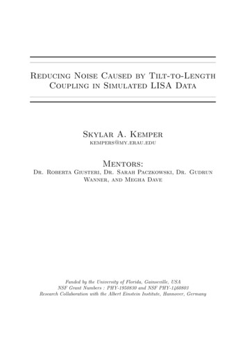
Deployment Dynamic Sensor (DDS)Purpose: Used as a technology demonstration for characterizing the BEAM Module deploymentdynamics with accelerometers on the Aft bulkhead surface.Deployment: Hardware pre-installed prior to launch on Aft bulkhead.Qty 3DeploymentDynamicSensor (DDS)unitsQty 3 triaxialaccelerometersBEAM ProjectQty 8 AirInflationTanksQty 4single axisaccelswithcables forDIDS13
DDS Sensor Results for DeploymentMonitoring The DDS successfully recorded 10 hrs of accelerometer data during theBEAM deployment. Thousands of impulses were measured from the Rip-Stitch Strap (RSS)stitches popping. Max 0.5g peak during initial inflation attempt and max 0.3g during thefinal inflation. No indication of ADSS struts binding or high transient loads on ISS.Inflation Day 1( 2.5 hours)Inflation Day 2(final hour) DDS was also used to support Modal testing inside of BEAM.BEAM Project14
Wireless Temperature Sensor (WTS)Purpose: Used as a technology demonstration for characterizing the BEAM Moduleinternal temperature environment during the 2 yr operational phase.Deployment: Qty 4 Wireless Temp System Kits installed on-orbitOperations: Each WTS data recorder samples 4 Resistive Temperature Device (RTD)channels once per minute and stores to local memory. Data is downloaded wirelessly 1/month to a laptop in Node 3 and then downlinked to the ground.Qty 4 Resistive Temp DeviceSensorQty 1 Extended LifeBattery PackQty 1 Wireless TempSensorQty 1 Battery Pack CableWireless Temp Sys Kit Contents15
BEAM Thermal Performance A total of 16 WTS RTD sensors were installed with tape inside of BEAM. 12 sensors were placed radially along the BEAM inner air barrier and 2 sensors on the Forward and Aftbulkhead surfaced respectively. Approximate locations are shown below. Initial pre-expansion internal temperatures measured by the DDS system were significantly warmer thanpredicted analysis temperatures which was likely due to the folded soft goods layer creating an additionalthermal isolation not modeled. Current model of the Expanded Module tends to under predict the WTS readings. Forward work is requiredto support model validation which will include re-evaluation of Multi-layer Insulation (MLI) blanketperformance, relative isolation of the air barrier from the Debris Protection Assembly (DPA) and higher thanexpected convective heat transfer from Inter-Module Ventilation (IMV) flow. BEAM demonstrated adequate thermal control and condensation prevention with unobstructed ventilationfrom the ISS IMV, nominally at 22.6 ºC and 3.4 m³/min, and ISS atmosphere humidity levels (dew point)from 5.6 to 12.8 ºC (Relative Humidity 33 – 54%)Locations of the 16 WTS sensors (a) BEAM aft bulkhead, (b) air barrier and (c) forward bulkhead** Graphics and data on this slide and the next were provided by the BEAM NASA/JSC Passive Thermal PrincipleInvestigators John Iovine & William Walker16
Temperature (oC)Temperature (oC)BEAM internal WTS Temperature measurementsAll WTSFWDBlkHD17
Temperature (oC)Temperature (oC)BEAM internal WTS Temperature measurementsAftBlkHDAirBarrier18
MM/OD Impact Detection System Overview A pre-flight MM/OD impact detection system feasibility assessmentinvolved performing a variety of tests to ensure the sensor systemcould be installed onto the softgoods material and detect an impactresponse. Tests included: Instrumented tap testing ofDamage Tolerant Test (DTT)inflatable for screening sensorattachment method andstandalone data acquisition testing Pull-testing of sensor attachmentmethod to softgoods material Wiring/DAQ hardware attachmentmechanism inside of module Hypervelocity Impact Testing withrepresentative coupon of softgoodsmaterial w/MM/OD shielding RF communications testing insideof the moduleNASA provided inflatable module for initial sensor systemfeasibility assessment which was NOT part of the BEAM project.19
MM/OD Impact Detection System OverviewHypervelocity Impact (HVI) Testing Accomplishments Demonstrated that the system recorded signal matched accurately with acalibrated data acquisition system at White Sands Test Facility (WSTF). Verified that adhesive attachment method for accelerometers to smoothsurfaces (Bladder) survives HVI impacts. Velocity behavior of the restraint layer was determined (Anisotropic effectsand speed of sound measured). Most of these HVI tests did not reach the restraint layer, and instead werecaptured by the shielding layers. Since the shielding system was resting onthe restraint layer in these tests, the momentum from those impacts didtransfer into the restraint layer via the foam coupling.20
Distributed Impact Detection System OverviewPurpose: Used as a technology demonstration for Micro Meteoroid/Orbital Debris (MM/OD) Impactdetection system of an inflatable structure for BEAM Module during the 2 yr operational phase.Deployment: Qty 4 Accel Transducer cables installed pre-launch to Aft Bulkhead and remaining kittedhardware installed on-orbitOperations: Each DIDS data recorder remains in a low power listening mode until a trigger is recordedabove a set g threshold value and records a 270 ms of 30 KHz sampled data window to internalmemory for each of its independent 4 channels. New trigger status is downlinked daily and raw triggercan be downlinked on an as needed basis.Qty 1 Battery Pack CableQty 1 Antenna MountQty 1 Accelerometer DataRecorderQty 4 Accel TransducerCableQty 1 Extended LifeBattery PackImpact Detection Kit Contents21
Distributed Impact Detection System Overview Detects MM/OD and IVA Events Uses 3 VDC custom designed external Battery Pack, expected operationallife of 2 years. Can store 9999 events on an internal memory card Verified that adhesive attachment method for accelerometers to smoothsurfaces (Bladder) survives HVI impacts. BEAM air barrier had been pre-marked forDIDS/WTS sensor installation locations. Sensor locations were configured to ensuremaximum internal coverage and to monitor preflight identified high risk MM/OD impact probabilitylocations. 12 DIDS piezoelectric accelerometerswere adhered to air barrier via pre-applieddouble-sided transfer tape and Kaptontape by crewNOTE: NOT Actual sensor location!DIDS Sensors locations are for illustration purpose only.DIDS Sensors are Internal toStructure.22
DIDS Sensor Labeling/On-Orbit InstallationB1W1B2W2BB4W4B3W3BEAM Mock-up ViewBEAM Sensor 3D Model ViewNote: Cables attached to inner air barrier with 13/8” dia Velcro dots23
BEAM Impact Detection Performance Overview Initial DIDS operations required engineering to tweak the trigger thresholdparameters to ensure DIDS accelerometers would not falsely trigger due tolow level ISS background noise being injected into the module structure. Crew activity induced loads to structure have been routinely recorded duringprevious crew ingresses in the module DIDS operations had to be adjusted initially to disable an internal amplifierwhich had been left active and was causing increased power consumption.24
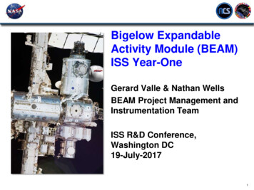
BEAM Impact Detection Performance Overview On GMT 059 (2/28/17) first likely external impact to BEAM was recorded byall three DIDS units monitoring the internal air barrier surfaces. Recordedsignals ranged between 1 - 3 g’s acceleration Signal contained high frequency content Triangulated to have impacted on Zenithside (between Channel 2 & 3) Estimated impact amplitude on restraint layeris 260 g’s based on hypervelocity ground testderived models and data suggests the impact wouldnot have penetrated all the way to the restraint layerEstimated epicenter location of GMT059impact Pictures of estimated impact location were requested via the ISSExternal High Definition Camera (EHDC) P1LOOB, however the cameragave very little Zenith surface viewpoint25
BEAM Impact Detection Performance OverviewDIDS Unit 1119, 2/28/2017, 34DIDS Unit 1119, 2/28/2017, Event 343322DIDS Unit 1119, 2/28/2017, Event 342.0E-021Ch 1 (g)1.5E-020Ch 2 (g)Amplitude (g)0Amplitude (g)Amplitude (g)1-1-1-2-2-3-3Ch 1 (g)1.0E-02Ch 2 (g)Ch 3 (g)Ch 4 (g)05101520Time (msec)255.0E-030305101520Time (msec)2/28/2017 at 14 hrs: 11 mins: 7.189 secs25302/28/2017 at 14 hrs: 11 mins: 7.189 secs0.0E 000322110Ch 3 (g)11.522.533.542/28/2017 at 14 hrs: 11 mins: 7.189 secsZenith DIDS FrequencyResponse0Ch 4 (g)-1-1-2-2-30.5Freq. (KHz)DIDS Unit 1119, 2/23/2017, Event 343Amplitude (g)Amplitude (g)DIDS Unit 1119, 2/28/2017, Event 34-3051015Time (msec)2025302/28/2017 at 14 hrs: 11 mins: 7.189 secs051015Time (msec)2025302/28/2017 at 14 hrs: 11 mins: 7.189 secsZenith DIDS Time History (all 4 channels)26
Modal Test Compare structural modal frequencies of the BEAM on ISS to those measured during BEAMground testing in 1-G (w and w/o MMOD) Measured w/ Internal Wireless Instrumentation System (IWIS) (primary), DIDS, and DDS Targets 1-3 and 8 (BEAM shell); targets 4-7 aft bulkhead. Adjust computer structuralmodels as necessary to better represent BEAM in micro-G on ISS. 5 impulses at each target x 2 series 3 accelerometer axes x 8 targets x 2 series 48 total spectra. Multiple ground and on-orbit modal frequencies wereGround-basedsample of Fistcorrelated based upon accelerometer response,Thump ImpulseForceknowledge of the mode shape from ground tests, andimpulse excitation location and direction. There is greater confidence in lower frequency modes.Frequency Spectrum of Force27
Modal Test- Preliminary Results and Forward Work Preliminary Results Large frequency differences between the on-orbit and ground-based tests forthe first three modes: the first lateral bending modes are 10 – 14% higher andthe first torsion mode is 28% higher on-orbit than in ground tests. Possiblereasons for these differences include the following: MMOD layer interaction with the BEAM restraint layer/wall is different onorbit than under 1-G ground test conditions. Performing ground tests withand without MMOD was valuable for showing this. The spaceflight article and the ground test article have different masses.The first two mode frequencies are higher than in ground-based tests,even without MMOD installed. The ISS interface with BEAM is different from the ground-based test. Forward work Compare modal frequencies of the ISS-attached BEAM loads model to on-orbittest frequencies. Investigate modelling techniques for attaching MMOD layers Investigate mass differences and perform an operational modal analysis (OMA) Perform a similar analysis on the DDS, DIDS, and Camera Microphone data.28
BEAM Radiation Sensors A total of 6 Passive and 2 active radiation sensors were installed inside of BEAM viavelcro. The Radiation Environment Monitors (REMs) couples small radiation sensor withadvanced electronics Consist of a Timepix read-out chip bonded to a 300 µm thick, 2cm2 silicon sensor layer.The Timepix provides on-chip data collection and signal digitization within the footprint of each of the individual pixelsin the 256 by 256 pixel matrixPower/data provided via USB and connect to Space Station Computer laptop in Node 3Provides spectral information (energy deposition as function of particle type and energy) and radiation dose Radiation Area Monitors (RAMs) will come back to ground during nominal ISS Soyuzreturn cycle for data evaluation.Passive Instrumentation (RAM)Active Instrumentation (REM)29
Radiation Performance Radiation (REM) initial results System has been operating without issues since installation (although GUIneeds to be relaunched on a weekly basis due to scheduled laptop reboots. Galactic Cosmic Ray (GCR) dose rate similar to other ISS modules As expected, REMs measured higher trapped field dose rate — e.g., in SouthAtlantic Anomaly (SAA) — inside BEAM than in other ISS modules due tothinner shell and lack of equipment racks in BEAM technology demonstrator Currently an additional test is underway to determine if the particles beingmeasured inside of BEAM are of low energy and if so, can they be effectivelyshielded out with 3D printed plastic hemispheres of various thicknesses (1.1mm,3.3 mm & 10mm. 3D printed hemispheres were printed with the on-board ISS”Made in Space” 3D printer BEAM tech demo data will be used to assess shielding requirements forexpandable habitat modules configured for human exploration missions30
Future Plans & SummaryFuture Plans BEAM was originally planned for a 2 yr operational mission to demonstrateand advance the technology with infrequent human ingresses. ISS management is evaluating options for using BEAM as a long-termhardware stowage module which would require extending the two yearlife and reconfiguration of the wireless instrumentation communication &additional batteries.Summary Overall BEAM has been performing beyond expectations! BEAM will help advance the human rated expandable module to TRL 9 andin the future should be considered as a solution for volume/mass savings infuture planetary and space exploration applications. Use BEAM sensor data and lessons learned to fold into future expandablemodule design Evaluate methods to embed sensors into softgoods material duringfabrication process that would not risk damage to the module duringcompression/expansion phases to reduce crew time for installation.31
Team Acknowledgements The authors of this presentation would like to provide a special thanks to theentire BEAM project team and Bigelow Aerospace. Specifically the authors would like to acknowledge the following people whoprovided BEAM specific performance data: Microbial Monitoring Performance – Ariel Macatangay, William Misek & MelanieSmithDeployment Dynamics & Modal Test Results – Michael GrygierThermal Performance – John Iovine & Dr. William WalkerMM/OD Monitoring Performance – Dr. Eric MadarasRadiation Sensor System & Performance – Dr. Dan Fry and the entire SpaceRadiation Analysis Group (SRAG)32
BackupBEAM Project Why expandables? BEAM education & public outreach BEAM acronyms33
Why Expandables? (1/2)1. Lower launch/ascent volume relative to metallic modules Pro: Reduced size, drag and mass of the launch vehicle (or fairing), or morecargo inside the same fairingCon: Increased complexity for deployment and internal outfittingBEAMMass (w/ PCBM & FSE)PackedInflated 1400 kg ( 3K lb)Inflated/PackedRatio1.0Volume3.6 m316 m34.4Length (w/ FRGF)2.16 m4.01 m1.9Diameter2.36 m3.23 m1.4Pressure014.7 psi-BEAM/Trunk integrationBEAM ProjectPacked BEAM on ISS N3Key benefit of inflatables:launch small, then get bigin space or on the surfaceof the moon or MarsDeployed BEAM34
Why Expandables? (2/2)2. Less mass for the same volume as metallic modules? Maybe. Depends upon mission and design requirements, outfitting, materials, size, etc.Current expandable module experience only at low volumes, not mass-optimizedSmall, mass-optimized metallic modules can be less dense than robust BEAM tech demoLarge expandable module designs potentially offer lower density due to much greaterspecific strength of fabrics vs. metal alloys, though this must be proven in flightMore experience with expandable modules may reduce mass due to reduced factor ofsafety (e.g., ISS requires FoS 4.0 for fabric structures, 2.0 for aluminum) Quick-Look Module Density Comparison300ExpandableDensity Mass/Volume (kg/m3)250MetallicOther ISS modules200150Genesis100BEAM50Kibo JEMSkylab Orbital WorkshopCygnus PCM (enhanced)Leonardo PMMBA330 designTransHab design0050100150200250300350400Volume (m3)BEAM Project35
Education and Public Outreach BEAM full-size mockup in B.9 at JSC(publicly visible on the Space Center Houston Red Tour) NASA Twitter & Facebook posts, Facebook Live, Reddit AMA TV, radio and print media interviews and articles NASA TV Space Station Live interviewAerospace Daily & Defense ReportThe Economist article, “Pump it up, Scotty”, described BEAM as “bouncy castles in space”60 Minutes aired segment with Robert Bigelow and Bigelow Aerospace Online articles Bigelow Aerospace BEAM page: http://bigelowaerospace.com/beam/NASA Feature: http://www.nasa.gov/mission pages/station/news/beam feature.htmlNASA Landing Page: ivity-moduleNASA jan/HQ 13-024 Bigelow ISS Module.htmlSpace News: o-space-station/American Airlines magazine: http://magazines.aa.com/content/beam-meBEAM installation animation by JSC/IGOAL on YouTubehttps://youtu.be/VopaBsuwikkBEAM Project36
BEAM AcronymsABH – Aft BulkheadACBM – Active Common Berthing Mechanism (onISS Node)ADSS – Anomalous Depressurization StabilizationSystemAVV – Ascent Vent ValveBA – Bigelow Aerospace, LLCBEAM – Bigelow Expandable Activity ModuleCCAFS – Cape Canaveral Air Force StationCSA – Canadian Space Agency (provides SSRMS)DCA – Debris Casualty AreaDDS – Deployment Dynamics SensorDIDS – Distributed Impact Detection SystemDPA – Debris Protection AssemblyEOM – End Of MissionEVA – Extravehicular ActivityFBH – Forward BulkheadFRGF – Flight Releasable Grapple FixtureFSE – Flight Support Equipment (by SpaceX)HVI – Hyper Velocity ImpactIMV – Inter-Module VentilationIVA – Intra Vehicular ActivityIWIS – ISS Wireless Instrumentation SystemBEAM ProjectMLI – Multilayer InsulationMM/OD – Micrometeoroid & Orbital DebrisMORD – Medical Operations Requirement DocumentMPEV – Manual Pressure Equalization ValveNSI – NASA Standard Initiators (pyros)ODAR – Orbital Debris Assessment ReportODPO – Orbital Debris Program OfficeORDEM – Orbital Debris Engineering ModelORSAT – Object Reentry Survival Analysis ToolPCBM – Passive Common Berthing Mechanism (onBEAM)PPF – Payload Processing Facility (SpaceX/CCAFS)RAM – Radiation Area Monitor (passive badge)REM – Radiation Environment Monitor (active)RSC – Restraint Strap Cutters (w/ NSI pyros)RSS – Rip-Stitch StrapsSSPF – Space Station Processing Facility (NASA/KSC)SSRMS – Space Station Remote Manipulator SystemSpX – SpaceXWTS – Wireless Temperature Sensor37
BEAM Project BEAM project objectives 3 BEAM on ISS Node 3 Aft Demonstrate a commercial expandable habitat module on ISS in partnership with Bigelow Aerospace (BA) Increase human-rated inflatable structure Technology Readiness Level (TRL) to 9 Address key elements of NASA's Space Technology Roadmaps to prepare for future deep