Transcription
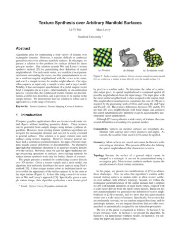
Texture Synthesis over Arbitrary Manifold SurfacesLi-Yi WeiMarc LevoyStanford University AbstractAlgorithms exist for synthesizing a wide variety of textures overrectangular domains. However, it remains difficult to synthesizegeneral textures over arbitrary manifold surfaces. In this paper, wepresent a solution to this problem for surfaces defined by densepolygon meshes. Our solution extends Wei and Levoy’s texturesynthesis method [25] by generalizing their definition of searchneighborhoods. For each mesh vertex, we establish a local parameterization surrounding the vertex, use this parameterization to create a small rectangular neighborhood with the vertex at its center,and search a sample texture for similar neighborhoods. Our algorithm requires as input only a sample texture and a target model.Notably, it does not require specification of a global tangent vectorfield; it computes one as it goes - either randomly or via a relaxationprocess. Despite this, the synthesized texture contains no discontinuities, exhibits low distortion, and is perceived to be similar to thesample texture. We demonstrate that our solution is robust and isapplicable to a wide range of textures.Keywords: Texture Synthesis, Texture Mapping, Curves & Surfaces1IntroductionComputer graphics applications often use textures to decorate virtual objects without modeling geometric details. These texturescan be generated from sample images using texture synthesis algorithms. However, most existing texture synthesis algorithms aredesigned for rectangular domains and can not be easily extendedto general surfaces. One solution is to paste textures onto suchsurfaces using texture mapping. However, because general surfaces lack a continuous parameterization, this type of texture mapping usually causes distortions or discontinuities. An alternativeapproach that minimizes distortion is to generate textures directlyover the surface. However, since we can not apply traditional image processing operations to surfaces, most existing methods forsurface texture synthesis work only for limited classes of textures.This paper presents a method for synthesizing textures directlyover 3D meshes. Given a texture sample and a mesh model, ouralgorithm first uniformly distributes the mesh vertices using Turk’smethod [23]. It then assigns texture colors to individual mesh vertices so that the appearance of the surface appears to be the same asthe input texture (Figure 1). It does this using a non-trivial extension of Wei and Levoy’s approach [25]. Specifically, given a sample texture image, their algorithm synthesizes a new texture pixel Email: {liyiwei levoy}@graphics.stanford.edu(a) Texture(b) Model(c) Synthesis resultFigure 1: Surface texture synthesis. Given a texture sample (a) and a model(b), we synthesize a similar texture directly over the model surface (c).by pixel in a scanline order. To determine the value of a particular output pixel, its spatial neighborhood is compared against allpossible neighborhoods from the input image. The input pixel withthe most similar neighborhood is then assigned to the output pixel.This neighborhood search process constitutes the core of [25] and isinspired by the pioneering work of Efros and Leung [6] and Popatand Picard [19]. The primary differences between [25] and [6, 19]are that [25] uses neighborhoods with fixed shapes and conductsthe search deterministically; therefore it can be accelerated by treestructured vector quantization.Although [25] can synthesize a wide variety of textures, there areseveral difficulties in extending it to general meshes:Connectivity Vertices on meshed surfaces are irregularly distributed, with varying inter-vertex distances and angles. Asa result, the scanline order used in [25] cannot be applied.Geometry Most surfaces are curved and cannot be flattened without cutting or distortion. This presents difficulties for definingthe spatial neighborhoods that characterize textures.Topology Because the surface of a general object cannot bemapped to a rectangle, it can not be parameterized using arectangular grid. Most texture synthesis methods require thespecification of a local texture orientation.In this paper, we present two modifications of [25] to addressthose challenges. First, we relax that algorithm’s scanline order,instead visiting vertices in random order, to allow texture synthesis over surfaces with arbitrary topology. Second, we replace therectangular parameterization of the output domain that is implicitin [25] with tangent directions at each mesh vertex, coupled witha scale factor derived from the mesh vertex density. Based on thisnew parameterization we generalize the definition of search neighborhoods in [25] to meshes, and we show that this generalizationworks over a wide variety of textures. Specifically, for textures thatare moderately isotropic, we use random tangent directions, and foranisotropic textures, we use tangent directions that are either userspecified or automatically assigned by our relaxation procedure.The rest of the paper is organized as follows. In Section 2, wereview previous work. In Section 3, we present the algorithm. InSection 4, we demonstrate synthesis results. In Section 5, we conclude the paper and discuss future work.
2Previous WorkTexture Synthesis: Recent statistical texture synthesis algorithms[11, 22, 4, 25, 6] have achieved success in modeling image textures.Since these algorithms rely on planar grids, it is not clear how theycan be extended to arbitrary surfaces. A different class of methodsgenerate textures through specialized procedures [5]. These techniques produce textures directly over 3D surfaces, so the texturedistortion problem is largely eliminated. However, procedural synthesis is capable of modeling only a limited class of textures.There have been several attempts to extend statistical texturesynthesis to surfaces [7] or 3D volumes [8, 11]. Based on secondorder statistics, [7] relates pairs of mesh vertices via their geodesiccurves. However, second-order statistics are unable to capturesignificant structures that occur in may textures [22]. Volumetricsynthesis [8, 11] avoids this texture distortion. However, thesealgorithms begin from multiple 2D textures and require consistentstatistics over these multiple views; therefore they can model onlytextures without large-scale structures.Texture Mapping: Another body of related work is texture mapping algorithms. However, globally consistent texture mapping[14] is difficult. Often, either distortions or discontinuities, orboth, will be introduced. [17] addressed this problem by patchingthe object with continuously textured triangles. However, thisapproach works only for isotropic textures, and it requires carefulpreparation of input texture triangles obeying specific boundaryconditions. In addition, since it employs relatively large triangles,the approach is less effective for texturing narrow features. Ouralgorithm performs moderately well on semi-anisotropic textures,and it does not require extensive preparation. Another method thathas been suggested is to cover a model with irregular overlappingpatches [20]. This approach works well for some but not allkinds of textures. Also, the discontinuity between adjacenttexture instances are evident if the textured model is seen closeup. The local parameterization method used in [20] inspired theparameterization of the algorithm presented here.Mesh Signal Processing: In principle, we could directly generalize [25] for meshes if there existed a toolkit of general mesh signalprocessing operations. Unfortunately, despite promising recent efforts [10, 21], mesh signal processing still remains largely an openproblem; [21] works only for spheres and [10] is designed for filtering geometries and functions over meshes, not for general meshsignal processing operations such as convolution.3Algorithm(a) 24576 vertices(b) 73728 verticesFigure 2: The retiling vertex density determines the scale for texture synthesis. Textured torus with (a) 24576 vertices and (b) 73728 vertices.Our algorithm uses the same framework as [25]. To make theexposition clear, we first summarize that algorithm in Table 2. Wethen describe our extensions. The core of [25] uses spatial neighborhoods defined on rectangular grids to characterize image textures. In this paper, we generalize the definition of spatial neighborhood so that it can be used for producing textures over general surfaces. We parameterize mesh surfaces using local coordinate orientations defined for each mesh vertex and a scale factorderived from vertex density. We also change the codes for building/reconstructing mesh pyramids, as well as the order for traversing output pixels. For clarity, we mark a at the the beginning ofeach line in Table 2 that needs to be extended or replaced.In the rest of this section, we present our extensions followingthe order in the pseudo-code in Table 2. For easy comparison wealso summarize our new algorithm in Table 3.function Is ImageTextureSynthesis(Ia , Is )1 InitializeColors(Is );2Ga BuildImagePyramid(Ia );3 Gs BuildImagePyramid(Is );4foreach level L from lower to higher resolutions of Gs5 loop through all pixels p of Gs (L) in scanline order6C FindBestMatch(Ga , Gs , L, p);7Gs (L, p) C;8 Is ReconPyramid(Gs );9return Is ;function C FindBestMatch(Ga , Gs , L, p)10 Ns BuildImageNeighborhood(Gs , L, p);11 Nabest null; C null;12 loop through all pixels pi of Ga (L)13Na BuildImageNeighborhood(Ga , L, pi );14if Match(Na , Ns ) Match(Nabest , Ns )15Nabest Na ; C Ga (L, pi );16 return C;Table 2: Pseudocode of [25]. Lines marked with a need to be replacedor extended for synthesizing surface textures.SymbolIaIsMsGaGspipPs (p)N(p)G(L)G(L, p)s, t, n{RxC,k}MeaningInput texture imageOutput texture imageOutput textured meshGaussian pyramid built from IaGaussian pyramid built from Is or MsAn input pixel in Ia or GaAn output pixel/vertex in Is /GsFlattened patches around pNeighborhood around the pixel pLth level of pyramid GPixel p at level G(L)Local texture coordinate system:texture right, texture up, and surface normalneighborhood containing k levels,with sample density RxC pixels at the top levelTable 1: Table of symbols3.1 PreprocessingThe preprocessing stage consists of building multiresolution pyramids and initializing output texture colors (Table 2, line 1 to 3, andTable 3, line 1 to 5). For texturing a surface we add two more stepsto this stage: retiling meshes and assigning a local texture orientation. Let us consider each step in this stage.In Table 2, an image pyramid is built for both the input and output texture image. In the present algorithm, we build the imagepyramid Ga via standard image processing routines, as in [25].However, for output mesh Ms , we construct the correspondingpyramid Gs using mesh simplification algorithms [23]. Note thatat this stage Gs only contains a sequence of simplifications of thegeometry of Ms ; the vertex colors are not yet assigned.After building the mesh pyramid Gs , we retile the surfaces oneach level using Turk’s algorithm [23]. This retiling serves two pur-
function Ms SurfaceTextureSynthesis(Ia , Ms )1Ga BuildImagePyramid(Ia );2 Gs BuildMeshPyramid(Ms );3 RetileMeshes(Gs );4 AssignTextureOrientation(Gs );5 InitializeColor(Gs );6foreach level L from lower to higher resolutions of Gs7 loop through all pixels p of Gs (L) in random order8C FindBestMatch(Ga , Gs , L, p);9Gs (L, p) C;10 Ms ReconMeshPyramid(Gs );11 return Ms ;function C FindBestMatch(Ga , Gs , L, p)12 Ns BuildMeshNeighborhood(Gs , L, p);13 Nabest null; C null;14 loop through all pixels pi of Ga (L)15Na BuildImageNeighborhood(Ga , L, pi );16if Match(Na , Ns ) Match(Nabest , Ns )17Nabest Na ; C Ga (L, pi );18 return C;function Ns BuildMeshNeighborhood(Gs , L, p)19 Ps (p) FlattenLocalPatch(Gs , L, p, s, t, n);20 Ns ResampleNeighborhood(Ps (p));21 return Ns ;Table 3: Pseudocode of our algorithm. Lines marked with a indicateour extensions from the algorithm in Table 2. Note that in our current implementation we only use Gaussian pyramids for meshes; therefore line 10simply extracts the highest resolution from Gs .(a)(b)(c)Figure 3: Orienting textures via relaxation. The red arrows illustrate the sdirections over the mesh vertices: (a) random (b) 2-way symmetry (c) 4-waysymmetry.poses: 1) it uniformly distributes the mesh vertices, and 2) the retiling vertex density, a user-selectable parameter, determines the scaleof the synthesized texture relative to the mesh geometry (Figure 2,see Section 3.3 for details). The retiling progresses from higher tolower resolutions, and we retile each lower resolution mesh withone quarter of the number of vertices of the immediate higher resolution so that the relative sample densities of adjacent pyramid levels relative to one another are compatible between image pyramidGa and mesh pyramid Gs .After retiling, we initialize colors of each level of Gs by assigning random colors from the corresponding level in Ga . This initialization method naturally equalizes the color histograms betweenGa and Gs , thereby improving the resulting texture.The next step is to assign a local coordinate frame for each vertex in the mesh pyramid. This coordinate frame, which determinesthe texture orientation, consists of three orthogonal axes s (textureright), t (texture up), and n (surface normal). These three axes aretacitly assumed to be x, y, z for planar image grids. For generalsurfaces it is usually impossible to assign a globally consistent local orientation (e.g. a sphere). In other words, singularities areunavoidable.Our solution to this problem is to assign the s vectors randomly,at least for isotropic textures. One of the contributions of this paper is the recognition that, in the context of a texture synthesisalgorithm that searches a texture sample for matching neighborhoods, rotating the s and t between the searches conducted at adjacent mesh vertices does not significantly degrade the quality ofthe match found as long as the input texture is reasonably isotropic.(Although isotropic textures are by definition rotationally invariant,this does not immediately imply that we can generate isotropic textures by matching neighborhoods in a rotationally invariant way.)For anisotropic textures this solution does not work. Therefore,we either let the user specify the texture direction as in [20], or weautomatically assign s and t using a relaxation procedure. The goalof this relaxation procedure is to determine the local texture orientation from the directionality of the input texture. That is, givenan n-way symmetric texture, we orient s vectors so that to the extent possible, adjacent s vectors form angles of integer multiples of360n degrees. The relaxation algorithm begins by assigning randomorientations for the lowest resolution level of Gs . It then proceedsfrom lower to higher resolutions of Gs , and at each resolution itfirst initializes s vectors by interpolating from the immediate lowerresolution. Each s is then aligned, iteratively, with respect to itsspatial neighbors (at the current and lower resolutions) so that thesum of individual mis-registration is minimized. The amount ofmis-registration for each s at vertex p is calculated by the followingerror function: 2 φsqp360 E φsqp round( 360 ) n ,q near pnwhere n is the degree of symmetry of the input texture, and φsqpis the angle between sp (s of vertex p) and the projection of sq onthe local coordinate system of vertex p. The idea of using energyminimization for assigning local directions is not new. A similarfunction is used in [18], with the following differences to our approach: (1) we set s and t to be always orthogonal to each other,and (2) we use modular arithmetic in the function so that it favorsdegrees.adjacent s vectors forming angles that are multiples of 360nOur approach is also similar to [12], but we use a slightly different functional, and we do not require the direction fields to alignwith the principle surface curvatures. Examples of orienting 2-wayand 4-way symmetric textures (e.g. stripes and grid) are shown inFigure 3 (b) and (c).3.2 Synthesis OrderThe scanline synthesis order in Table 2 (line 5) cannot be directlyapplied to mesh pyramid Gs since its vertices do not have rectangular connectivity. One solution might be to use the two-passalgorithm for constrained synthesis [25], growing textures spirallyoutward from a seed point. However, there is no natural seed pointfor meshes of arbitrary topology. Surprisingly, we have found thatour algorithm works even if we visit pixels of Gs (L) in random order. Thus, we use a modified two-pass algorithm, as follows. During the first pass, we search the input texture using a neighborhoodthat contains only pixels from the lower resolution pyramid levels(except the lowest resolution where we randomly copy pixels fromthe input image). This pass uses the lower resolution informationto “extrapolate” the higher resolution levels. In the second pass,we use a neighborhood containing pixels from both the current andlower resolution. In both passes, on each level, the neighborhoodsused are symmetric (noncausal). We alternate these two passes foreach level of the output pyramid, and within each pass we simplyvisit the vertices in a random order. In our experience this randomorder works as well as the spiral order used in [25], and it producesslightly worse textures than scanline order only for patterns withscanline dependencies. An example comparing different synthesisorders is shown in Figure 4.
(a) 2186 vertices,4368 faces (b) 8715 vertices,17426 faces(c) 34938 vertices,69868 facesFigure 6: Multi-resolution surface texture synthesis. The synthesis progresses from lower to higher resolutions, and information at lower resolution meshes is used to constrain the growth of textures at higher resolutions.(a)Input(b) Scanline order(c) Random orderFigure 4: Texture synthesis order. (a) Input textures (b) Results withscanline-order synthesis (c) Results with random-order synthesis. For textures without scanline dependencies, we have found that random-orderworks well.dp(a)(b)(c)Figure 5: Mesh neighborhood construction. (a) neighborhood template(b) flattened patch of the mesh (c) neighborhood template embedded in theflattened patch.time until the neighborhood template is fully covered. Trianglesare added in order of increasing distance from the seed triangles,and we determine the position of each newly added vertex usingthe heuristic in [15, Section 3.1.4]. Note that the flattening processcan introduce flipped triangles. If this happens, we stop growingpatches along the direction of flipping. This might in turn produce patches that only partially cover the neighborhood template.In this case, we assign a default color (the average of Ia ) to theuncovered neighborhood pixels. Another solution might be to usesmaller neighborhoods for highly curved areas. However, since anew neighborhood size would require a new VQ codebook [25],this implies building multiple codebooks for tree-structured VQ acceleration. Fortunately, since we only use small neighborhoods,flipping rarely happens.We construct multiresolution neighborhoods in a similar fashion.For each vertex p of pyramid Gs , we first find the correspondingparent faces at lower resolution pyramid levels by intersecting thenormal n of p with the coarse meshes. We project each parent faceorthographically with respect to p’s s, t, n, and we grow a flattenedpatch from the parent face as in the single-resolution case. Thecollection of flattened patches Ps (p) is then resampled to obtainthe multiresolution neighborhood N(p)2 .43.3 Neighborhood ConstructionTable 2 characterizes textures using spatial neighborhoods (line 10and 13). These neighborhoods are planar and coincident with thepyramid grids. For meshes, however, we have to generalize neighborhoods so that they are defined over general surfaces having irregular vertex positions.We build mesh neighborhoods by flattening and resampling themesh locally (Figure 5). To build the neighborhood around an output vertex p, we first select and flatten a set of nearby vertices,henceforth called a patch, so that they fully cover the given neighborhood template (Figure 5 (a,b)). We then resample the flattenedpatch (Figure 5 (c)) by interpolating the color of each neighborhoodpixel (red circles) from the vertex colors of the patch triangle (bluesquares) that contains that pixel. Before flattening,the neighbor hood template is scaled with a constant d 2 A, where A average triangle area of Gs (L), so that the sampling density of theneighborhood and meshvertices are roughly the same1 . Leaving d much larger than 2 A would either introduce aliasing duringresampling or would waste mesh vertices by necessary filtering; ifd were too small, the neighborhood would be poorly representedsince most of its samples would come from the same triangle.The method we use for flattening patches is taken from [20].First, we orthographically project the triangles adjacent to p ontop’s local texture coordinate system. Starting from these seed triangles, we grow the flattened patch by adding triangles one at a1 Wechoose this formula so that if the mesh is a regular planar grid, theneighborhood will be scaled to align exactly with the grid vertices.ResultsOur first example, illustrating the multiresolution synthesispipeline, is shown in Figure 6. The synthesis progresses fromlower to higher resolutions, and information at lower resolutionmeshes is used to constrain the growth of texture patterns at higherresolutions. All synthesis results shown in this paper are generatedwith 4-level Gaussian pyramids, with neighborhood sizes {1x1,1},{3x3,2}, {5x5,2}, {7x7,2} (Table 1), respectively, from lower tohigher resolutions.Texture Orientation: Figure 7 demonstrates the performance ofour algorithm on textures with varying amounts of anisotropy. Themodel we use, a sphere, is the simplest non-developable objectthat has no consistent texture parameterization. Despite this, manytextures are sufficiently isotropic that they can be synthesized usingrandom texture orientations (columns (a) and (b)). For highlyanisotropic textures (column (c)), a random parameterization mayfail, depending on the nature of the textures (column (d)). We canretain the anisotropy by assigning consistent surface orientationseither by hand (column (e) and (f)) or using our iterative relaxationprocedure (column (g)).Model Geometry & Topology: Several textured meshes withdifferent topologies and geometries are shown in Figure 9. Asshown, the algorithm generates textures without discontinuity2 If n of p does not intersect a particular coarse mesh (e.g. it lies on acrease), we simply skip flattening at that level. Instead we assign a defaultcolor to the neighborhood pixels that are not covered, as in the flipping case.
(a)(b)(c)(d)(e)(f)(g)Figure 7: Texture synthesis over a sphere uniformly tesselated with 24576 vertices and 49148 faces. (a) Isotropic textures of size 64x64. (b) Synthesis withrandom orientations. (c) Anisotropic textures of size 64x64. (d) Synthesis with random orientations. (e) Synthesis with s and t vectors at each vertex parallelto longitude and altitude of the sphere. (f) The polar views of (e), showing the singularity. (g) Synthesis with orientation computed by our relaxation procedure(Section 3.1). The top two textures are generated using 2-way symmetry (Figure 3 (b)), while the bottom one is generated using 4-way symmetry (Figure 3 (c)).(a)(b)Figure 8: Different views around the ears of the textured bunny in Figure 1.(a) back view. (b) top view.across a variety of surface geometries and topologies, even acrossfine features such as the bunny ear (Figure 8). The algorithm canalso be used to synthesize surface attributes other than colors suchas displacement maps (the mannequin model in Figure 9).Computation Time: By using an efficient data structure formeshes (we use the quad-edge data structure [9], although otherapproaches are possible), we achieve linear time complexity withrespect to the neighborhood sizes for both the flattening and resampling operations. In our C implementation running on a 450MHz Pentium II machine, the timing for texturing the sphere inFigure 7 is as follows: relaxation (30 iterations) - 85 seconds, synthesis with exhaustive search - 695 seconds, and synthesis with treestructured VQ acceleration - 82 seconds.5Conclusions and Future WorkWe have presented extensions of [25] that permit us to synthesizetextures over surfaces of arbitrary topology, beginning with a rectangular texture sample. The most significant of these extensionsare that we traverse output vertices in a random order, thus allowingtexture synthesis for general meshes, and we parameterize mesheswith a user-selectable scale factor and local tangent directions ateach mesh vertex. We define mesh neighborhoods based on this parameterization, and we show that this approach works over a varietyof textures. Specifically, we synthesize isotropic textures with random local orientations, while generating anisotropic textures withlocal directions that are either hand-specified or automatically determined by our relaxation procedure.Our approach has several limitations. Since it is an extention of[25], it only works for texture images; therefore it is not as generalas [20] which can paste any image onto a mesh model. Howeverfor the class of textures that can be modeled by [25], our approachusually produces continuous surface textures with less blocky repetitions. In addition, for textures that are not well modeled by [25],we could generate better results by combining our surface-synthesisframework with other improved texture synthesis algorithms suchas [1]. Finally, our representation of the output as a retiled polygonal mesh with vertex colors may not be desirable in cases where wewould like to preserve the original mesh geometry. In such casesthe output can be mapped back onto the original model in a postprocess by resampling, such as in [3].In concurrent work, Turk has developed a similar approach forsynthesizing textures over surfaces [24]. The primary differencesbetween [24] and our work are as follows: (1) we have used randomas well as symmetric vector fields for certain textures, whereas [24]always creates a smooth vector field, (2) instead of a sweeping order, we visit mesh vertices in random order, (3) the two approachesuse different methods for constructing mesh neighborhoods; [24]uses surface marching while we use flattening and resampling, and(4) we do not enforce a explicit parent-child relationship betweenmesh vertices at adjacent resolutions.We envision several possible directions for future work. Although our relaxation procedure can assign reasonable local orientations for many anisotropic but symmetric textures, it remains anopen problem for which symmetry classes local orientations can beassigned in this way. Another future direction is to use a variant ofour algorithm to transfer textures (either colors or displacements)from one scanned model [13] to another mesh model. This couldbe done by replacing the input image Ia Table 3 with an input mesh
Figure 9: Surface texture synthesis over different models. The small rectangular patches (size 64x64) are the input textures, and to their right are synthesisresults. In all examples the textures are used to modulate the colors, except the last one where the texture is used for displacement mapping. Texture orientationand mesh sizes: teapot (no symmetry, 256155 vertices, 512279 faces), mechanical part (2-way symmetry, 49180 vertices, 98368 faces), knot (random, 49154vertices, 98308 faces), horse (4-way symmetry, 48917 vertices, 97827 faces), cat (2-way symmetry, 50015 vertices, 100026 faces), and mannequin (no symmetry,256003 vertices, 512002 faces).model, and changing line 1 and 15 in Table 3 to BuildMeshPyramid and BuildMeshNeighborhood, respectively. Finally, our definition of mesh neighborhoods might be applicable to other signalprocessing operations over meshes such as convolution, filtering,and pattern matching.AcknowledgmentsWe would like to thank Greg Turk for his mesh retiling code and theanonymous reviewers for their comments. The texture thumbnailsshown in the paper were acquired from the Brodatz texture album[2], MIT Vision Texture [16], Jeremy De Bonet’s webpage, andother anonymous websites. Polygonal models were acquired fromHugues Hoppe’s webpage, the Large Geometric Models Archive atGeorgia Tech, and the OpenInventor model database. This researchwas supported by Intel, Interval, and Sony under the Stanford Immersive Television Project.References[1] M. Ashikhmin. Synthesizing natural textures. 2001 ACM Symposium on Interactive 3D Graphics, pages 217–226, March 2001. ISBN 1-58113-292-1.[2] P. Brodatz. Textures: A Photographic Album for Artists and Designers. Dover,New York, 1966.[3] P. Cignoni, C. Montani, C. Rocchini, R. Scopigno, and M. Tarini. Preservingattribute values on simplified meshes by resampling detail textures. The VisualComputer, 15(10):519–539, 1999. ISSN 0178-2789.[4] J. S. De Bonet. Multiresolution sampling procedure for analysis and synthesis oftexture images. In T. Whitted, editor, SIGGRAPH 97 Conference Proceedings,Annual Conference Series, pages 361–368. ACM SIGGRAPH, Addison Wesley,Aug. 1997.[5] D. S. Ebert, F. K. Musgrave, D. Peachey, K. Perlin, and S. Worley. Texturing andModeling: A Procedural Approach. Morgan Kaufmann Publishers, 1998.[6] A. Efros and T. Leung. Texture synthesis by non-parametric sampling. In International Conference on Computer Vision, volume 2, pages 1033–8, Sep 1999.[7] A. Gagalowicz and Song-Di-Ma. Model driven synthesis of natural textures for3-D scenes. Computers and Graphics, 10(2):161–170, 1986.[8] D. Ghazanfarpour and J.
In Table 2, an image pyramid is built for both the input and out-put texture image. In the present algorithm, we build the image pyramid G a via standard image processing routines, as in [25]. However, for output mesh M s, we construct the corresponding pyramid G s using mesh simplification algorithms [23]. Note that at this stage G