Transcription
AquaForce 30XA080-501Air-Cooled Liquid ChillersControls, Start-Up, Operation, Serviceand TroubleshootingCONTENTSPageCONTENTS . . . . . . . . . . . . . . . . . . . . . . . . . . . . . . . . . . 1SAFETY CONSIDERATIONS . . . . . . . . . . . . . . . . . . . . 2GENERAL . . . . . . . . . . . . . . . . . . . . . . . . . . . . . . . . . . . 3Conventions Used in This Manual . . . . . . . . . . . . . . . 3Display Module Usage . . . . . . . . . . . . . . . . . . . . . . . . . 3CONTROLS . . . . . . . . . . . . . . . . . . . . . . . . . . . . . . . . . . 8General . . . . . . . . . . . . . . . . . . . . . . . . . . . . . . . . . . . . . 8Main Base Board (MBB) . . . . . . . . . . . . . . . . . . . . . . . 8Compressor Protection Module (CPM) . . . . . . . . . . . 8Electronic Expansion Valve (EXV) Board . . . . . . . . 13Fan Boards . . . . . . . . . . . . . . . . . . . . . . . . . . . . . . . . . 15Enable-Off-Remote Contact Switch (SW1) . . . . . . . 17Emergency On/Off Switch (SW2) . . . . . . . . . . . . . . . 17Hand-Off-Auto Switch (HOA) . . . . . . . . . . . . . . . . . . 17Energy Management Module (EMM). . . . . . . . . . . . . 17Hot Gas Bypass/Pump Board . . . . . . . . . . . . . . . . . . 17Local Equipment Network . . . . . . . . . . . . . . . . . . . . . 19Board Addresses . . . . . . . . . . . . . . . . . . . . . . . . . . . . 19Carrier Controller Display . . . . . . . . . . . . . . . . . . . . . 19Control Module Communication. . . . . . . . . . . . . . . . 20Carrier Comfort Network (CCN) Interface . . . . . . . 20Remote Alarm and Alert Relays . . . . . . . . . . . . . . . . 21CONFIGURATION. . . . . . . . . . . . . . . . . . . . . . . . . . . . 21Carrier Controller Operation Configuration Tables . . 21Machine Control Methods . . . . . . . . . . . . . . . . . . . . . 23Machine On/Off Control. . . . . . . . . . . . . . . . . . . . . . . 23Fluid Set Point Control Location . . . . . . . . . . . . . . . 27Cooling Set Point Selection . . . . . . . . . . . . . . . . . . . 28Chilled Water Fluid Type Selection . . . . . . . . . . . . . 29Cooler Pump Control . . . . . . . . . . . . . . . . . . . . . . . . . 30Machine Start Delay . . . . . . . . . . . . . . . . . . . . . . . . . . 32Circuit/Compressor Staging and Loading . . . . . . . . 32Minimum Load Control . . . . . . . . . . . . . . . . . . . . . . . 34Dual Chiller Control . . . . . . . . . . . . . . . . . . . . . . . . . . 34Night Time/Low Noise Operation . . . . . . . . . . . . . . . 39Ramp Loading . . . . . . . . . . . . . . . . . . . . . . . . . . . . . . 39Temperature Reset. . . . . . . . . . . . . . . . . . . . . . . . . . . 39Demand Limit . . . . . . . . . . . . . . . . . . . . . . . . . . . . . . . 43Ice Storage Operation . . . . . . . . . . . . . . . . . . . . . . . . 47Broadcast Configuration . . . . . . . . . . . . . . . . . . . . . . 47Alarm Control . . . . . . . . . . . . . . . . . . . . . . . . . . . . . . . 47Daylight Saving Time Configuration . . . . . . . . . . . . 48Capacity Control Overrides. . . . . . . . . . . . . . . . . . . . 49Head Pressure Control . . . . . . . . . . . . . . . . . . . . . . . 51PRE-START-UP . . . . . . . . . . . . . . . . . . . . . . . . . . . . . .60System Check . . . . . . . . . . . . . . . . . . . . . . . . . . . . . . . 60START-UP . . . . . . . . . . . . . . . . . . . . . . . . . . . . . . . . . .60Actual Start-Up . . . . . . . . . . . . . . . . . . . . . . . . . . . . . .60Operating Limitations. . . . . . . . . . . . . . . . . . . . . . . . . 61OPERATION. . . . . . . . . . . . . . . . . . . . . . . . . . . . . . . . .70Sequence of Operation. . . . . . . . . . . . . . . . . . . . . . . .70Dual Chiller Sequence of Operation . . . . . . . . . . . . .71Operating Modes. . . . . . . . . . . . . . . . . . . . . . . . . . . . .71Sensors . . . . . . . . . . . . . . . . . . . . . . . . . . . . . . . . . . . .74SERVICE . . . . . . . . . . . . . . . . . . . . . . . . . . . . . . . . . . .78Economizer Assembly . . . . . . . . . . . . . . . . . . . . . . . .78Electronic Expansion Valve (EXV) . . . . . . . . . . . . . .78Compressor Assembly. . . . . . . . . . . . . . . . . . . . . . . .82Cooler Service. . . . . . . . . . . . . . . . . . . . . . . . . . . . . . . 84Flooded Cooler Units . . . . . . . . . . . . . . . . . . . . . . . . .84DX Cooler Units. . . . . . . . . . . . . . . . . . . . . . . . . . . . . .87DX Cooler and Flooded Cooler Units . . . . . . . . . . . .90Condenser Coil Maintenance and CleaningRecommendations . . . . . . . . . . . . . . . . . . . . . . . . . 90MCHX Condenser Coil Maintenance and CleaningRecommendations . . . . . . . . . . . . . . . . . . . . . . . . . 90RTPF Condenser Coil Maintenance and CleaningRecommendations . . . . . . . . . . . . . . . . . . . . . . . . . 90Condenser Fans . . . . . . . . . . . . . . . . . . . . . . . . . . . . .91Refrigerant Circuit . . . . . . . . . . . . . . . . . . . . . . . . . . .91Safety Devices . . . . . . . . . . . . . . . . . . . . . . . . . . . . . .92Relief Devices . . . . . . . . . . . . . . . . . . . . . . . . . . . . . . . 92MAINTENANCE . . . . . . . . . . . . . . . . . . . . . . . . . . . . . .93Recommended Maintenance Schedule . . . . . . . . . .93TROUBLESHOOTING . . . . . . . . . . . . . . . . . . . . . . . . .93Alarms and Alerts . . . . . . . . . . . . . . . . . . . . . . . . . . . .93Service Test. . . . . . . . . . . . . . . . . . . . . . . . . . . . . . . .109APPENDIX A — CARRIER CONTROLLER DISPLAYTABLES . . . . . . . . . . . . . . . . . . . . . . . . . . . . . . . . .118APPENDIX B — NAVIGATOR TABLES. . . . . . .APPENDIX C — CCN TABLES . . . . . . . . . . . . . .APPENDIX D — 30XA080-501 CPMDIP SWITCH ADDRESSES . . . . . . . . . . . . . . .APPENDIX E — PIPING/INSTRUMENTATION .APPENDIX F — MAINTENANCE SUMMARYAND LOG SHEETS. . . . . . . . . . . . . . . . . . . . . .APPENDIX G — BACNET COMMUNICATION .APPENDIX H — COOLER HEATER SENSORSET POINT . . . . . . . . . . . . . . . . . . . . . . . . . . . .135150168174180183193INDEX . . . . . . . . . . . . . . . . . . . . . . . . . . . . . . . . . . . . .194START-UP CHECKLISTFOR 30XA LIQUID CHILLERS . . . . . . . . . . . . . .CL-1Manufacturer reserves the right to discontinue, or change at any time, specifications or designs without notice and without incurring obligations.Catalog No. 04-53300210-01Printed in U.S.A.Form 30XA-6TPg 13-21Replaces: 30XA-5T
SAFETY CONSIDERATIONSWARNINGInstallation and servicing of air-conditioning equipment can behazardous due to system pressure and electrical components. Onlytrained and qualified service personnel should install, repair, orservice air-conditioning equipment.Untrained personnel can perform basic maintenance functions ofcleaning coils and filters and replacing filters. All other operationsshould be performed by trained service personnel. When workingon air-conditioning equipment, observe precautions in theliterature, tags and labels attached to the unit, and other safetyprecautions that may apply.Follow all safety codes, including ANSI (American NationalStandards Institute) Z223.1. Wear safety glasses and work gloves.Use quenching cloth for unbrazing operations. Have fireextinguisher available for all brazing operations.It is important to recognize safety information. This is the safetyalert symbol. When you see this symbol on the unit and ininstructions or manuals, be alert to the potential for personalinjury.Understand the signal words DANGER, WARNING,CAUTION, and NOTE. These words are used with the safetyalert symbol. DANGER identifies the most serious hazards whichwill result in severe personal injury or death. WARNING signifieshazards which could result in personal injury or death. CAUTIONis used to identify unsafe practices, which may result in minorpersonal injury or product and property damage. NOTE is used tohighlight suggestions which will result in enhanced installation,reliability, or operation.Electrical shock can cause personal injury and death. Shut offall power to this equipment during installation. There may bemore than one disconnect switch. Tag all disconnect locationsto alert others not to restore power until work is completed.DANGERDO NOT USE TORCH to remove any component. Systemcontains oil and refrigerant under pressure.To remove a component, wear protective gloves and goggles and proceed as follows:a. Shut off electrical power to unit.b. Recover refrigerant to relieve all pressure from systemusing both high-pressure and low pressure ports.c. Traces of vapor should be displaced with nitrogen andthe work area should be well ventilated. Refrigerant incontact with an open flame produces toxic gases.d. Cut component connection tubing with tubing cutter andremove component from unit. Use a pan to catch any oilthat may come out of the lines and as a gage for howmuch oil to add to the system.e. Carefully un-sweat remaining tubing stubs when necessary. Oil can ignite when exposed to torch flame.Failure to follow these procedures may result in personalinjury or death.DANGERCAUTIONFailure to follow these procedures will result in severepersonal injury or death.DO NOT VENT refrigerant relief devices within a building.Outlet from rupture disc or relief valve must be ventedoutdoors in accordance with the latest edition of ANSI/ASHRAE 15 (American National Standards Institute/American Society of Heating, Refrigerating and AirConditioning Engineers) (Safety Code for MechanicalRefrigeration). The accumulation of refrigerant in anenclosed space can displace oxygen and cause asphyxiation.PROVIDE adequate ventilation in accordance with ANSI/ASHRAE 15, especially for enclosed and low overheadspaces. Inhalation of high concentrations of vapor is harmfuland may cause heart irregularities, unconsciousness, or death.Intentional misuse can be fatal. Vapor is heavier than air andreduces the amount of oxygen available for breathing. Productcauses eye and skin irritation. Decomposition products arehazardous.DO NOT USE OXYGEN to purge lines or to pressurize amachine for any purpose. Oxygen gas reacts violently with oil,grease, and other common substances.DO NOT USE air to leak test. Use only refrigerant or drynitrogen.NEVER EXCEED specified test pressures. VERIFY theallowable test pressure by checking the instruction literatureand the design pressures on the equipment nameplate.DO NOT VALVE OFF any safety device.BE SURE that all pressure relief devices are properly installedand functioning before operating any machine.RISK OF INJURY OR DEATH by electrocution. Highvoltage is present on motor leads even though the motor is notrunning when a solid state or inside-delta mechanical starter isused. Open the power supply disconnect before touchingmotor leads or terminals.UNIT DAMAGE HAZARDThis unit uses a microprocessor-based electronic controlsystem. Do not use jumpers or other tools to short out components or to bypass or otherwise depart from recommended procedures. Any short-to-ground of the control board oraccompanying wiring may destroy the electronic modulesor electrical components.CAUTIONTo prevent potential damage to heat exchanger tubes, always run fluid through heat exchanger when adding or removing refrigerant charge. Use appropriate antifreeze solutions in cooler fluid loop to prevent the freezing of heat exchanger or interconnecting piping when the equipment isexposed to temperatures below 32 F (0 C). Proof of flowswitch is factory installed on all models. Do NOT removepower from this chiller during winter shut down periodswithout taking precaution to remove all water from heat exchanger. Failure to properly protect the system from freezing may constitute abuse and may void warranty.CAUTIONCompressors require specific rotation. Test condenserfan(s) first to ensure proper phasing. Swap any two incoming power leads to correct condenser fan rotation beforestarting compressors. Operating the unit without testing thecondenser fan(s) for proper phasing could result in equipment damage.2
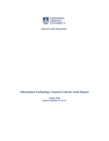
screen for display and user configuration, a Start/Stop button, andan Alarm Indicator LED (light-emitting diode). See Fig. 1.CAUTIONLCD TOUCH SCREENDO NOT re-use compressor oil or any oil that has been exposed to the atmosphere. Dispose of oil per local codes andregulations. DO NOT leave refrigerant system open to airany longer than the actual time required to service theequipment. Seal circuits being serviced and charge with drynitrogen to prevent oil contamination when timely repairscannot be completed. Failure to follow these proceduresmay result in damage to equipment.ALARMINDICATORLIGHTGENERALThis publication contains Controls, Operation, Start-Up, Service and Troubleshooting information for the 30XA080-501air-cooled liquid chillers with electronic controls. The 30XAchillers are equipped with ComfortLink controls and electronicexpansion valves. The AquaForce 30XA chillers offer twodifferent user interface devices, the Carrier Controller displayand the Navigator display.START-STOPBUTTONFig. 1 — Carrier Controller DisplayThe Carrier Controller display can be used to access variousCarrier Comfort Network devices. For operation under thesecircumstances, contact your Carrier representative.Operation of the Carrier Controller display is driven from thedisplays on the touch screen. The Carrier Controller displayuses the following screen “buttons” to allow the user to operatethe display and navigate within and between screens.“BACK” Returns to the next higher screen in thehierarchy.“HOME” Displays the Default Group Display screenfor Carrier Controller display. The Default Screen is auser-configured display of up to 9 points on each of 8 screens.This allows for quick access to various, frequently viewedpoints, without navigating through the Main Menu structure.This button is available at all menu levels and returns the userto the first Default Group Display screen.“MAIN MENU” Displays the Main Menu screen. Thisallows access for viewing and configuration, wherepossible, of all points supported by the controller. This includespoints such as set point and operational configuration. Thisbutton is available at all menu levels and returns the user to theMain Menu screen.“PREVIOUS” In a group of sequential screens of thesame type, pressing this button moves the user to thenext earlier screen in the group.“NEXT” In a group of sequential screens of the sametype, pressing this button advances the user to the nextscreen in the group.“OK” Agrees with, or says “yes” to a prompt and performs the appropriate processing.“NO” Rejects, or says “no” to a prompt and performsthe appropriate processing.“CANCEL” Terminates an ongoing action and returnsto the current screen without any other processing.“CLEAR DATA” Clears the data value in a data entrydialog box. This button is used to clear incorrect data.“RESET DATA” Zeros the data value in a data entrydialog box.“ADD” Adds the active point to a Group Displayscreen.“REMOVE” Deletes a point from a Group Displayscreen.“INCREASE” Modifies the value of a field within itsdefined limits or “SCROLL UP” and shifts the screenview up by one item.Conventions Used in This ManualThe following conventions for discussing configuration pointsfor the Navigator module and Carrier Controller display will beused in this manual.Point names for the Carrier Controller display will be shown inbold. See Appendix A for a complete list of point names. Itemnames for the Navigator module will be shown in bold italics.See Appendix B for the complete path name preceding the itemname. The point and item names in Appendices A and B willbe listed in alphabetical order and the path name for each willbe written with the mode name first, then any sub-modes, eachseparated by an arrow symbol ( .This path name will show the user how to navigate through theNavigator module or the Carrier Controller display to reach thedesired configuration. The user would scroll through the modesand sub-modes using theandkeys on the Navigatordisplay. For the Carrier Controller display, the user would simply touch the menu item on the screen. The arrow symbol inthe path name represents pressing ENTER to move into thenext level of the menu structure for the Navigator module, ortouching the menu item on the screen for the Carrier Controllerdisplay.When a value is included as part of the point name, it will beshown after the point name after an equals sign. If the value represents a configuration setting, an explanation will be shown in parentheses after the value. The Carrier Controller name will beshown first with the Navigator name following. As an example,(Circuit Loading Sequence 1 (A Lead), LLCS Cir A leads).Press the ESCAPE and ENTER keys simultaneously on theNavigator module to display an expanded text description of thepoint name or value. The expanded description is shown in theNavigator display tables (Appendix B) but will not be shown withthe path names in text. The Carrier Controller display will show anexpanded description of the point name. To view the expandedpoint name for the Carrier Controller display go to Appendix A.The Carrier Controller display configures the unit via the CCN(Carrier Comfort Network ) Tables, which are located inAppendix C of this manual.Display Module UsageCARRIER CONTROLLER DISPLAYThe Carrier Controller display is the standard user interface for theAquaForce 30XA chillers with the ComfortLink control system.The display includes a large LCD (liquid crystal display) touch3
“DECREASE” Modifies the value of a field within itsdefined limits or “SCROLL DOWN” and shifts thescreen view down by one item.“PAGE DOWN” If the current table or list has moredata than will fit on the screen, pressing this buttonwill replace the items currently on the screen with the nextgroup of items.“PAGE UP” If the current table or list has more datathan will fit on the screen, pressing this button will replace the items currently on the screen with the previous groupof items.“FORCE” Begins the process of forcing or overridingthe value of a point.“AUTO” Begins the process of removing a force froma point.“MODIFY” Begins the process of modifying a configuration value.“ALARM INDICATOR LIGHT” An LED alarm indicator light is activated when a new alarm condition occurs. The alarm indicator light, located on the rightside of the display, remains activated until it is manually resetusing the Reset button on the Main menu.“START/STOP BUTTON” The Carrier Controller display includes an equipment Start/Stop Button that enablesthe user to start or stop the chiller from the display. SeeEnable-Off-Remote Contact Switch (SW1) on page 17 for additional information.Several items are password protected. When required, a Password dialog box will be displayed for field input of the password. The default password is 3333. The password can bechanged if desired.COMMAND REJECTED will be displayed if the unit is in anON state and a configuration change is attempted. Place theunit in the OFF state before making a configuration change.Power-Up DisplayWhen the Carrier Controller display is powered up, it displaysan initialization progress bar and attaches (initiates communication) to the Main Base Board. The Carrier Controller displaythen shows that controller’s default Group Display screen. SeeFig. 2. This is a user-configured display screen with up to 9points on 8 separate screens. For more information on addingor removing points from the Group Display screen, see theGroup Display Screens section on page 5.Touch any of the screen point buttons and the Point Data Dialog box will be displayed with expanded information. In theexample shown below, the CTRL PNT button in the bottomleft corner was selected. See Fig. 2 and 3.To exit the box, press.Main Menu DisplayThe default screen for the Carrier Controller controller is theGroup Display screen. To access the Main Menu, press thebutton. The screen shown in Fig. 4 will be displayed. Selectinga button will display the screens associated with that category.The user can also access the login screen from the Main Menuif needed.Carrier Controller Menu StructureThe user can navigate through the Carrier Controller displayscreens by selecting the buttons that appear on the screen.When a button is selected, either a sub-menu or a list of pointnames and values will be shown. Submenus will display a listof associated point names. See Fig. 5 for the Carrier Controllermenu structure.If the list of point names and values are shown, the top line ofthe display is the table name. The line and total line counter isdisplayed in the upper right corner of the display. Selecting anitem will cause a Point Data dialog box to appear.Setup Menu ScreenThe Setup Menu screen, shown in Fig. 6, is accessed by pressing the Setup button from the Main Menu. This configurationallows the user to configure the basic operation and look of thedisplay. Table 1 summarizes the Setup Menu functions.Fig. 2 — Group Display ScreenFig. 3 — Point Data Dialog BoxFig. 4 — Main Menu DisplaySetting the Time and DateThe ComfortLink control has a time and date function. Thiscan be useful for diagnostics to determine when alarms occur.The control is factory configured for the proper date and is setfor the Eastern Time Zone. The date and time zone must bechecked and corrected if necessary, to allow the machine tofunction on an internal time schedule and to display a proper4
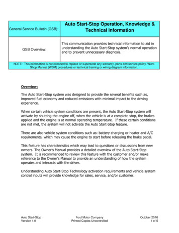
time and date stamp for alarms. The time and date is displayedon the Group Display Screen.To change the Time and Date, press theMain Menu button.SelectTime. On the display, a day and date box with atime box will be shown. To change the day and date, press theday and date box. A calendar will be displayed. If the correctmonth is displayed, touch the correct date. If the wrong monthis displayed, use theorto change to the correct monthand select the correct date. The date will highlighted. Pressto accept the change. The previous screen will be displayed with the corrected day and date shown. To correct thetime, use theoron the left to change the hour. Use theoron the left to change the minutes. Continuouslytouching theorwill sequence the numbers. The time isshown in a 24-hour format. To accept the changes, press theorbuttons. A “Save” dialog box is displayed with thewords, “Do you wish to save changes?” Pressto acceptthe changes.Group Display ScreensThe Carrier Controller display supports up to eight Group Display screens. Group Display screens show status informationalong the top of the screens and nine buttons that display ninepoint names and point values that are chosen by the user. AllGroup Display screen points are user configurable. The bottomline of the screen contains navigation buttons that can be usedto move between the Group Display screens.Pressing a point button will show that point’s Point Data dialogbox. See Fig. 2 and 3. This box contains buttons that removethe point from the group display and apply or remove a force(point override). When touching any button in the displayscreen, the button will be outlined to acknowledge input. Theremay be a delay in response to input, but if the button is outlined, do NOT press any other button until the previous inputhas been processed.If there is a communication failure with the MBB (Main BaseBoard), all point buttons will be displayed in inverse video andthe message Communication Failure will be displayed in thetop left line of the screen.Default Group DesignationThe default group is the first of the 8 Group Display screens.This is the default screen of the display. Information on thisscreen as well as the other 7 screens can be user-modified tomeet the needs of the site.To Add a Point To a Group DisplayFrom the Main Menu, press the desired menu button (Status,Setpoint, Service, Maint, or Config) and, if necessary, the submenu button to access the point to be added. Press the point button to show the source point’s Point Data dialog box. See Fig. 3.From the Point Data dialog box, press the ADD button. The display will show the last Group Display accessed. Use the navigation buttons to access the destination Group Display. Press anexisting point button or a blank button to update the highlightedbutton with the source point’s name. Press to add the highlightedpoint to the group and return to the table display.Generic ControllerDefault ScreenGroup DisplayScreensMain M enuScreenTable ListScreenScheduleList ScreenPOC TableList ScreenAlarm Hist oryList ScreenTime Sc heduleScreenAlarm ResetDialogTime & DateScreenPoint DataDialogRemoveFrom GroupData EntryKeypadAlarm Hist oryScreenPeriod DialogCalendarScreenTime KeypadTimeKeypadTableScreenPoint DataDialogAttach ScreenOr DialogContrastScreenData EntryKeypadAttach StatusDialogLanguageScreenAdd toGroupRegionalSettings ScreenTime FormatDialogSetup MenuScreenBacklightDialogDate FormatDialogLogin DataEntry KeypadCalibrationScreenDisplayInfo ScreenUnits BaseDialogFig. 5 — Carrier Controller Display Menu Structure5LogoutDialogPasswordsScreenPassword DataEntry KeypadCCN SetupScreen
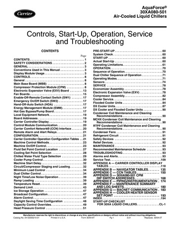
Table 1 — Setup MenuSETUP MENU SSWORDSFUNCTIONThis button specifies the time and date format and the base unit of measure. Time display can be configured as a 12-hourAM/PM setting or as a 24-hour setting. The date can be formatted in one of 3 settings, MM-DD-YYYY (Month-Day-Year),DD-MM-YYYY (Day-Month-Year), or YYYY-MM-DD (Year-Month-Day). Units of measure can be either US (English) orMetric (SI).This button selects the active language and font of the display. Available languages are English and Spanish (Espanol).If a preferred language is not available, additional software for the Main Base Board (MBB) and the Carrier Controllerdisplay are required. Contact your Carrier representative for instructions and software.This button adjusts the LCD contrast. Press and hold the [MOON] button to increase/darken the contrast or the [STAR]button to decrease/lighten the current contrast.NOTE: Touching the screen anywhere for 5 seconds while powering up will prompt the user to restore contrast andcalibration settings to factory defaults.This button specifies whether backlighting should be kept on at all times or turned off during inactive periods.This button is used to adjust the LCD touch screen calibration. Touch the screen in the circular targets located first in theupper left and then in the lower right corner of the screen to adjust.This button is used to configure the limited and full logged-in access system passwords. In order to change passwords,the user must be logged in with full access to view and change the passwords. All passwords must consist of 4 digits,which can be entered using the numeric keypad. Access levels and associated privileges are as follows:Limited Logged-in Access - Provides the user with read/write access to all available tables (except service configurationtables, where the user will not be permitted to modify point data, and Group Display tables, where the user will not bepermitted to add points.) This access level also provides read/write access to all Carrier Controller display setupproperties except Display, CCN, and Password.Full Logged-in Access - Provides user with read/write access to all available tables for the attached device and all CarrierController display properties.DISPLAYIf the user does not log in, read-only access to all tables is allowed. The user will be prompted to log in when attemptingto access password-required functions.This button is used to view the description data and part number from the Ctlr-ID Table and to specify the OperatingMode. The Operating mode can be configured for Equipment mode or Network mode. For Carrier Controller displays thatare standard with the unit, Operating mode should not be changed from Equipment mode. Equipment mode providesaccess only to the chiller’s MBB via the Local Equipment Network (LEN) Bus. For remote access, a remote CarrierController display can be set to Network mode. Network mode provides access to all devices on the CCN (CarrierComfort Network ) bus.CCNNOTE: When changing the operating mode, a power cycle is required in order for the new operating mode to take effect.The user should view and correct the following CCN data: address and baud rate, alarm acknowledger, and broadcastacknowledger designation.This button is used to configure the bus and element numbers and the baud rate of the control on the network.NAVIGATOR DISPLAY MODULEThe Navigator display module provides a mobile user interfaceto the ComfortLink control system. The display has up anddown arrow keys, an ENTER key, and an ESCAPE key.These keys are used to navigate through the different levels ofthe display structure. Press the ESCAPE key until “Select aMenu Item” is displayed. Use the up and down arrow keys tomove through the top 11 mode levels indicated by LEDs on theleft side of the display. See Fig. 7. See Table 2 and Appendix Bfor more details about the display menu structure.ComfortLinkMODEFig. 6 — Setup Menu DisplayRunServiAlarmStatusStatusce TeTempsteraturPressuresSetpointsInputsTo Remove a Point From a Group DisplayFrom the Point Data Dialog box, press the REMOVE button andfollow the prompts. The display will return to the Group Displayscreen from which the point was removed, and the button corresponding to the deleted point will be blank and eAlarmssesESCENTERFig. 7 — Navigator Display Module6
Table 2 — ComfortLink Navigator Display Menu StructureRUNSTATUSAuto Display(VIEW)MachineStarts/Hours(RUN)CompressorRun Hours(HOUR)CompressorStarts(STRT)Fan RunHours(FAN)MODESERVICE TEMPERATURES PRESSURESSETINPUTSOUTPUTS CONFIGURATIONTESTPOINTSManualUnitCircuit ACooling General Circuit ADisplayTest ModeTemperaturesPressuresSetpoints ) (GEN.I)(CIR.A)(DISP)QuickCircuit ACircuit BHeatingCircuit BUnitTest tion(QUIC)(CIR.A)(PRC.B)(HEAT)(CIR.B)(UNIT)Circuit BCircuit CMisc.Cir
vice and Troubleshooting information for the 30XA080-501 air-cooled liquid chillers with electronic controls. The 30XA chillers are equipped with ComfortLink controls and electronic expansion valves. The AquaForce 30XA chillers offer two different user interface devices, the Carrier Controller display and the Navigator display.