Transcription
ARTICLE IN PRESSControl Engineering Practice 14 (2006) d control algorithms embedded in a programmablelogic controllerSamo Gerkšiča, , Gregor Dolanca, Damir Vrančića, Juš Kocijana,b, Stanko Strmčnika,Sašo Blažičc, Igor Škrjancc, Zoran Marinšekd, Miha Božičekd, Anna Stathakie,Robert Kinge, Mincho Hadjiskif, Kosta BoshnakovfaJožef Stefan Institute, Ljubljana, SloveniaNova Gorica Polytechnic, Nova Gorica, SloveniacUniversity of Ljubljana, Faculty of Electrical Engineering, Ljubljana, SloveniadINEA d.o.o., Ljubljana, SloveniaeComputer Technology Institute, Athens, GreecefUniversity of Chemical Technology and Metallurgy Sofia, Sofia, BulgariabReceived 23 April 2004; accepted 15 May 2005Available online 22 July 2005AbstractThis paper presents an innovative self-tuning nonlinear controller ASPECT (advanced control algorithms for programmable logiccontrollers). It is intended for the control of highly nonlinear processes whose properties change radically over its range ofoperation, and includes three advanced control algorithms. It is designed using the concepts of agent-based systems, applied with theaim of automating some of the configuration tasks. The process is represented by a set of low-order local linear models whoseparameters are identified using an online learning procedure. This procedure combines model identification with pre- and postidentification steps to provide reliable operation. The controller monitors and evaluates the control performance of the closed-loopsystem. The controller was implemented on a programmable logic controller (PLC). The performance is illustrated on a field testapplication for control of pressure on a hydraulic valve.r 2005 Elsevier Ltd. All rights reserved.Keywords: Control engineering; Fuzzy modelling; Industrial control; Model-based control; Nonlinear control; Programmable logic controllers; Selftuning regulators1. IntroductionModern control theory offers many control methodsto achieve more efficient control of nonlinear processesthan provided by conventional linear methods, takingadvantage of more accurate process models (Bequette,1991; Henson & Seborg, 1997; Murray-Smith &Johansen, 1997). Surveys (Takatsu, Itoh, & Araki,1998; Seborg, 1999) indicate that while there is a Corresponding author. Tel.: 386 1 477 3994;fax: 386 1 425 7009.E-mail address: samo.gerksic@ijs.si (S. Gerkšič).0967-0661/ - see front matter r 2005 Elsevier Ltd. All rights derable and growing market for advanced controllers, relatively few vendors offer turn-key products.Excellent results of advanced control concepts, basedon fuzzy parameter scheduling (Tan, Hang, & Chai,1997; Babuška, Oosterhoff, Oudshoorn, & Bruijn,2002), multiple-model control (Dougherty & Cooper,2003; Gundala, Hoo, & Piovoso, 2000), and adaptivecontrol (Henson & Seborg, 1994; Hägglund & Åstrom,2000), have been reported in the literature. However,there are several restrictions for applying these methodsin industrial applications, as summarised below:1. Because of the diversity of real-life problems, a singlenonlinear control method has a relatively narrow
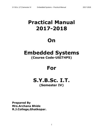
ARTICLE IN PRESS9362.3.4.5.6.S. Gerkšič et al. / Control Engineering Practice 14 (2006) 935–948field of application. Therefore, more flexible methodsor a toolbox of methods are required in industry.New methods are usually not available in a ready-touse industrial form. Custom design requires considerable effort, time and money.The hardware requirements are relatively high, due tothe complexity of implementation and computationaldemands.The complexity of tuning (Babuška et al., 2002) andmaintenance makes the methods unattractive tononspecialised engineers.The reliability of nonlinear modelling is often inquestion.Many nonlinear processes can be controlled using thewell-known and industrially proven PID controller.A considerable direct performance increase (financialgain) is demanded when replacing a conventionalcontrol system with an advanced one. The maintenance costs of an inadequate conventional controlsolution may be less obvious.The aim of this work is to design an advancedcontroller that addresses some of the aforementionedproblems by using the concepts of agent-based systems(ABS) (Wooldridge & Jennings, 1995). The mainpurpose is to simplify controller configuration by partialautomation of the commissioning procedure, which istypically performed by the control engineer. ABS solvedifficult problems by assigning tasks to networkedsoftware agents. The software agents are characterisedby properties such as autonomy (operation withoutdirect intervention of humans), social ability (interactionwith other agents), reactivity (perception and responseto the environment), pro-activeness (goal-directed behaviour, taking the initiative), etc. This work does notaddress issues of ABS theory, but rather the applicationof the basic concepts of ABS to the field of processsystems engineering. In this context, a number of limitshave to be considered. For example: initiative isrestricted, a high degree of reliability and predictabilityis demanded, insight into the problem domain is limitedto the sensor readings, specific hardware platforms areused, etc.The ASPECT controller is an efficient and userfriendly engineering tool for implementation of parameter-scheduling control in the process industry. Thecommissioning of the controller is simplified by automatic experimentation and tuning. A distinguishingfeature of the controller is that the algorithms areadapted for implementation on PLC or open controllerindustrial hardware platforms.The controller parameters are automatically tunedfrom a nonlinear process model. The model is obtainedfrom operating process signals by experimental modelling, using a novel online learning procedure. Thisprocedure is based on model identification using thelocal learning approach (Murray-Smith & Johansen,1997, p. 188). The measurement data are processedbatch-wise. Additional steps are performed before andafter identification in order to improve the reliability ofmodelling, compared to adaptive methods that userecursive identification continuously (Hägglund & Åstrom, 2000).The nonlinear model comprises a set of local loworder linear models, each of which is valid over aspecified operating region. The active local model(s) isselected using a configured scheduling variable. Thecontroller is specifically designed for single-input, singleoutput processes that may include a measured disturbance used for feed-forward. Additionally, theapplication range of the controller depends on theselected control algorithm. A modular structure of thecontroller permits use of a range of control algorithmsthat are most suitable for different processes. Thecontroller monitors the resulting control performanceand reacts to detected irregularities.The controller comprises the run-time module (RTM)and the configuration tool (CT). The RTM runs on aPLC, performing all the main functionality of real-timecontrol, online learning and control performancemonitoring. The CT, used on a personal computer(PC) during the initial configuration phase, simplifies theconfiguration procedure by providing guidance anddefault parameter values.The outline of the paper is as follows: Section 2presents an overview of the RTM structure anddescribes its most important modules; Section 3 givesa brief description of the CT; and finally, Section 4describes the application of the controller to a pilotplant where it is used for control of the pressuredifference on a hydraulic valve in a valve test apparatus.2. Run-Time ModuleThe RTM of the ASPECT controller comprises a setof modules, linked in the form of a multi-agent system.Fig. 1 shows an overview of the RTM and its mainmodules: the signal pre-processing agent (SPA), theonline learning agent (OLA), the model informationagent (MIA), the control algorithm agent (CAA), thecontrol performance monitor (CPM), and the operationsupervisor (OS).2.1. Multi-faceted model (MFM)The ASPECT controller is based on the multi-facetedmodel concept proposed by Stephanopoulus, Henning,and Leone (1990) and incorporates several model formsrequired by the CAA and the OLA. Specifically, theMFM includes a set of local first- and second-orderdiscrete-time linear models with time delay and offset,
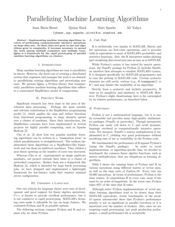
ARTICLE IN PRESSS. Gerkšič et al. / Control Engineering Practice 14 (2006) 935–948937Fig. 1. Run-time module overview.which are specified by a given scheduling variable s(k).The model equation of first order local models isfollowing form:yðk þ 1Þ ¼ a1; j yðkÞ þ b1; j uðk duj Þ þ c1; j vðk dvj Þ þ rj ,yðk þ 1Þ ¼ j¼1(1)while the model equation of second order models isþmXbj ðkÞa1; j yðkÞ mXbj ðkÞa2; j yðk 1Þj¼1bj ðkÞb1; j uðk duj Þj¼1yðk þ 1Þ ¼ a1; j yðkÞ a2; j yðk 1Þ þ b1; j uðk duj Þþ b2; j uðk 1 duj Þ þ c1; j vðk dvj Þþ c2; j vðk 1 dvj Þ þ rj ,mXþbj ðkÞb2;j uðk 1 duj Þj¼1ð2Þwhere k is the discrete time index, j is the number of thelocal model, y(k) is the process output signal, u(k) is theprocess input signal, v(k) is the optional measureddisturbance signal (MD), du is the delay in the modelbranch from u to y, dv is the delay in the model branchfrom v to y, and ai,j, bi,j, ci,j and rj are the parameters ofthe jth local model.The set of local models can be interpreted as aTakagi–Sugeno fuzzy model, which in the caseof a second order model can be expressed in themXþmXbj ðkÞc1; j nðk dnj Þj¼1þmXj¼1bj ðkÞc2; j nðk 1 dnj Þ þmXbj ðkÞrj ,j¼1ð3Þwhere bj( k) is the value of the membership function ofthe jth local model at the current value of the schedulingvariable s(k). Normalised triangular membership functions are used, as illustrated in Fig. 2.
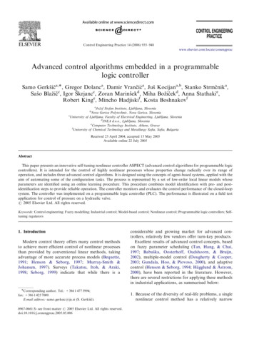
ARTICLE IN PRESS938S. Gerkšič et al. / Control Engineering Practice 14 (2006) 935–948they contain excitation. If the standard deviations of thesignals r(k), y(k), u(k), and v(k) in the active buffer arebelow their thresholds, the execution is cancelled.Fig. 2. Fuzzy membership functions of local models in the MFM.The scheduling variable s(k) is calculated usingcoefficients kr, ky, ku, and kv, using the weighted sumsðkÞ ¼ kr rðkÞ þ ky yðkÞ þ ku uðk 1Þ þ kv vðkÞ.(4)The coefficients are configured by the engineer according to the nature of the process nonlinearity.2.2. Online Learning Agent (OLA)The OLA scans the buffer of recent real-time signals,prepared by the SPA, and estimates the parameters ofthe local models that are excited by the signals. Themost recently derived parameters are submitted to theMIA only when they pass the verification test and areproved to be better than the existing set.The OLA is invoked upon demand from the OS orautonomously, when an interval of the process signalswith sufficient excitation is available for processing. Itprocesses the signals batch-wise and using the locallearning approach. An advantage of the batch-wiseconcept is that the decision on whether to adapt themodel is not performed in real-time but following adelay that allows for inspection of the identificationresult before it is applied. Thus, better means for controlover data selection is provided.A problem of distribution of the computation timerequired for identification appears with batch-wiseprocessing of data (opposed to the online recursiveprocessing that is typically used in adaptive controllers).This problem is resolved using a multi-tasking operationsystem. Since the OLA typically requires considerablymore computation than the real-time control algorithm,it runs in the background as a low-priority task.The following procedure, illustrated in Fig. 3, isexecuted when the OLA is invoked.2.2.1. Copy signal bufferThe buffer of the real-time signals is maintained bythe SPA. When the OLA is invoked, the relevant sectionof the buffer is copied for further processing.2.2.2. Excitation checkA quick excitation check is performed at the start, sothat processing of the signals is performed only when2.2.3. Copy active MFM from MIAThe online learning procedure always compares thenewly identified local models with the previous set ofparameters. Therefore, the active MFM is copied fromthe MIA where it is stored. A default set of modelparameters is used for the local models that have not yetbeen identified (see Section 2.3).2.2.4. Select local modelsA local model is selected if the sum of its membershipfunctions bj(k) over the active buffer normalised bythe active buffer length exceeds a given threshold.Only the selected local models are included in furtherprocessing.2.2.5. IdentificationThe local model parameters are identified using thefuzzy instrumental variables (FIV) identification methoddeveloped by Blažič et al. (2003). It is an extension of thelinear instrumental variables identification procedure(Ljung, 1987) for the specified MFM, based on the locallearning approach (Murray-Smith & Johansen, 1997).The local learning approach is based on the assumptionthat the parameters of all local models will not beestimated in a single regression operation. Compared tothe global approach it is less prone to the problems ofill-conditioning and local minima.This method is well suited to the needs of industrialoperation (intuitiveness, gradual building of the nonlinear model, modest computational demands). Itenables inventory of the local models that are notestimated properly due to insufficient excitation. It isefficient and reliable in early configuration stages, whenall local models have not been estimated yet. On theother hand, the convergence in the vicinity of theoptimum is slow. Therefore, it is likely to yield a worsemodel fit than methods employing nonlinear optimisation. The following briefly describes the procedure.Model identification is performed for each selectedlocal model (denoted by the index j) separately. Theinitial estimated parameter vector h j;MIA is copied fromthe active MFM, and the covariance matrix Pj,MIA isinitialised to 105 I (identity matrix). The FLS (fuzzyleast-squares) estimates, h j;FLS and Pj,FLS, are obtainedusing weighted least-squares identification, with bj(k)used for weighting. The calculation is performedrecursively to avoid matrix inversion. The FIV (fuzzyinstrumental variables) estimates, h j;FIV and Pj,FIV, arecalculated using weighted instrumental variables identification.In order to prevent result degradation by noise, adead zone is used in each step of FIV and FLS recursive
ARTICLE IN PRESSS. Gerkšič et al. / Control Engineering Practice 14 (2006) 935–948939Fig. 3. Online learning procedure.estimation. The vector of parameters and the covariancematrix are updated only if the absolute weighteddifference between the process output and its predictionis above the configured noise threshold.In case of lack of excitation in the branch from u to yor in the model branch from v to y (or when measureddisturbance is not present at all), variants of the methodwith reduced parameter estimate vectors are used.
ARTICLE IN PRESS940S. Gerkšič et al. / Control Engineering Practice 14 (2006) 935–9482.2.6. Verification/validationThis step is performed by comparing the simulationoutput of a selected local model with the actual processoutput in the proximity of the local model position. Thenormalised sum of mean square errors (MSEj) iscalculated. The proximity is defined by the membershipfunctions bj. For each of the selected local models, thisstep is carried out with three sets of model parameters:h j;MIA ; h j;FLS ; and h j;FIV : The set with the lowest MSEj isselected.Then, global verification is performed by comparingthe simulation output of the fuzzy model including theselected set with the actual process output. The normalised sum of mean square errors (MSEG) is calculated. Ifthe global verification result is improved compared tothe initial fuzzy model, the selected set is sent to theMIA as the result of online learning, otherwise theoriginal set h j;MIA remains in use.For each processed local model, the MIA receives theMSEj, which serves as a confidence index, and a flagindicating whether the model is new or not.2.2.7. Model structure estimationTwo model structure estimation units are alsoincluded in the OLA. The dead-time unit (DTU)estimates the process time delay. The membershipfunction unit (MFU) suggests whether a new localmodel should be inserted. It estimates an additionallocal model in the middle of the interval between the twoneighbouring local models that are the most excited. Themodel is submitted to the MIA if the global validationof the resulting fuzzy model is sufficiently improved,compared to the original fuzzy model.2.3. Model Information Agent (MIA)The task of the MIA is to maintain the active MFMand its status information.Its primary activity is processing the online learningresults. When a new local model is received from theOLA, it is accepted if it passes the stability test and itsconfidence index is sufficient. If it is accepted, a ‘‘readyfor tuning’’ flag is set for the CAA. Another flagindicates whether the local model has been tuned sincestart-up or not. If the model confidence index is verylow, the automatic mode may be disabled.The MIA contains a mechanism for inserting additional local models into the MFM. This may occureither by request or automatically, using the MFU ofthe OLA. The MIA may also store the active MFM to alocal database or recall a previously stored one, which isuseful for changing of modes.At initial configuration, the MIA is filled with defaultlocal models based on the initial estimation of theprocess dynamics. They are not exact but may providereliable (although sluggish) control performance, similarto the Safe mode. Using online learning throughexperiments or normal operating records (when theconditions are appropriate for closed-loop identification), an accurate model of the plant is estimatedgradually by receiving identified local models fromthe OLA.2.4. Control Algorithm Agent (CAA)The CAA comprises an industrial nonlinear controlalgorithm and a procedure for automatic tuning of itsparameters from the MFM. Several different CAAs maybe used in the controller and may be interchanged in theinitial configuration phase.The following modes of operation are supported: Manual mode: open-loop operation (actuator constraints are enforced).Safe mode: a fixed PI controller with conservativelytuned parameters.Auto mode (or several auto modes with differenttuning parameters): a nonlinear controller.The CAAs share a common interface of interactionwith the OS and a common modular internal structure,consisting of three layers:1. The control layer offers the functionality of a locallinear controller (or several local linear controllerssimultaneously), including everything required forindustrial control, such as handling of constraintswith anti-windup protection, bump-less mode switching, etc.2. The scheduling layer performs real-time switching orscheduling (blending) of tuned local linear controllers, so that in conjunction with the control layer afixed-parameter nonlinear controller is realised.3. The tuning layer executes the automatic tuningprocedure of the controller parameters from theMFM when the MIA reports that a new local modelis generated if auto-tuning is enabled. The parametersof the control layer and the scheduling layer arereplaced in such a manner that real-time control isnot disturbed.Three CAAs have been developed and each has beenproved effective in specific applications: the Fuzzyparameter-scheduling controller (FPSC), the dead-timecompensation controller (DTCC), and the rule-basedneural controller (RBNC). In this paper, only theconcept of the FPSC is described briefly in the followingsubsection.2.4.1. Fuzzy parameter-scheduling controllerAn overview of the FPSC is shown in Fig. 4.
ARTICLE IN PRESSS. Gerkšič et al. / Control Engineering Practice 14 (2006) 935–948941Fig. 4. FPSC overview.The control layer of the FPSC includes a single PIDcontroller in the form suitable for controller blendingusing velocity-based linearisation. It is equipped withanti-windup protection and bump-less transfer.The scheduling layer of the FPSC performs fuzzyblending of the controller parameters (in the case of Ti,its inverse value) according to the scheduling variables(k) and the membership functions bj(k) of the localmodels. The instrument of velocity-based linearisationenables the dynamics of the blended global controller tobe a linear combination of the local controller dynamicsin the entire operating region, not just around equilibrium operating points. This provides the potential toimprove performance with few local models and moretransparent behaviour in off-equilibrium operatingpoints (Leith & Leithead, 1998; Kocijan, Žunič,Strmčnik, & Vrančić, 2002).The tuning layer of the FPSC is based on themagnitude optimum (MO) criterion implemented usingthe multiple integration (MI) method (Vrančić,Strmčnik, & Juričić, 2001). The MO criterion makesthe magnitude (amplitude) of the system closed-loop setpoint response as flat and close to unity as possible for alarge bandwidth (Whiteley, 1946). This results in arelatively fast and nonoscillatory response of the closedloop system. The expressions for calculating the PIDcontroller parameters using the MO criterion are quitecomplex. However, the MI method significantly simplifies the equations and enables the calculation of the PIDcontroller parameters directly from the process openloop time response.The auto-tuning procedure starts by receiving adiscrete-time local model from the MIA. The model isconverted into a continuous-time local model. Then, theso-called areas are calculated from the model using theMI method. Finally, the PI and PID controllerparameters are calculated from the areas. Thanks tothe transparent concept of the FPSC, an experiencedengineer may choose to configure the control algorithmmanually by specifying the local PID controller positions and parameters, without using the model-basedtuning procedure.2.5. Control performance monitor (CPM)The CPM scans the buffer of recent real-time signalsfor recognisable events. When events are detected, itestimates the features of closed-loop control response
ARTICLE IN PRESS942S. Gerkšič et al. / Control Engineering Practice 14 (2006) 935–948and an overall performance index. Like the OLA, it isinvoked autonomously or upon demand from the OSand runs as a low-priority task. It consists of threemodules: the buffer pre-processor (BP), the situationclassifier (SC), and the performance estimator (PE), asshown in Fig. 5.When the CPM is invoked, the BP copies the relevantsection of the buffer of the real-time signals, which ismaintained by the SPA. It checks if the process is in asteady-state; if so, it terminates processing. Otherwise, itfilters the signals y and v and performs a low-levelanalysis. The SC scans the pre-processed buffer for thelast recognisable event that may be evaluated, or isotherwise important, e.g., a step change of the referencesignal, a step change of the measured disturbance signal,an occurrence of an unmeasured disturbance, or thepresence of oscillation. If an event that may be evaluatedis detected and the conditions for feature estimation arefulfilled (there is no excessive oscillation, the signal-tonoise ratio is sufficient, the process response has settledafter the event and there was a period of steady-statebefore the event), the corresponding buffer interval issent to the PE, otherwise the execution is terminated.The PE may extract the following features of detectedevents: overshoot, settling time, rise time, oscillationdecay rate, and tracking error measure or regulationerror measure. Using a fuzzy evaluation procedure, anoverall performance index (PI) is also calculated fromthe features.The CPM results are sent to the human–machineinterface. If poor performance is detected, the CPMtriggers an automatic switchover to the Safe mode.Other automatic actions include, for example, blockingthe OLA if oscillation is detected. Modifications of theCAA parameters based on CPM results are notgenerally performed because such actions are highlyprocess-specific, but they may be implemented in specificapplications.changes about the operating point of the model in eitheropen or closed loop. In addition, the OS coordinates theOLA, the MIA and the CAA to automatically processthe signals, build the model and tune the localcontrollers. This is the fastest and most reliable way ofcontroller tuning when experimentation with the plant isallowed. Automatic conducting of experiments forclosed-loop performance testing using the CPM is alsosupported.Alternatively, scheduling of experiments may not berequired if experimentation is not allowed. In this case,the controller is initialised in the safe mode, andprocessing of the signals for modelling and tuning istriggered by the OLA autonomously. However, it isrequired that sufficient excitation over the wholeoperating region is available during regular operation.The modelling progress is indicated by the statusflags of the local models in the MIA. The flags showwhich models have been tuned and their confidenceindices.While initiative and suggestions of the agents arehelpful during system configuration, this may not bedesired during regular operation. Therefore, at the endof the commissioning procedure, the system may bereconfigured to simplify the operation as much aspossible.A range of operating regimes can be configured byenabling or disabling the agents and changing theirconfiguration parameters. This results in a flexiblecontrol system that covers the requirements of a widerange of applications and may help diagnose problems.Thus, although designed for control of nonlinearprocesses, the ASPECT controller may also be usedfor adaptive control using a single linear model or as atool for PID controller tuning. Some specific operatingregime options are listed below: 2.6. Operation supervisor (OS) The OS coordinates the control, modelling, andtuning activities of the agents and user interactionthrough the hierarchical set of dialogue windows of thehuman-machine interface (HMI). The OS and the HMIinclude the functionality required for automatic userfriendly experimentation, which is usually required forcontroller tuning.The controller commissioning procedure comprisesthe phases of basic settings, approximate estimation ofthe process dynamics for safe controller tuning, nonlinear modelling and tuning of the scheduling controller,and configuring the regime for regular operation.The OS supports the control engineer by automaticexecution of experiments for identification of localmodels. These experiments consist of a series of step The OLA and/or the CPM may be invoked autonomously (during regular operation) or upon OSdemand (following scheduled experiments), or both.The OLA may estimate the process dead-timecontinuously or not.The OLA may attempt to insert additional localmodels when appropriate, or estimate the localmodels at the fixed pre-selected positions only.Controller retuning may be triggered automaticallyimmediately after each change of the model in MIA(‘‘adaptive’’ operation), or following an engineer’sconfirmation (‘‘self-tuning’’ operation).Online learning may also be used for monitoring ofthe process dynamics without the intention ofcontroller tuning, either by adaptation of the modelor by cross-validation of a fixed model.At start up, the system is initialised from a configuration file, which may put it into any phase of the
ARTICLE IN PRESSS. Gerkšič et al. / Control Engineering Practice 14 (2006) 935–948Fig. 5. CPM overview.943
ARTICLE IN PRESSS. Gerkšič et al. / Control Engineering Practice 14 (2006) 935–948944configuration procedure. Afterwards, the configurationprocedure may be continued or repeated using the HMIdialogue windows.3. Configuration toolThe CT is used on a PC, connected to the PLCrunning the RTM. The CT contains a configuration‘‘wizard’’ that guides the engineer through the typicalscheduling controller commissioning procedure. It isintended for less experienced users. Experienced engineers may find it more efficient to perform configuration only using the RTM, where other sequences of thetasks are possible.The procedure is decomposed into small steps (25dialogue windows). In each step, instructions aredisplayed and default values are suggested by usingrules of thumb, based on the information alreadyavailable. Inconsistency warnings may be displayed.The main phases of the configuration procedure are: Basic settings: selection of the control signals, thesignal limits, the sampling time, the control algorithm, the scheduling variable, the model order.Safe mode configuration: estimation of the processdynamics (experimentation and identification usingthe RTM may be used), self-tuning of the ‘‘safe’’controller parameters (using the RTM), optionalperformance verification.Fuzzy model initialisation: initialisation of the modelpositions, initialisation of the local model parameters,display of the local model parameters and stepresponses.CAA settings: initialisation of the default values,advanced auto-tuning parameters.OLA settings: initialisation of the default values,advanced OLA settings.CPM settings: initialisation of the default values,advanced CPM settings.Experiment settings: initialisation of the defaultvalues, advanced automatic experimentation settings.Local controller tuning: sequence of automatic(open- or closed-loop) experimentation, online learning and tuning using the RTM around each localmodel position.Performance verification: sequence of automaticexperimentation and performance evaluation usingthe RTM around each local model position.The CT relies on the functionality of the RTMwherever possible. However, the PC developmentenvironment is more convenient for graphical userinterface design and enables better visualisation ofresults, compared to typical PLC systems.4. Field testThe ASPECT controller has been tested in severalpilot
identification steps to provide reliable operation. The controller monitors and evaluates the control performance of the closed-loop system. The controller was implemented on a programmable logic controller (PLC). The performance is illustrated on a field test application for control of pressure on a hydraulic valve. r 2005 Elsevier Ltd.