Transcription
Important Notes, ContentsSIMATICS7-200 Programmable ControllerSystem ManualThis manual has the order number:6ES7298-8FA20-8BH0Introducing the S7-200Micro PLCInstalling an S7-200 MicroPLCGetting Started with anS7-200 ProgrammingSystemBasic Concepts forProgramming an S7-200CPU1CPU Memory: Data Typesand Addressing Modes5CPU and Input/OutputConfigurationSetting Up CommunicationsHardware and NetworkCommunications6Conventions for S7-200Instructions8SIMATIC InstructionsIEC 1131-3 InstructionsS7-200 SpecificationsError CodesSpecial Memory (SM) BitsS7-200 TroubleshootingGuide347910ABCExecution Times for STLInstructionsDEFS7-200 Quick ReferenceInformationGS7-200 Order Numbers03/99Release 012Index
Safety GuidelinesThis manual contains notices which you should observe to ensure your own personal safety, as well as toprotect the product and connected equipment. These notices are highlighted in the manual by a warningtriangle and are marked as follows according to the level of danger:!Dangerindicates that death, severe personal injury, or substantial property damage will result if properprecautions are not taken.!Warningindicates that death, severe personal injury, or substantial property damage can result if properprecautions are not taken.!Cautionindicates that minor personal injury or property damage can result if proper precautions are not taken.Qualified PersonnelThe device/system may only be set up and operated in conjunction with this manual. Only qualifiedpersonnel should be allowed to install and work on this equipment. Qualified persons are defined aspersons who are authorized to commission, to ground, and to tag circuits, equipment, and systems inaccordance with established safety practices and standards.Correct UsageNote the following:!WarningThis device and its components may only be used for the applications described in the catalog or thetechnical description, and only in connection with devices or components from other manufacturers whichhave been approved or recommended by Siemens.This product can only function correctly and safely if it is transported, stored, set up, and installedcorrectly, and operated and maintained as recommended.TrademarksSiemensRand SIMATICR are registered trademarks of SIEMENS AG.STEP 7 and S7 are trademarks of SIEMENS AG.MicrosoftR, WindowsR, Windows 95R, Windows 98R, and Windows NTR are registered trademarks ofMicrosoft Corporation.Underwriters LaboratoriesR is a registered trademark of Underwriters Laboratories, Inc.Copyright Siemens AG 1999 All rights reservedDisclaimer of LiabilityThe reproduction, transmission or use of this document or its contents is notpermitted without express written authority. Offenders will be liable fordamages. All rights, including rights created by patent grant or registration ofa utility model or design, are reserved.We have checked the contents of this manual for agreement with thehardware and software described. Since deviations cannot be precludedentirely, we cannot guarantee full agreement. However, the data in thismanual are reviewed regularly and any necessary corrections included insubsequent editions. Suggestions for improvement are welcomed.Siemens AGBereich Automatisierungs- und AntriebstechnikGeschaeftsgebiet Industrie-AutomatisierungssystemePostfach 4848, D-90327 NuernbergIndex-2Siemens AktiengesellschaftE Siemens AG 1999Technicaldatamanualsubject to change.S7-200 Programmable Controller System ManualThishasC79000-G7076-C233the order number:C79000-G7076-C233
Important NotesPurposeThe S7-200 series is a line of micro-programmable logic controllers (Micro PLCs)that can control a variety of automation applications. Compact design, low cost,and a powerful instruction set make the S7-200 controllers a perfect solution forcontrolling small applications. The wide variety of CPU sizes and voltages, and thewindows-based programming tool, give you the flexibility you need to solve yourautomation problems.The S7-200 product line has been redesigned to be smaller, faster, and to haveincreased functionality. The new S7-200 products are intended to replace theprevious products.This manual provides information about installing and programming the S7-200Micro PLCs. The S7-200 Programmable Controller System Manual includes thefollowing topics:Installing and wiringUnderstanding the CPU operations, data types and addressing modes, scancycle, password protection, and network communicationSpecificationsDescriptions of and examples for the SIMATIC and IEC 1131-3 programminginstructionsTypical execution times for SIMATIC STL instructionsAudienceThis manual is designed for engineers, programmers, installers, and electricianswho have a general knowledge of programmable logic controllers.S7-200 Programmable Controller System ManualC79000-G7076-C233-01iii
Important NotesScope of the ManualThe information contained in this manual pertains in particular to the followingproducts:S7-200 CPU models: CPU 221, CPU 222, and CPU 224STEP 7-Micro/WIN 32, version 3.0, a 32-bit programming software package forWindows 95, Windows 98, and the Windows NT environmentAgency ApprovalsThe SIMATIC S7-200 series meets the following regulations:European Community (CE) Low Voltage Directive 73/23/EECEuropean Community (CE) EMC Directive 89/336/EECUnderwriters Laboratories, Inc.: UL 508 Listed (Industrial Control Equipment)Canadian Standards Association: CSA C22.2 Number 142 Certified (ProcessControl Equipment)Factory Mutual Research: FM Class I, Division 2, Groups A, B, C, & DHazardous Locations, T4ARefer to Appendix A for compliance information.Related InformationRefer to the following for more detailed information about selected topics:STEP 7-Micro/WIN 32 CD/disk: provides online help, the STEP 7-Micro/WINGetting Started (a printable online manual).Process Field Bus (PROFIBUS) standard (EN 50170): describes the standardprotocol for the S7-200 DP communication capability.TD 200 Operator Interface User Manual: describes how to install and use theTD 200 with an S7-200 programmable logic controller.ivS7-200 Programmable Controller System ManualC79000-G7076-C233-01
Important NotesHow to Use This ManualIf you are a first-time (novice) user of S7-200 Micro PLCs, you should read theentire S7-200 Programmable Controller System Manual. If you are an experienceduser, refer to the manual table of contents or index to find specific information.The S7-200 Programmable Controller System Manual is organized according tothe following topics:“Introducing the S7-200 Micro PLC” (Chapter 1) provides an overview of someof the features of the equipment.“Installing an S7-200 Micro PLC” (Chapter 2) provides procedures, dimensions,and basic guidelines for installing the S7-200 CPU modules and expansion I/Omodules.“Getting Started with an S7-200 Programming System” (Chapter 3) describeshow to set up an S7-200 programming system.“Basic Concepts for Programming an S7-200 CPU” (Chapter 4), “CPU Memory:Data Types and Addressing Modes” (Chapter 5), and “CPU and Input/OutputControl” (Chapter 6) provide information about how the S7-200 CPU processesdata and executes your program.“Setting Up Communications Hardware and Network Communications”(Chapter 7) provides information about how to install and removecommunications hardware and how to connect the S7-200 CPU to differenttypes of networks.“Conventions for S7-200 Instructions” (Chapter 8) provides an overview of thedifferent programming language concepts and terminology.Descriptions and examples of SIMATIC LAD, FBD, and STL programminginstructions are provided in Chapter 9.Descriptions and examples of IEC 1131-3 LAD and FBD programminginstructions are provided in Chapter 10.Additional information (such as the equipment specifications, error codedescriptions, troubleshooting, and STL instruction execution times) are provided inthe appendices.Additional AssistanceFor assistance in answering technical questions, for training on this product, or forordering, contact your Siemens distributor or sales office.For Internet information about Siemens products and services, technical support,or FAQs (frequently asked questions) and application tips, use the followingInternet ns.com/s7-200S7-200 Programmable Controller System ManualC79000-G7076-C233-01for general Siemens informationfor S7-200 product informationv
Important NotesviS7-200 Programmable Controller System ManualC79000-G7076-C233-01
Contents1234Introducing the S7-200 Micro PLC . . . . . . . . . . . . . . . . . . . . . . . . . . . . . . . . . . . . . . .1-11.1Comparing the Features of the S7-200 Micro PLCs . . . . . . . . . . . . . . . . . .1-21.2Major Components of the S7-200 Micro PLC . . . . . . . . . . . . . . . . . . . . . . . .1-4Installing an S7-200 PLC . . . . . . . . . . . . . . . . . . . . . . . . . . . . . . . . . . . . . . . . . . . . . . . .2-12.1Panel Layout Considerations . . . . . . . . . . . . . . . . . . . . . . . . . . . . . . . . . . . . . .2-22.2Installing and Removing an S7-200 Micro PLC or Expansion Module . . .2-62.3Installing the Field Wiring . . . . . . . . . . . . . . . . . . . . . . . . . . . . . . . . . . . . . . . . .2-92.4Using Suppression Circuits . . . . . . . . . . . . . . . . . . . . . . . . . . . . . . . . . . . . . . .2-162.5Power Considerations . . . . . . . . . . . . . . . . . . . . . . . . . . . . . . . . . . . . . . . . . . . .2-18Getting Started with an S7-200 Programming System . . . . . . . . . . . . . . . . . . . . .3-13.1Overview . . . . . . . . . . . . . . . . . . . . . . . . . . . . . . . . . . . . . . . . . . . . . . . . . . . . . . .3-23.2Quick Start for STEP 7-Micro/WIN 32 . . . . . . . . . . . . . . . . . . . . . . . . . . . . . .3-33.3How Do I Set Up Communications Using the PC/PPI Cable? . . . . . . . . . .3-53.4How Do I Go Online With the S7-200 CPU? . . . . . . . . . . . . . . . . . . . . . . . . .3-93.5How Do I Change the Communications Parameters for My PLC? . . . . . .3-10Basic Concepts for Programming an S7-200 CPU . . . . . . . . . . . . . . . . . . . . . . . . .4-14.1Guidelines for Designing a Micro PLC System . . . . . . . . . . . . . . . . . . . . . . .4-24.2Concepts of an S7-200 Program . . . . . . . . . . . . . . . . . . . . . . . . . . . . . . . . . .4-54.3Concepts of the S7-200 Programming Languages and Editors . . . . . . . . .4-64.4Understanding the Differences between SIMATIC andIEC 1131-3 Instructions . . . . . . . . . . . . . . . . . . . . . . . . . . . . . . . . . . . . . . . . . .4-104.5Basic Elements for Constructing a Program . . . . . . . . . . . . . . . . . . . . . . . . .4-184.6Understanding the Scan Cycle of the CPU . . . . . . . . . . . . . . . . . . . . . . . . . .4-224.7Selecting the Mode of Operation for the CPU . . . . . . . . . . . . . . . . . . . . . . .4-254.8Creating a Password for the CPU . . . . . . . . . . . . . . . . . . . . . . . . . . . . . . . . . .4-274.9Debugging and Monitoring Your Program . . . . . . . . . . . . . . . . . . . . . . . . . . .4-304.10Error Handling for the S7-200 CPU . . . . . . . . . . . . . . . . . . . . . . . . . . . . . . . .4-36S7-200 Programmable Controller System ManualC79000-G7076-C233-01vii
Contents5678viiiCPU Memory: Data Types and Addressing Modes . . . . . . . . . . . . . . . . . . . . . . . .5-15.1Direct Addressing of the CPU Memory Areas . . . . . . . . . . . . . . . . . . . . . . .5-25.2SIMATIC Indirect Addressing of the CPU Memory Areas . . . . . . . . . . . . . .5-135.3Memory Retention for the S7-200 CPU . . . . . . . . . . . . . . . . . . . . . . . . . . . . .5-155.4Using Your Program to Store Data Permanently . . . . . . . . . . . . . . . . . . . . .5-205.5Using a Memory Cartridge to Store Your Program . . . . . . . . . . . . . . . . . . .5-22CPU and Input/Output Configuration . . . . . . . . . . . . . . . . . . . . . . . . . . . . . . . . . . . . .6-16.1Local I/O and Expansion I/O . . . . . . . . . . . . . . . . . . . . . . . . . . . . . . . . . . . . . .6-26.2Using the Selectable Input Filter to Provide Noise Rejection . . . . . . . . . . .6-46.3Pulse Catch . . . . . . . . . . . . . . . . . . . . . . . . . . . . . . . . . . . . . . . . . . . . . . . . . . . .6-56.4Using the Output Table to Configure the States of the Outputs . . . . . . . . .6-86.5Analog Input Filter . . . . . . . . . . . . . . . . . . . . . . . . . . . . . . . . . . . . . . . . . . . . . . .6-96.6High-Speed I/O . . . . . . . . . . . . . . . . . . . . . . . . . . . . . . . . . . . . . . . . . . . . . . . . .6-106.7Analog Adjustments . . . . . . . . . . . . . . . . . . . . . . . . . . . . . . . . . . . . . . . . . . . . .6-13Setting Up Communications Hardware and Network Communications . . . . . .7-17.1What Are My Communication Choices? . . . . . . . . . . . . . . . . . . . . . . . . . . . .7-27.2Installing and Removing Communication Interfaces . . . . . . . . . . . . . . . . . .7-77.3Selecting and Changing Parameters . . . . . . . . . . . . . . . . . . . . . . . . . . . . . . .7-97.4Communicating With Modems . . . . . . . . . . . . . . . . . . . . . . . . . . . . . . . . . . . .7-167.5Network Overview . . . . . . . . . . . . . . . . . . . . . . . . . . . . . . . . . . . . . . . . . . . . . . .7-277.6Network Components . . . . . . . . . . . . . . . . . . . . . . . . . . . . . . . . . . . . . . . . . . . .7-317.7Using the PC/PPI Cable with Other Devices and Freeport . . . . . . . . . . . .7-357.8Network Performance . . . . . . . . . . . . . . . . . . . . . . . . . . . . . . . . . . . . . . . . . . . .7-41Conventions for S7-200 Instructions . . . . . . . . . . . . . . . . . . . . . . . . . . . . . . . . . . . . .8-18.1Concepts and Conventions For STEP 7-Micro/WIN 32 Programming . . .8-28.2Valid Ranges for the S7-200 CPUs . . . . . . . . . . . . . . . . . . . . . . . . . . . . . . . .8-7S7-200 Programmable Controller System ManualC79000-G7076-C233-01
Contents910SIMATIC Instructions . . . . . . . . . . . . . . . . . . . . . . . . . . . . . . . . . . . . . . . . . . . . . . . . . . .9-19.1SIMATIC Bit Logic Instructions . . . . . . . . . . . . . . . . . . . . . . . . . . . . . . . . . . . .9-29.2SIMATIC Compare Instructions . . . . . . . . . . . . . . . . . . . . . . . . . . . . . . . . . . .9-109.3SIMATIC Timer Instructions . . . . . . . . . . . . . . . . . . . . . . . . . . . . . . . . . . . . . . .9-159.4SIMATIC Counter Instructions . . . . . . . . . . . . . . . . . . . . . . . . . . . . . . . . . . . . .9-239.5SIMATIC High-Speed Counter Instructions . . . . . . . . . . . . . . . . . . . . . . . . . .9-279.6SIMATIC Pulse Output Instructions . . . . . . . . . . . . . . . . . . . . . . . . . . . . . . . .9-499.7SIMATIC Clock Instructions . . . . . . . . . . . . . . . . . . . . . . . . . . . . . . . . . . . . . . .9-709.8SIMATIC Integer Math Instructions . . . . . . . . . . . . . . . . . . . . . . . . . . . . . . . .9-729.9SIMATIC Real Math Instructions . . . . . . . . . . . . . . . . . . . . . . . . . . . . . . . . . . .9-819.10SIMATIC Move Instructions . . . . . . . . . . . . . . . . . . . . . . . . . . . . . . . . . . . . . . .9-999.11SIMATIC Table Instructions . . . . . . . . . . . . . . . . . . . . . . . . . . . . . . . . . . . . . . . 9-1049.12SIMATIC Logical Operations Instructions . . . . . . . . . . . . . . . . . . . . . . . . . . . 9-1109.13SIMATIC Shift and Rotate Instructions . . . . . . . . . . . . . . . . . . . . . . . . . . . . . 9-1169.14SIMATIC Conversion Instructions . . . . . . . . . . . . . . . . . . . . . . . . . . . . . . . . . . 9-1269.15SIMATIC Program Control Instructions . . . . . . . . . . . . . . . . . . . . . . . . . . . . . 9-1419.16SIMATIC Interrupt and Communications Instructions . . . . . . . . . . . . . . . . . 9-1659.17SIMATIC Logic Stack Instructions . . . . . . . . . . . . . . . . . . . . . . . . . . . . . . . . . 9-192IEC 1131-3 Instructions . . . . . . . . . . . . . . . . . . . . . . . . . . . . . . . . . . . . . . . . . . . . . . . . .10-110.1IEC Bit Logic . . . . . . . . . . . . . . . . . . . . . . . . . . . . . . . . . . . . . . . . . . . . . . . . . . .10-210.2IEC Compare Instructions . . . . . . . . . . . . . . . . . . . . . . . . . . . . . . . . . . . . . . . .10-710.3IEC Timer Instructions . . . . . . . . . . . . . . . . . . . . . . . . . . . . . . . . . . . . . . . . . . . 10-1110.4IEC Counter Instructions . . . . . . . . . . . . . . . . . . . . . . . . . . . . . . . . . . . . . . . . . 10-1510.5IEC Math Instructions . . . . . . . . . . . . . . . . . . . . . . . . . . . . . . . . . . . . . . . . . . . . 10-1910.6IEC Move Instructions . . . . . . . . . . . . . . . . . . . . . . . . . . . . . . . . . . . . . . . . . . . 10-2410.7IEC Logic Instructions . . . . . . . . . . . . . . . . . . . . . . . . . . . . . . . . . . . . . . . . . . . . 10-2610.8IEC Shift and Rotate Instructions . . . . . . . . . . . . . . . . . . . . . . . . . . . . . . . . . . 10-2910.9IEC Conversion Instructions . . . . . . . . . . . . . . . . . . . . . . . . . . . . . . . . . . . . . . 10-32S7-200 Programmable Controller System ManualC79000-G7076-C233-01ix
ContentsAS7-200 Specifications . . . . . . . . . . . . . . . . . . . . . . . . . . . . . . . . . . . . . . . . . . . . . . . . . . .A-1A.1General Technical Specifications . . . . . . . . . . . . . . . . . . . . . . . . . . . . . . . . . .A-2A.2Specifications for the CPU 221 . . . . . . . . . . . . . . . . . . . . . . . . . . . . . . . . . . . .A-6A.3Specifications for the CPU 222 . . . . . . . . . . . . . . . . . . . . . . . . . . . . . . . . . . . .A-11A.4Specifications for the CPU 224 . . . . . . . . . . . . . . . . . . . . . . . . . . . . . . . . . . . .A-16A.5Specifications for the EM221 Digital Input Module . . . . . . . . . . . . . . . . . . . .A-21A.6Specifications for the EM222 Digital Output Modules . . . . . . . . . . . . . . . . .A-23A.7Specifications for the EM223 Digital Combination Modules,8 Inputs/8 Outputs . . . . . . . . . . . . . . . . . . . . . . . . . . . . . . . . . . . . . . . . . . . . . . .A-25A.8Optional Cartridges . . . . . . . . . . . . . . . . . . . . . . . . . . . . . . . . . . . . . . . . . . . . .A-28A.9I/O Expansion Cable . . . . . . . . . . . . . . . . . . . . . . . . . . . . . . . . . . . . . . . . . . . . .A-29A.10PC/PPI Cable . . . . . . . . . . . . . . . . . . . . . . . . . . . . . . . . . . . . . . . . . . . . . . . . . . .A-30Error Codes . . . . . . . . . . . . . . . . . . . . . . . . . . . . . . . . . . . . . . . . . . . . . . . . . . . . . . . . . . . .B-1B.1Fatal Error Codes and Messages . . . . . . . . . . . . . . . . . . . . . . . . . . . . . . . . . .B-2B.2Run-Time Programming Problems . . . . . . . . . . . . . . . . . . . . . . . . . . . . . . . . .B-3B.3Compile Rule Violations . . . . . . . . . . . . . . . . . . . . . . . . . . . . . . . . . . . . . . . . . .B-4CSpecial Memory (SM) Bits . . . . . . . . . . . . . . . . . . . . . . . . . . . . . . . . . . . . . . . . . . . . . . .C-1DS7-200 Troubleshooting Guide . . . . . . . . . . . . . . . . . . . . . . . . . . . . . . . . . . . . . . . . . .D-1ES7-200 Order Numbers . . . . . . . . . . . . . . . . . . . . . . . . . . . . . . . . . . . . . . . . . . . . . . . . . .E-1FExecution Times for STL Instructions . . . . . . . . . . . . . . . . . . . . . . . . . . . . . . . . . . . .F-1GS7-200 Quick Reference Information . . . . . . . . . . . . . . . . . . . . . . . . . . . . . . . . . . . . .G-1BIndex . . . . . . . . . . . . . . . . . . . . . . . . . . . . . . . . . . . . . . . . . . . . . . . . . . . . . . . . . . . . . . . . Index-1xS7-200 Programmable Controller System ManualC79000-G7076-C233-01
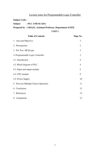
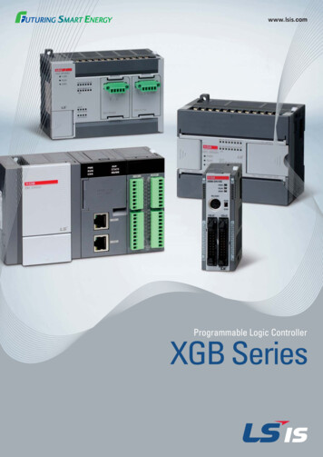
Introducing the S7-200 Micro PLC1The S7-200 series is a line of micro-programmable logic controllers (Micro PLCs)that can control a variety of automation applications. Figure 1-1 shows an S7-200Micro PLC. The compact design, expandability, low cost, and powerful instructionset of the S7-200 Micro PLC make a perfect solution for controlling smallapplications. In addition, the wide variety of CPU sizes and voltages provides youwith the flexibility you need to solve your automation problems.Figure 1-1S7-200 Micro PLCChapter OverviewSectionDescriptionPage1.1Comparing the Features of the S7-200 Micro PLCs1-21.2Major Components of the S7-200 Micro PLC1-4S7-200 Programmable Controller System ManualC79000-G7076-C233-011-1
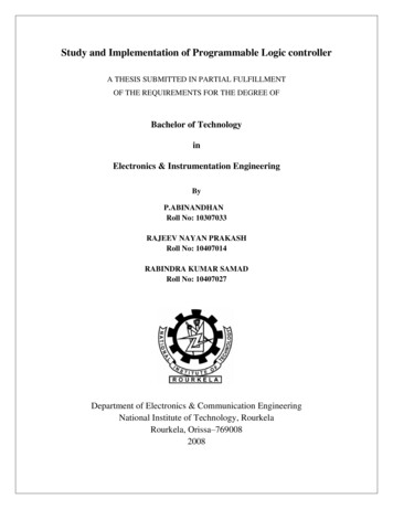
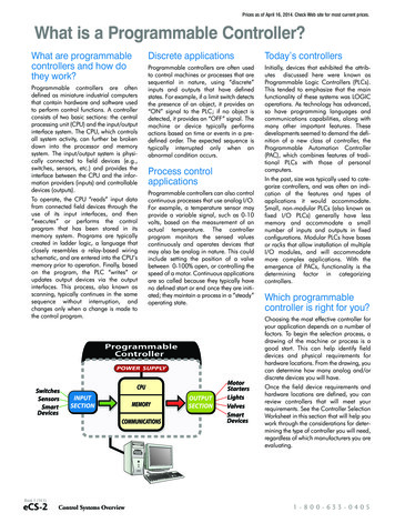
Introducing the S7-200 Micro PLC1.1Comparing the Features of the S7-200 Micro PLCsEquipment RequirementsFigure 1-2 shows the basic S7-200 Micro PLC system, which includes an S7-200CPU, a personal computer, STEP 7-Micro/WIN 32, version 3.0 programmingsoftware, and a communications cable.In order to use a personal computer (PC), you must have one of the following:A PC/PPI cableA communications processor (CP) and multipoint interface (MPI) cableA multipoint interface (MPI) card. A communications cable is provided with theMPI card.ComputerS7-200 CPUSTEP 7-Micro/WIN 32PC/PPI CableFigure 1-2Components of an S7-200 Micro PLC SystemCapabilities of the S7-200 CPUsThe S7-200 family includes a wide variety of CPUs. This variety provides a rangeof features to aid in designing a cost-effective automation solution. Table 1-1provides a summary of the major features of the S7-200 CPUs.1-2S7-200 Programmable Controller System ManualC79000-G7076-C233-01
Introducing the S7-200 Micro PLCTable 1-1Summary of the S7-200 CPUsCPU 221FeatureCPU 222CPU �ÁÁÁÁÁÁÁÁPhysical Size of Unit90 mm x 80 mm x62 mm90 mm x 80 mm x62 mm120.5 mm x 80 mmx 62 mmProgram2048 words2048 words4096 wordsUser data1024 words1024 words2560 wordsMemory typeEEPROMEEPROMEEPROMMemory cartridgeEEPROMEEPROMEEPROMData backup (super capacitor)50 hours typical50 hours typical190 hours typicalLocal I/O6 In/4 Out8 In/6 Out14 In/10 OutNumber of expansion modulesnone2 modules7 modulesDigital I/O image size256 (128 In/128 Out)256 (128 In/128 Out)256 (128 In/128 Out)Digital I/O physical size1062128Analog I/O image sizenone16 In/16 Out16 In/16 OutAnalog I/O physical sizenone12 In/10 Out12 In/10 OutBoolean execution speed0.37 µs/instruction0.37 µs/instruction0.37 µs/instructionInternal 6Sequential control relays256256256For/Next loopsYesYesYesInteger math ( - * /)YesYesYesReal math ( - * /)YesYesYesBuilt-in high-speed counter4 (20 KHz)4 (20 KHz)6 (20 KHz)Analog adjustments112Pulse outputs2 (20 KHz, DC only)2 (20 KHz, DC only)2 (20 KHz, DC only)Communication interrupts1 transmit/2 receive1 transmit/2 receive1 transmit/2 receiveTimed interrupts2 (1 ms to 255 ms)2 (1 ms to 255 ms)2 (1 ms to 255 ms)Hardware input interrupts444Real-time clockYes (cartridge)Yes (cartridge)Yes (built-in)Password protectionYesYesYesNumber of communication ports:1 (RS-485)1 (RS-485)1 (RS-485)Protocols supported Port 0:PPI, MPI slave,FreeportPPI, MPI slave,FreeportPPI, MPI slave,FreeportPROFIBUS yLocal I/OTotal �ÁÁÁÁÁInstructionsEnhanced FeaturesCommunicationsS7-200 Programmable Controller System ManualC79000-G7076-C233-011-3
Introducing the S7-200 Micro PLC1.2Major Components of the S7-200 Micro PLCAn S7-200 Micro PLC consists of an S7-200 CPU alone or with a variety ofoptional expansion modules.S7-200 CPUThe S7-200 CPU combines a central processing unit (CPU), power supply, anddiscrete I/O points into a compact, stand-alone device.The CPU executes the program and stores the data for controlling theautomation task or process.Additional I/O points can be added to the CPU with expansion modules up tothe physical size limits listed in Table 1-1.The power supply provides electrical power for the base unit and for anyexpansion module that is connected.The inputs and outputs are the system control points: the inputs monitor thesignals from the field devices (such as sensors and switches), and the outputscontrol pumps, motors, or other devices in your process.The communications port allows you to connect the CPU to a programmingdevice or to other devices.Status lights provide visual information about the CPU mode (RUN or STOP),the current state of the local I/O, and whether a system fault has beendetected.Some CPUs provide a real-time clock as a built-in feature, while other CPUsrequire the real-time clock cartridge.A plug-in serial EEPROM cartridge provides a means to store CPU programsand transfer programs from one CPU to another.A plug-in battery cartridge provides extended retention of data memory in RAM.1-4S7-200 Programmable Controller System ManualC79000-G7076-C233-01
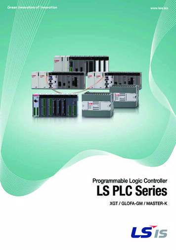
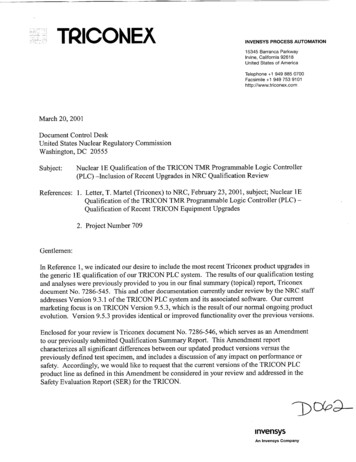
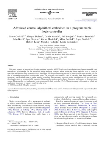
Introducing the S7-200 Micro PLCFigure 1-3 shows the S7-200 CPU.Status LEDsTop terminal doorPower terminalOutput terminalCartridgeFront access doorRUN STOP switchPotentiometerExpansion I/O connectionCommunicationPortBottom terminal doorInput terminalSensor powerFigure 1-3S7-200 CPUExpansion ModulesThe S7-200 CPU provides a certain number of local I/O. Adding an expansionmodule provides additional input or output points (see Figure 1-4).Figure 1-4CPU with an Expansion ModuleS7-200 Programmable Controller System ManualC79000-G7076-C233-011-5
Introducing the S7-200 Micro PLC1-6S7-200 Programmable Controller System ManualC79000-G7076-C233-01
2Installing an S7-200 PLCThe installation of the S7-200 equipment is designed to be easy. You can use themounting holes to attach the modules to a panel, or you can use the built-in clips tomount the modules onto a standard (DIN) rail. The small size of the S7-200 allowsyou to make efficient use of space.This chapter provides guidelines for installing and wiring your S7-200 system.Chapter OverviewSectionDescriptionPage2.1Panel Layout Considerations2-22.2Installing and Removing an S7-200 Micro PLC or ExpansionModule2-62.3Installing the Field Wiring2-92.4Using Suppression Circuits2-162.5Power Considerations2-18S7-200 Programmable Controller System ManualC79000-G7076-C233-012-1
Installing an S7-200 PLC2.1Panel Layout ConsiderationsInstallation ConfigurationYou can install an S7-200 either on a panel or on a standard rail. You can mountthe S7-200 either horizontally or vertically. You can connect the S7-200 toexpansion modules by one of these methods:A flexible ribbon cable with mating connector is built into the I/O module foreasy connection to the PLC or another expansion module.An I/O expansion cable is also available to add flexibility to your mountingconfiguration.Figure 2-1 shows a typical configuration for these types of installations.Panel mountingS7-200I/OStandard rail mountingI/OS7-200I/OI/OFigure 2-12-2I/OI/OMounting ConfigurationsS7-200 Programmable Controller System ManualC79000-G7076-C233-01
Installing an S7-200 PLCClearance Requirements for Installing an S7-200 PLCUse the following guidelines as you plan your installation:The S7-200 CPU and expansion modules are designed for natural convectioncooling. You must provide a clearance of at least 25 mm (1 in.), both above andbelow the units, for proper cooling. See Figure 2-2. Continuous operation of allelectronic products at maximum ambient temperature and load reduces theirlife.For vertical mounting, the maximum ambient temperature is reduced by 10 C.The CPU should be mounted below any expansion modules. If you aremounting on a vertical DIN rail, you should use the DIN rail stop.Allow 75 mm (3 in.) for mounting depth. See Figure 2-2.Be sure to allow enough space in your mounting design to accommodate theI/O wiring and communication cable connections.25 mm(1 ÂÂÂÂÂÂÂÂÂÂÂÂClearance for cooling25 mm(1 in.)S7-200Front ViewFigure 2-2I/OFront of theenclosureS7-200Mountingsurface75 mm(3 in.)Side ViewHorizontal and Vertical Clearance Requirements for Installing an S7-200 PLCS7-200 Programmable Controller System ManualC79000-G7076-C233-012-3
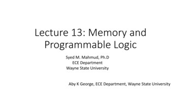
Installing an S7-200 PLCStandard Rail RequirementsThe S7-200 CPU and expansion modules can be installed on a standard (DIN) rail(DIN EN 50 022). Figure 2-3 shows the dimensions for this rail.1.0 mm(0.04 in.)35 mm(1.38 in.)7.5 mm(0.30 in.)Figure 2-3Standard Rail DimensionsPanel-Mounting DimensionsS7-200 CPUs and expansion modules include mounting holes to facilitateinstallation on panels. Figure 2-4 through Figure 2-6 provide the mountingdimensions for the different S7-200 CPUs and expansion modules.90 mm(3.54 in.)4 mm(0.16 in.)82 mm(3.23 in.)4 mm(0.16 in.)88 mm(3.46 in.)96 mm(3.78 in.)80 mm(3.15 in.)CPU 221CPU 2224 mm(0.16 in.)Figure 2-42-4ÁÁMounting holes(M4 or No. 8)Mounting Dimensions for CPU 221 and CPU 222S7-200 Programmable Controller System ManualC79000-G7076-C233-01
Installing an S7-200 PLC4 mm(0.16 in.)120.5 mm(4.74 in.)4 mm(0.16 in.)112.5 mm(4.43 in.)88 mm(3.46 in.)96 mm(3.78 in.)CPU 22480 mm(3.15 in.)ÁÁ4 mm(0.16 in.)Figure 2-5Mounting Dimensions for a CPU 224Mounting holes(M4 or No. 8)ExistingCPU orExpansionModule4 mm(0.16 4 mm(0.16 in.)96 mm(3.78 in.)16-PointExpansionModule88 mm(3.46 in.)80 mm(3.15 in.)ÁÁÁÁ38 mm(1.50 in.)9.5 mm*(0.37 in.)63.2 mm(2.49 in.)46 mm(1.81 in.)71.2 mm(2.80 in.)9.5 mm*(0.37 in.)
S7-200 Programmable Controller System Manual C79000-G7076-C233-01 Important Notes Purpose The S7-200 series is a line of micro-programmable logic controllers (Micro PLCs) that can control a variety of automation applications. Compact design, low cost, and a powerful instruction set make the S7-200 controllers a perfect solution for