Transcription
International Journal of Automotive and Mechanical Engineering (IJAME)ISSN: 2229-8649 (Print); ISSN: 2180-1606 (Online); Volume 9, pp. 1550-1563, January-June 2014 Universiti Malaysia PahangDOI: ND VISCOUS EFFECT ON 3D FLOW STRUCTURE OF A COMPOUNDWING-IN-GROUND EFFECTS. Jamei, A. Maimun, N. Azwadi, M. M. Tofa, S. Mansor and A. Priyanto1Faculty of Mechanical Engineering, Universiti Teknologi Malaysia81310, UTM Skudai, Johor, Malaysia*Email: jsaeed2@live.utm.myPhone: 607-553-5957; Fax: 607-553-5708ABSTRACTThe wing-in-ground-effect craft is a new means for traveling on rivers, lakes, and at seabetween islands. In this study, the effect of boundary layers due to the ground viscouseffect on the aerodynamic coefficients of the compound wing of a WIG craft wasnumerically investigated. The compound wing is divided into three parts, with onerectangular wing in the middle and two reverse taper wings with an anhedral angle atthe sides. A realizable k-ε turbulent model was used for modeling the flow around thewing area. The computational results of the compound wing for fixed ground werecompared with the experimental data. The aerodynamic characteristics of the compoundwing were examined via both fixed and moving ground for removing the boundarylayers effect of the ground. Accordingly, the numerical result indicated that the lift anddrag coefficients and lift to drag ratio are affected by the ground boundary layers whilethe moment coefficient and center of pressure of the compound wing showed littlevariation with respect to ground boundary conditions.Keywords: Aerodynamics; boundary layer; compound wing; CFD simulation; WIGcraft.INTRODUCTIONFast-marine transportation around and among islands and coastal areas has developedfor many services such as passenger travel, military use and rescue. Wing-in-groundeffect (Ludwig, McGregor, Blowes, Benner, & Mountjoy, 2002) vehicles are highspeed craft which are a promising option for both work and travel because of theireconomic benefits (Yun, Bliault, & Doo, 2009). A WIG craft has two advantagescompared with aircraft. First is the higher ram pressure because of trapping of the airflow around the stagnation point on the lower surface of the wing in proximity to theground. Next, the induced drag is weaker because the wing is near the ground, so the tipvortex is trapped by the ground and reduces the strength of vortices (Abramowski,2007). The effect of ground boundary layers on the performance of the wing-in-groundeffect is a challenge for researchers (Marqués-Bruna, 2011; Saad & Bari, 2013;Tahseen, Ishak, & Rahman, 2013; Yang, Yang, & Jia, 2010; Ying, Yang, & Yang,2010a, 2010b). Yang, Z. G. et al. (2010) showed an effective height decrease because ofthe rise of ground by using a displacement thickness which caused an over-estimation ofthe ground effect. A separation bubble was created on the ground when the ground wasconsidered as a fixed boundary. The separation bubble could rise with reduced groundclearance and a higher angle of attack. As a result, the passageway of the air flow wasreduced and then the ram effect decreased and lift would be underestimated. In addition,1550
Jamei et al. /International Journal of Automotive and Mechanical Engineering 9 (2014) 1550-1563the separation bubble caused the stagnation point to move towards the leading edge andthen the air flow on the upper surface of the wing had higher energy with lower adversepressure gradients, where there was a delay on the separation at the trailing edge andstall angle as well (Yang, Lin, & Yang, 2010). Yang, W. et al. (2010) illustrated thatthe separation bubble is developed more by the ground level than by the angle of attack.Ying et al. (2010a) demonstrated that the separation bubble was removed at a groundclearance greater than 0.2, and that therefore the aerodynamic behavior of the air flowon fixed ground was similar to moving ground.Yang and Yang (2009) tried to identify numerically the ground viscous effect onthe wing-in-ground effect. They showed a negative lift coefficient and a rapid increaseof drag coefficient with a small angle of attack (AOA 4 ) in low ground clearance(h/c 0.1). At an angle of attack of 4 and with different ground clearances, theyreported a higher lift and lower drag for fixed ground compared to moving ground; butthis difference reduced at higher ground clearance. The interaction of the boundarylayer of fixed ground and the model when tested in a wind tunnel has a greater influenceon the aerodynamic forces than in real flight (Borello et al., 1999). Therefore, the effectof the ground boundary layer in some testing should be removed, for example, invehicle testing. The moving belt is one method to reduce this effect (Barber, Leonardi,& Archer, 2002), although this method is not always feasible. Knowles, Donoghue, andFinnis (1994) believed that the boundary layer reduces the effective ground clearance ofthe wing, which improves the venture effect between the wing and ground. Therefore,flow velocities are accelerated, which results in lower pressure and higher downforce.Marshall, Newman, and Williams (2010) demonstrated the influence of the boundarylayer on an inverted wing ground effect when there is no moving ground. Theyobserved that a larger boundary layer induced stronger pressure and consequentlysmaller flow velocities. A larger downforce was recorded for a smaller boundary layerheight because of the lower pressure suction surface. Jamei, Maimun, Mansor, Azwadi,and Priyanto (2012) numerically investigated the aerodynamic characteristics of acompound wing-in-ground effect. The compound wing is divided into two parts: themiddle part as the rectangular wing and the side parts that are reverse taper wings withan anhedral angle. They showed that compound wings can create a greater reduction ofdownwash velocity and modify the pressure distribution on the lower side, which leadsto a higher augmentation in the lift force. Also, the smaller distance between the wingtip of compound wings and the ground causes a reduction of drag because of the weakertip vortex. In addition, the performance, fuel consumption and environmental impact ofcompound wings have been investigated by Jamei, Maimun, Mansor, Azwadi, andPriyanto (2011). The lower drag of compound wings allows a considerable reduction infuel consumption, which could be an economic advantage. Accordingly, the CO2emission related to compound wings is much less than that of a rectangular wing.According to the previous research, the effect of ground boundary layers on theaerodynamics of the wing is still a major objective for researchers. In this paper, theeffect of ground viscous boundary layers on the aerodynamics coefficient of acompound wing-in-ground effect (Jamei et al., 2012) was numerically investigated.Two ground boundaries were used in the simulations, fixed ground and moving ground.In this research, the lift and drag coefficient, lift to drag ratio, moment coefficient andcenter of pressure of the present compound wing were measured, as these could beaffected by the ground viscous effect. The pressure and velocity distributions as well asthe aerodynamic coefficients of the compound wing were analyzed for each groundboundary.1551
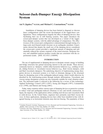
Ground viscous effect on 3D flow structure of a compound wing-in-ground effectCFD NUMERICAL STUDYThe numerical study was performed on a compound wing with NACA6409 airfoilsection. The principal dimensions of the compound wing (Figure 1) are shown in Table1 (Jamei et al., 2012). These simulations were prepared with respect to different anglesof attack and ground clearances (h/c), aspect ratio 1.25, and velocity of airflow 25.5m/s, in addition to which two ground boundary conditions were considered, fixed andmoving. Ground level (h) is defined by the distance between the center of the trailingedge of the wing and the ground surface. CFD methods are based on the solution ofNavier–Stokes equations by using the finite volume method (FVM). Many flows ofengineering significance are turbulent, especially in aerospace applications. The flowfield around the compound wing was assumed to be steady-state and incompressible bymeans of a realizable k-ε turbulent model. Fluent software was employed for the CFDsimulations. Shih, Liou, Shabbir, Yang, and Zhu (1995) recommended a realizable k-εturbulent model which used a new turbulent viscosity formula and a new dissipationrate equation (ε) according to the dynamic equation of the mean-square vorticesfluctuation. The transport equations for the turbulent kinetic energy (k) and turbulentdissipation energy (ε) are expressed as follows: ( k ) ( ku j ) t x j x j t k k Gk Gb YM Sk x j (1)and t ( ) ( u j ) t x j x j C1 k 2 CS C 12k x j (2)C3 Gb S kC1 max 0.43,, , S 2S ij S ij 5 (3)where Sk and Sε are user-defined source terms, C1ε, C2, C3ε, σk and σε are the adaptableconstants.The aerodynamic coefficients and center of pressure in this numerical studywere determined as follows:CL CMDLMX CP 0.25 CD CM 222Ccos CD sin .0.5 U Ac and0.5 U A ,0.5 U A ,LIn this study, the standard wall functions (Launder & Spalding, 1974) wereemployed in the numerical simulation. The wall functions have certain advantages, suchas being less time-consuming, reducing the number of meshes near the walls such as thewing, being cost-effective and having acceptable accuracy. Based on the currentsimulation, the mesh number was around 4,500,000, which yielded acceptableconvergence.1552
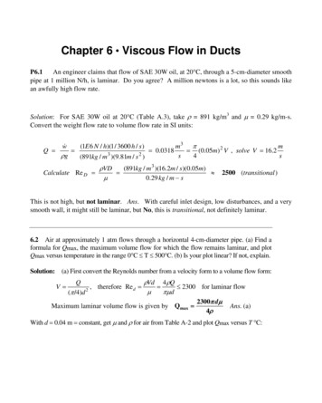
Jamei et al. /International Journal of Automotive and Mechanical Engineering 9 (2014) 1550-1563(a)(b)Figure 1. (a) Compound wing; (b) geometry of the compound wing.Table 1. Principal dimensions of the compound wing.Dimensions of compound wingTotal wing span (b)250 mmRoot chord length (c)200 mmMiddle wing span (bm)Taper ratio (c/ ct)Anhedral angle (a)1251.2513 VALIDATION OF NUMERICAL STUDYIn this study, the CFD simulation was validated with experimental data by using the lowspeed wind tunnel at the Universiti Teknologi Malaysia. Figure 2a-b illustrates theaerodynamic coefficients of the compound wing for fixed ground at a ground clearanceof 0.15, and shows that the numerical and experimental simulations have a similartrend; however, the numerical plot indicates some deviations from the experimental plot(Jamei et al., 2014).1553
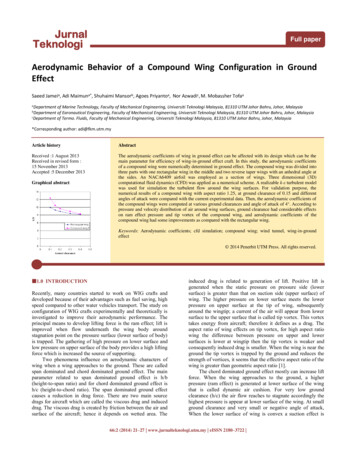
Ground viscous effect on 3D flow structure of a compound wing-in-ground effect(a) Drag coefficient(b) Lift to drag ratioFigure 2. Comparison of experimental and numerical simulation of the compound wingat ground clearance of 0.15: (a) drag coefficient; (b) lift to drag ratio.RESULTS AND DISCUSSIONPressure and Velocity Contour of the Compound WingFigures 3–6 show the pressure and velocity distribution of the compound wing for fixedand moving ground at ground clearances of 0.1 and 0.4 with an angle of attack of 4 .For both ground conditions, Figure 3 demonstrates that the ram effect on the lowersurface of the compound wing at a ground clearance of 0.1 was stronger than with aground clearance of 0.4; on the other hand, the suction effect on the upper surface at aground clearance of 0.1 was slightly stronger.The suction effect at the leading edge of the compound wing for moving groundis greater than for fixed ground at a ground clearance of 0.1, while there is no differenceat a ground clearance of 0.4 (Figure 3). There was a wider high pressure area especiallynear the trailing edge of the lower surface for moving ground at a ground clearance of0.1 (Figure 3a), which means that the recovery of pressure was slightly higher formoving ground. However, the pressure distribution shows a small increment at the endof the compound wing for fixed ground at a ground clearance of 0.4 (Figure 3b). Thisfigure shows the ground boundary layer’s effect on the pressure distributions because ofthe fixed ground condition.At a low ground clearance of 0.1, the effective height for fixed ground is smallerbecause of its displacement thickness and this causes a vent effect; hence, there waslower pressure in the flow passage between the lower side of the compound wing andground at the middle span for fixed ground, as shown in Figure 4a. Also, the stagnationpoint moved to the lower side of the compound wing as the wing approached theground. Conversely, the vent effect does not exist at a ground clearance of 0.4, and thedisplacement thickness related to fixed ground caused slightly higher pressure at thetrailing and leading edges compared to moving ground (Figure 4b).1554
Jamei et al. /International Journal of Automotive and Mechanical Engineering 9 (2014) 1550-1563Lower surface- Moving groundUpper surface- Moving groundLower surface- Fixed groundUpper surface- Fixed ground(a) h/c 0.1Lower surface- Moving groundLower surface- Fixed groundUpper surface- Moving groundUpper surface- Fixed ground(b) h/c 0.4Figure 3. Pressure coefficient contours on upper and lower surfaces of the compoundwing for moving and fixed ground with angle of attack of 4 at (a) h/c 0.1; (b) h/c 0.4.1555
Ground viscous effect on 3D flow structure of a compound wing-in-ground effectMoving groundFixed ground(a) h/c 0.1Moving groundFixed ground(b) h/c 0.4Figure 4. Pressure coefficient contour on middle span of the compound wing for movingand fixed ground with angle of attack of 4 at (a) h/c 0.1; (b) h/c 0.4.Figure 5 shows the effect of the boundary layer on the velocity distribution inthe flow passage between the compound wing and ground. This figure depicts theboundary layers at fixed ground, while they disappeared for moving ground because thespeed of the air flow and ground was the same. The velocity distribution at the middlespan of the compound wing is in contrast to the pressure distribution (Figure 4a)according to the Bernoulli equation, where there was a higher velocity in the flowpassage between the lower surface of the compound wing and fixed ground near the1556
Jamei et al. /International Journal of Automotive and Mechanical Engineering 9 (2014) 1550-1563leading edge than with moving ground. Figure 6 illustrates the pressure distribution nearthe wingtips for both conditions. In general, pressure leakages from the lower surface tothe upper surface of a wing will generate a tip vortex and spread to the downstream flowfield. This vortex is revealed as induced drag. The total drag is a summation of frictiondrag and induced drag. According to the pressure distribution at the wingtip of thecompound wing related to moving ground, the tip vortex was stronger than with fixedground and therefore the induced drag was greater.Moving groundFixed groundFigure 5. Velocity contour (m/s) on middle span of the compound wing for moving andfixed ground with angle of attack of 4 at h/c 0.1.Moving groundFixed groundFigure 6. Pressure coefficient contours near wingtip of the compound wing for movingand fixed ground with angle of attack of 4 at h/c 0.1.Aerodynamic Coefficients of the Compound WingLift CoefficientThe effects of different ground clearance on the aerodynamic coefficients of thecompound wing for moving and fixed ground at an angle of attack of 4 are shown in1557
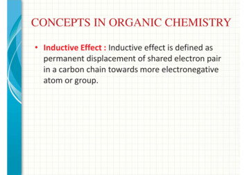
Ground viscous effect on 3D flow structure of a compound wing-in-ground effectTables 2–6 and Figures 7–9. Figure 7 illustrates a rapid increase in the lift coefficientsof the compound wing for both ground conditions as the ground clearance wasdecreased. According to the present results, at low ground clearance (h/c 0.15) the liftcoefficient shows a greater improvement related to moving ground, while at a groundclearance greater than 0.15 the lift coefficient of the compound wing is higher when theground is assumed to be fixed. This figure reveals the effect of ground viscous variedversus ground clearance. The increment of the lift coefficient of the compound wingwith moving ground compared with fixed ground was calculated by using Eq. (4) and issummarized in Table 2. The increment was valuable at a small ground clearance, whereat the ground clearance of 0.1, it was 3.5 %.C L ( Moving)Increment (%) 1(4)C L ( Fixed )Figure 7. Lift coefficient (CL) versus ground clearance at angle of attack of 4 .Table 2. Lift coefficient and its increment of the compound wing versus groundclearance at angle of attack of 4º for moving and fixed ground.Ground clearanceLift coefficient0.10.150.20.30.4Moving ground Fixed 00.337Increment ofCL (%)3.50.5-1.1-2.4-2.3Drag CoefficientThe drag coefficients of the compound wing versus ground clearance for moving andfixed ground are depicted in Figure 8. In addition, the differences of drag coefficient ofthe compound wing related to different ground boundaries were calculated by using Eq.(5) in Table 3. Figure 8 shows a small variation in the drag coefficient of both ground1558
Jamei et al. /International Journal of Automotive and Mechanical Engineering 9 (2014) 1550-1563conditions versus ground clearance, while the plot of moving ground was lower thanfixed ground. The gap between the plots reduced when the ground clearance increased.The reduction of the drag coefficient related to moving ground as compared with fixedground was in the range 4.6–2.1 %, as shown in Table 3. This reduction could be relatedto viscous drag.Reduction (%) 1 C D ( Moving)(5)C D ( Fixed )Figure 8. Drag coefficient (Kaptan, Buyruk, & Ecder) versus ground clearance at angleof attack of 4 .Table 3. Drag coefficient and its reduction of the compound wing versus groundclearance at angle of attack of 4º for moving and fixed ground.Groundclearance0.10.150.20.30.4Drag xed groundReduction ofCD ft to Drag RatioThe lift to drag ratio of the compound wing versus ground clearance is summarized inTable 4. In addition, the increment of the lift to drag ratio of the compound wing formoving ground compared with fixed ground was determined by using Eq. (6). The1559
Ground viscous effect on 3D flow structure of a compound wing-in-ground effectincrement was noticeable at low ground clearances. For example, at a ground clearanceof 0.1, the increment was 8.4 %. The trend of the lift to drag ratio of the compound wingfor both ground boundaries versus ground clearance is shown in Figure 9. This figureillustrates that the efficiency (lift to drag ratio) of the compound wing was affected bythe ground viscous effect at ground clearances lower than 0.2.Increment (%) L / D( Moving)L / D( Fixed )) 1(6)Figure 9. Lift to drag ratio (L/D) versus ground clearance at angle of attack of 4 .Table 4. Lift to drag ratio and its increment of the compound wing versus groundclearance at angle of attack of 4º for moving and fixed ground.Groundclearance0.10.150.20.30.4Lift to drag ratioMovingground13.43610.9179.8238.9208.249Fixed groundIncrement ofL/D (%)12.3910.489.638.948.298.44.22.0-0.3-0.5Moment Coefficient and Center of PressureThe variation of moment coefficients of the compound wing versus ground clearance isshown in Table 5. A moment coefficient that caused a decrease in the angle of attackwas defined as a positive moment. The increment of moment coefficient related to1560
Jamei et al. /International Journal of Automotive and Mechanical Engineering 9 (2014) 1550-1563ground boundaries was calculated by using Eq. (7) in Table 5. There is a slight variationin increment, and the maximum increment was 2.5 % at a ground clearance of 0.1. InTable 6, the increment of the distance of the center of pressure from the leading edge ofthe compound wing related to moving ground was calculated by using Eq. (8). Thisincrement was small. Based on the present results, the stability of the compound wingis not affected by the type of ground boundary.C M ( Moving)Increment (%) Increment (%) C M ( Fixed ) 1X CP / c( Moving)X CP / c( Fixed )(7) 1(8)Table 5. Moment coefficient and its increment of the compound wing versus groundclearance at angle of attack of 4º for moving and fixed ground.Groundclearance0.10.150.20.30.4Moment coefficientMovingFixed 520.0470.047Increment ofCM (%)2.51.10.0-1.0-1.0Table 6. Center of pressure and its increment of the compound wing versus groundclearance at angle of attack of 4º for moving and fixed ground.Groundclearance0.10.150.20.30.4Center of pressureMovinggroundFixed groundIncrement ofXCP/c 390-0.30.20.40.50.5CONCLUSIONSThe flow structure and the aerodynamic coefficients of a compound wing in the groundeffect were numerically investigated with respect to fixed and moving ground. Excellentperformance of the compound wing with a small ground clearance was demonstrated forboth ground conditions (h/c 0.2). The lift and drag coefficients of the compound wingshowed some differences because of the ground viscous effect related to fixed ground ascompared with moving ground. As a result, the lift to drag ratio of the compound winghad considerable variation at low ground clearances. Therefore, the ground viscouseffect could be more significant for the compound wing than for conventional wings.1561
Ground viscous effect on 3D flow structure of a compound wing-in-ground effectHowever, the moment coefficient and center of pressure of the compound wing are notaffected by the type of ground boundary, so it can be concluded that the stability of thecompound wing has no more variations. Based on the pressure and velocity contours forboth ground boundaries, the flow structure around the compound wing varied due to theground viscous effect. The moving ground does not exist in some wind tunnels.Therefore, this research confidently helps give a better understanding of the groundviscous effect on the wing-in-ground effect and can modify the results of wind tunnelsbecause, in reality, for zero air velocity there is no ground viscous effect.ACKNOWLEDGMENTSThe authors would like to thank the Ministry of Science, Technology, and Innovation(MOSTI) Malaysia for funding this research.REFERENCESAbramowski, T. (2007). Numerical investigation of airfoil in ground proximity. Journalof Theoretical and Applied Mechanics, 45, 425-436.Barber, T. J., Leonardi, E., & Archer, R. (2002). Causes for discrepancies in groundeffect analyses. Aeronautical Journal, 106, 653-667.Borello, G., Ferro, S., Limone, S., Ferro, G., Bergamini, P., & Quagliotti, F. (1999). Therole of the moving ground for automotive wind tunnel testing on race cars.Training, 2009, 04-01.Jamei, S., Maimun, A., Mansor, S., Azwadi, N., & Priyanto, A. (2011). Numericalinvestigation on performance and environmental impact of a compound wing inground effect. Paper presented at the 2 nd International Conference on FluidMechanics and Heat Transfer.Jamei, S., Maimun, A., Mansor, S., Azwadi, N., & Priyanto, A. (2012). Numericalinvestigation on aerodynamic characteristics of a compound wing-in-groundeffect. Journal of Aircraft, 49(5), 1297-1305.Jamei, S., Maimun, A., Mansor, S., Priyanto, A., Azwadi, N., & Mobassher Tofa, M.(2014). Aerodynamic behavior of a compound wing configuration in groundeffect. Jurnal Teknologi, 66(2), 21-27.Kaptan, Y., Buyruk, E., & Ecder, A. (2008). Numerical investigation of fouling oncross-flow heat exchanger tubes with conjugated heat transfer approach.International Communications in Heat and Mass Transfer, 35(9), 1153-1158.Knowles, K., Donoghue, D., & Finnis, M. (1994). A study of wings in ground effect.Paper presented at the Loughborough University Conference on VehicleAerodynamics.Launder, B. E., & Spalding, D. (1974). The numerical computation of turbulent flows.Computer Methods in Applied Mechanics and Engineering, 3(2), 269-289.Ludwig, R. D., McGregor, R. G., Blowes, D. W., Benner, S. G., & Mountjoy, K.(2002). A permeable reactive barrier for treatment of heavy metals. GroundWater, 40(1), 59-66.Marqués-Bruna, P. (2011). Engineering the race car wing: Application of the vortexpanel numerical method. Sports Engineering, 13(4), 195-204.Marshall, D., Newman, S., & Williams, C. (2010). Boundary layer effects on a wing inground-effect. Aircraft Engineering and Aerospace Technology, 82(2), 99-106.1562
Jamei et al. /International Journal of Automotive and Mechanical Engineering 9 (2014) 1550-1563Saad, I., & Bari, S. (2013). Cfd investigation of in-cylinder air flow to optimize numberof guide vanes to improve ci engine performance using higher viscous fuel.International Journal of Automotive and Mechanical Engineering, 8, 10961107.Shih, T.-H., Liou, W. W., Shabbir, A., Yang, Z., & Zhu, J. (1995). A new k-ε eddyviscosity model for high reynolds number turbulent flows. Computers & Fluids,24(3), 227-238.Tahseen, T. A., Ishak, M., & Rahman, M. M. (2013). Laminar forced convection heattransfer over staggered circular tube banks: A cfd approach. Journal ofMechanical Engineering and Sciences, 4, 418-430.Yang, W., Lin, F., & Yang, Z. (2010). Three-dimensional ground viscous effect on studyof wing-in-ground effect. Paper presented at the The third internationalconference on modelling and simulation (ICMS2010), Wuxi.Yang, W., & Yang, Z. (2009). Aerodynamic investigation of a 2d wing and flows inground effect. Chinese Journal of Computational Physics, 2, 008.Yang, Z. G., Yang, W., & Jia, Q. (2010). Ground viscous effect on 2d flow of wing inground proximity. Eng. Appl. Computational Fluid Mechanics 4(4), 521-531.Ying, C., Yang, W., & Yang, Z. (2010a). Ground viscous effect on stall of wing inground effect. Proceedings of 3rd International Conference on Modeling andSimulation, Modeling and Simulation in Industrial Application, 3, 230-233.Ying, C., Yang, W., & Yang, Z. (2010b). Numerical simulation on stall of wing inground effect. Flight Dynamics, 28(5), 9-12.Yun, L., Bliault, A., & Doo, J. (2009). Wig craft and ekranoplan: Ground effect crafttechnology. New York: DGbGkhAnhedral angleWing spanMiddle wing spanChord lengthDrag coefficientLift coefficientTip chord lengthDrag forceGeneration of turbulence kineticenergy due to buoyancyGeneration of turbulence kineticenergy due to the mean velocitygradientsHeight of trailing edge above thegroundελμμtρ1563Ground clearanceTurbulent kinetic energyLift forceLift to drag ratioWing planform areaMean rate of deformation tensorFree stream mean velocityVelocity in j-th directionEffects of compressibility onturbulenceTurbulent energy dissipationrateTaper ratio (c/ct)Air viscosityTurbulent viscosityAir density
compound wing-in-ground effect. The compound wing is divided into two parts: the middle part as the rectangular wing and the side parts that are reverse taper wings with an anhedral angle. They showed that compound wings can create a greater reduction of downwash velocity and modify the pressure distribution on the lower side, which leads