Transcription
Vol-6 Issue-2 2020IJARIIE-ISSN(O)-2395-4396DESIGN AND SIMULATION OF MARINEPROPELLER IN AN ADVANCE METALS ONSOLIDWORKSMOHAN RAM . M1, JEEVA . S2, DHAYANITHI.J3, AUGASTIN SANTHIYAGU.I4, SAMUELJONATHAN.R5ME Student (CAD/CAM Engineering)1, Assistant Professor2,3,4,5Department of Mechanical EngineeringM.A.M College of Engineering and Technology, Trichy, India.ABSTRACTThe aim of this research is to design, implement and then perform experimental comparison a MARINE PROPELLERunder various metals such as Stainless Steel 304, 316, 347. Marine propellers are made from corrosion-resistantmaterials as they are made operational directly in seawater which is a corrosion accelerator. The materials used formaking marine propeller are alloy of aluminum and stainless steel. Other popular materials used are alloys of nickel,aluminium and bronze which are 10 15 % lighter than other materials and have higher strength. The thrust from thepropeller is transmitted to move the ship through a transmission system which consists of a rotational motion generatedby the main engine crankshaft, intermediate shaft and its bearings, stern tube shaft and it’s bearing and finally by thepropeller itself. A marine propeller is constructed by sections of helicoidal surfaces acting together to rotate through thewater with a screw effect. The purpose of my project is to improve the lifetime of the product & to avoid any unavoidableincidents when running the ship. The reason why I am choosing the ides because to fulfill the factors considering forefficient ship propeller design. The factors are propeller diameter, RPM, number of blades, blade outline, angle of attackand camber, pitch/diameter ratio, stern tunnels, grouches spoilers, rudder bulb system. Here I used SOLIDWORKSsoftware to sketch, evaluate, and some other operations in it. The operations which I have done are sketch, boss-extrude,extrude-cut, fillet, lofted-surface, metals inducing, taking results, simulation, sustainability. As I mentioned earlier, Igave the detailed report of material properties, cut-section, geometry analysis, simulation , evaluation and orthographicview. Atlast I concluded, I chosen Stainless Steel 347 is the suitable material due to its higher yield strength andmaximum pressure withstand.KEYWORDS. - 2D Drafting – 3D Designing – Evaluation – Simulation – Resulting.1. INTRODUCTIONThe simulations were performed by using a 3D CAD model of a vessel of which the length is equal to about 13 m, withreference to a displacement hull condition. The results show that the non-conventional propulsion system still requiresimprovements to be competitive with respect to the traditional propeller propulsion. These improvements could make itmore advantageous than the traditional screw propulsion. Lighter hull structures together with appropriate shaped sternsand bows to increase and reduce the hydrodynamic drag force during backward and forward motion represent someaspects that have to be considered in order to improve the system performances [1]. a method to produce desired signalsfrom desired 3D paths was proposed. By tracking these signals by the controller, MUUV lead to tracking of the 3D path.The simulation results showed that in cases where MUUV tracked the generated signals by SMC with a small error, the3D path was well tracked. This point validated the derivation of desired signals from desired 3D desired paths. Moreover,in cases where the FLC tracked the signals with high error, the 3D path was also tracked with a relatively large error [2].Adjustable pitch lateral propulsion is an important control device on a ship heading. Once failure occurs, the ship willfree from manipulation and deviant off course. The assembly information model of thruster is established, and theassembly dimension chain automatically generated by the use of UG secondary development tool. The theoretical basisfor the system tolerance analysis module has been analyzed, and tolerance analysis process for the chain of thrusterassembly dimension based on the Monte Carlo method has been established. The systems select the assembly process foryoke and propeller shaft and propeller hub using the analysis application, and ultimately obtain an optimal tolerance11723www.ijariie.com1304
Vol-6 Issue-2 2020IJARIIE-ISSN(O)-2395-4396allocation scheme [3]. The AUV design was proposed in order to minimize the drag and optimize the energyconsumption according to Yucatan Caribbean Basin current conditions. An empirical and CFD tools estimation has beenused to minimize the drag as a result we get a nozzle profile with the best performance. The CFD analysis has been usedas a cost-effective process to define the parameters AUV’s hull. The torpedo body variation presented in this project isbased in literature similar design for our particular application, indeed the structure and external design allows to installexternal devices such as thrusters and sensors. The Myring profile increase the mechanical protection against unforeseenimpacts due to its geometrical properties but also the material PLA has low cost and low density [4]. There are lots to bedone to produce a fish robot which has the ability or performance of a natural fish. There are many variables and theirinter-relations that have not been studied, such as the effect of fin shape, AR, fin stiffness, angle of fin orientation, bodyshape hydrodynamics, motor torque, the fin position toward center of gravity, and some parameters such as Froude andReynolds numbers, which may all affect the swimming performance of the fish robot. Further efforts will include thesevariables and parameters along with more advanced design of control system [5]. A new economic approach to physicalmodeling of the ocean surface dynamics and interaction of irregular wind waves with a ship of arbitrary configuration inthe real-time is developed. The interactive simulation of deep ocean surface is performed by combining the Phillips wavespectrum, which is obtained on the basis of observation data, with inverse two-dimensional non-uniform fast Fouriertransform (NUFFT) technique. The interactive simulation of the immersed rigid-body dynamics is performed based onmodified Verlet algorithm. The capability of simulating the dynamic wave-body interaction in real-time is achieved byusing simple, stable, fast and computationally efficient algorithmic implementations. Despite the relative simplicity ofthe implemented physical concept, the suggested model can provide any predetermined accuracy (within the frameworkof the deep-water and open-water assumptions) by refinement the grids covering the sea surface and the ship hull. Thedescribed computational method does not impose restrictions [6]. A new economic approach to physical modeling of theocean surface dynamics and interaction of irregular wind waves with a ship of arbitrary configuration in the real-time isdeveloped. The interactive simulation of deep ocean surface is performed by combining the Phillips wave spectrum,which is obtained on the basis of observation data, with inverse two-dimensional non-uniform fast Fourier transform(NUFFT) technique. The interactive simulation of the immersed rigid-body dynamics is performed based on modifiedVerlet algorithm. The capability of simulating the dynamic wave-body interaction in real-time is achieved by usingsimple, stable, fast and computationally efficient algorithmic implementations. Despite the relative simplicity of theimplemented physical concept, the suggested model can provide any predetermined accuracy (within the framework ofthe deep-water and open-water assumptions) by refinement the grids covering the sea surface and the ship hull. Thedescribed computational method does not impose restrictions desired rated power, with the help of genetic algorithmselection of blade profiles. , it is more cost effective to manufacture by selecting untwisted blade profile. The influence ofnacelle shape on the turbine performance is also discussed in the present paper, namely the traditional cylindrical shapeand NACA profiled shape. Both different nacelles can house the same size generator [7]. Instead of decoupling the glidermodel into two models, lateral and longitudinal, the coupled model has been designed. In addition, the presence of thewater currents as a disturbance is included in the mathematical model of the glider. Furthermore, the hydrodynamics ofthe glider's structure have been analyzed by using CFD. Thus, the analysis of the glider's pressure contours, velocityvectors, and dynamics forces like the drag, The CFD analysis shows that the glider design is acceptable due to a low dragcoefficient. In addition, the comparison of the coefficients between the CFD and Strip theory shows that the glider modelis acceptable due to the small differences between the coefficients produced by these methods [8]. A methodology tosimulate SPIF into the SolidWorks has been successfully devised and it has been demonstrated that this environment canbe employed for a correct definition of the process variables and the material properties, especially for plastic behaviour.The results herein obtained show that the stress values are not large and that the achieved strain should be greater fromthe forming goal viewpoint of Incremental Sheet Forming Processes. For this reason, the tool path should be suitablymodified, increasing the Z coordinate. Anyway, the agreement of the simulation results with the experimental onesexisting in literature predicts that the technique herein presented will lead to a good evaluation of the process. Anotherconsideration that should be taken into account in future is the friction phenomenon [9]. The results of individual bendingcoefficients obtained indicate that for soft material in bottom layer the bendability is higher. This can be explained by thefact that the soft material shows higher deflection under tensile stress than the hard one. As a result the deflections beforereaching MOR are higher than those for inverse compositions. Such knowledge may become the basis for laminatedmaterial design. This way designed materials might have practical use wherever good bendability as well as goodstructural strength parameters are required [10]. In this present work I designed a marine propeller in Stainless Steelgrades (306, 314,347). Here I done the 3D modeling, simulation, sustainability, comparing the mechanical properties andhas been properties of Stainless Steel-347 is satisfied.2. SELECTION OF MATERIAL11723www.ijariie.com1305
Vol-6 Issue-2 2020IJARIIE-ISSN(O)-2395-4396Alloy 347 (S34700) is stabilized stainless steel plate which offers as its main advantage an excellent resistance tointergranular corrosion following exposure to temperatures in the chromium carbide precipitation range from 800 to1500 F (427 to 816 C). Alloy 347 stainless steel plate is stabilized by the addition of columbium and tantalum.Alloy 347 stainless steel plate is also advantageous for high temperature service because of its good mechanicalproperties. Alloy 347 stainless steel plate offers higher creep and stress rupture properties than Alloy 304 and,particularly, Alloy 304L, which might also be considered for exposures where sensitization and intergranular corrosionare concerns.2.1 Material CompositionNAME OF THE304316347STAINLESS STEELMATERIAL COMPOSITIONNAME OF THECONTAINMENT bdenum-2%Cb Ta---10xCTable-1: Material composition of Stainless Steel 304, 316, 3473. DESIGN PROCEDURE3.1 To Draw The 3D Modeling Of MARINE PROPELLER: Click New option – Advanced – Part – Click OK.Choose Plain white background.Select front plane.Select IPS measurement and increase the image quality option in higher definition to improve the quality ofdesign.Draw the circle with diameter of 1000 inches.Boss-Extrude and give the diameter of 1250 inches and click Mid-plane to set the axis at the midpoint of theobject.Top-plane – Reference geometry – Select new plane – Offset distance-375 inches - Click OK.Smart Dimension – Select the centerline and drawn line evenly and the give the pitch angle 48 0.Repeat the procedure but now the Offset distance is 2500 inches.View Orientation – Normal To – Draw the centerline with any measurement – Draw one cross-line with 4000inches which it wants to coincides with centerline.Repeat this procedure another plane but now the line should be straight line with 4000 inches.Hide the Planes.Surface – Lofted surface – Select the edges of the two lines which created on the planes – Click OK.11723www.ijariie.com1306
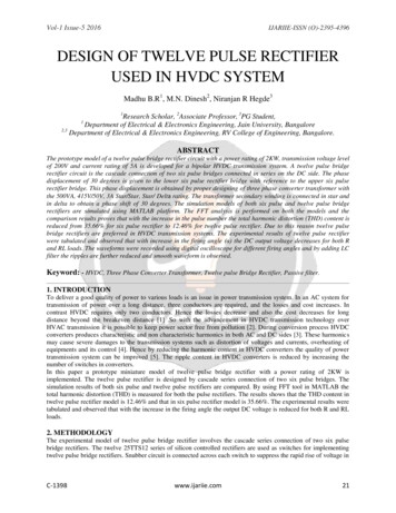
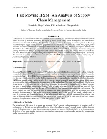
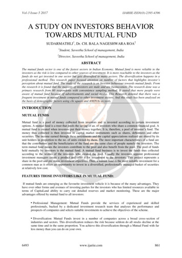
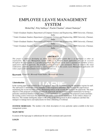
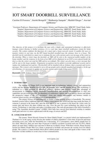
Vol-6 Issue-2 2020IJARIIE-ISSN(O)-2395-4396 Front plane – Features – Reference geometry – Plane – Offset distance 3000 inches. View orientation – Normal To – Click the spline option and draw the fin – Exit sketch. Features – Curves – Project curve – Select On Faces – Select the sketch which we drawn on the plane and theselect lofted surface – Reverse direction. Hid the plane. Insert – Surfaces – Trim surface – Select the surface which we want to trim – Click OK. Insert - Boss-extrude – Thichness-10 inches. Fillet – Select the edges of the thickened surface and bottom of the fin– Give the value of 10 inches forthickened fin and 30 inches for bottom of the fin – Click OK. Features – Linear pattern – Circular pattern – Bodies – Select the whole Body - Give the parameters such asDegree-3600 and Number of fins-4 ( To get the high propulsive efficiency. Select right plane – View orientation – Normal to. Draw the line from top edge to midpoint and extend it two time One is straight and another is on top. Click Spline – Draw the straight line from the first and last point of the extended line. Click the centre-point – Click Horizontal – Ok. Smart Dimension – Give the value for straight from cenre-872 inches and for top extended line-72 inches. Feature – Revolved Boss/Base – Select the extended straight line – Click OK. Insert – Features – Dome – Select font face and give value-25 inches – Click OK. Go to backside of the Hub. Draw the circle with 700 inches. Features – Extruded cut – Give the vaue-1250 inches. Finalize the Design.3.2 To Simulate The 3D Modeling Of MARINE PROPELLER: SolidWorks Add-Ins – SolidWorks Simulation – Simulation – New study.Click Static – Click OK.Select the material which we want to test.Fixtures – Select the fixed part of the geometry – Click OK.External Loads – Pressure – Apply the maximum pressure of the material where it is needed – Reverse direction– Click OK. Mesh – Select the level of mesh – Give the meshing parameters – Click OK – Ensure the meshing is done. Run the result.4. EXPERIMENTAL WORKIn my project experimental work is meant by designing the MARINE PROPELLER in SolidWorks software. IN thisresearch I done the works like 2D drafting, 3D modeling, evaluation, taking analysis report, and then simulation. Here Iinclude the orthographic view, simulated diagram (Von-Mises and Displacement).4.1 ORTHOGRAPHIC VIEW:Fig-1: Front Plane of Marine Propeller11723Fig-2: Top Plane of Marine Propellerwww.ijariie.com1307
Vol-6 Issue-2 2020IJARIIE-ISSN(O)-2395-4396Fig-3: Left Plane of Marine PropellerFig-4: Trimetric Plane of Marine Propeller4.2 Mass Properties of Stainless Steel Density 0.29 pounds per cubic inch Mass 332872901.73 pounds Volume 1151736580.78 cubic inches Surface area 34144327.31 square inches Center of mass: ( inches )X 0.00Y 0.00Z -313.36 Principal axes of inertia and principal moments of inertia: ( pounds * square inches )Taken at the center of mass.Ix ( 0.00, 1.00, 0.00)Px 225363743186495.50Iy (-1.00, 0.00, 0.00)Py 225363743186495.50Iz ( 0.00, 0.00, 1.00)Pz 260706124851174.87 Moments of inertia: ( pounds * square inches )Taken at the center of mass and aligned with the output coordinate system.Lxx 225363743201222.37Lxy -0.77Lxz 991522060.39Lyx -0.77Lyz 0.17Lyy 225363743199586.00Lzx 991522060.39Lzz 260706124823357.50Lzy 0.17 Moments of inertia: ( pounds * square inches )Taken at the output coordinate system.Ixx 258050124539149.84Ixz 1222786786.01Iyx -0.77Ixy -0.77Iyy 258050124539149.75Iyz 0.02Izx 1222786786.0111723Izy 0.02www.ijariie.com1308
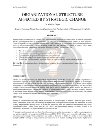
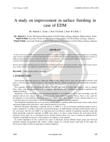
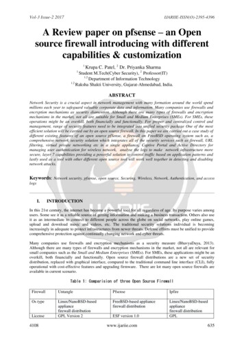
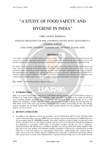
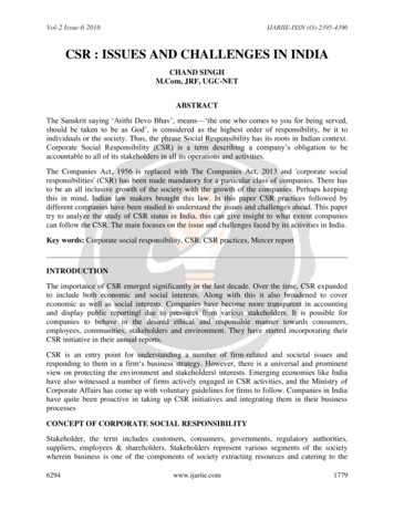
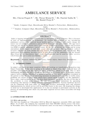
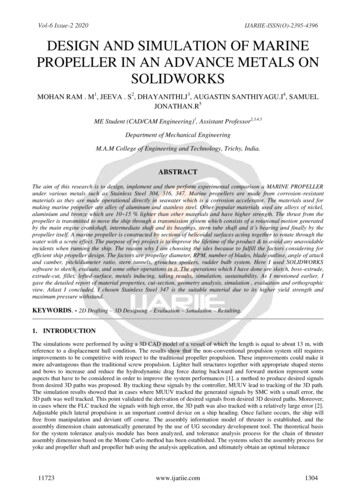
Vol-6 Issue-2 2020IJARIIE-ISSN(O)-2395-4396Izz 260706124824993.755. SIMULATED DIAGRAM5.1 STAINLESS STEEL (304)Fig-5 Von-Mises for SS304Fig-6 Displacement for SS3045.2 STAINLESS STEEL (316)Fig-7 Von-Mises for SS316Fig-8 Displacement for SS3165.3 STAINLESS STEEL (347)Fig-9 Von-Mises for SS34711723Fig-10 Displacement for SS347www.ijariie.com1309
Vol-6 Issue-2 2020IJARIIE-ISSN(O)-2395-43966. RESULTS AND DISCUSSIONAs the table concludes increased comparative study of mechanical properties. There is a step-by-step increment inmaximum pressure, elastic modulus, tensile strength, yield strength. As it shows the increment of properties in StainlessSteel 304 – 316 – 437. Here I enclosed the comparative property table hName of theStainless Steel30431634719000 psi80001.9 e 0110.29 N/A517017000Kg/m3N/m220000 psi80001.9299 e 0110.27 N/A580000000Kg/m3N/m230000 psi80001.950 e 0110.27 N/A654999998.5Kg/m3N/m2Table-2: Material comparison of Stainless Steel 304, 316, 3472.068 e 002N/m21.379 e 002N/m22.75 e 002N/m27. CONCLUSIONSolidWorks grades with Stainless Steel 304, 316, 347 was successfully designed via SolidWorks software. Testresults revealed that grade 347 enhances the mechanical properties of Stainless Steel. There is a increment ofmechanical properties like maximum pressure, elastic modulus, tensile strength, yield strength one-by-one which isshown in results and discussion chapter. Hence It is purely done by own through SolidWorks software.8. REFERENCE1) Roberto Muscia. Study of a vibrating propulsion system for marine vessels: Evaluation of the efficiency for a boat13 m long.2) Ehsan Zakeri. Robust sliding mode control of a mini unmanned underwater vehicle equipped with a newarrangement of water jet propulsions. Applied Ocean Research 59 (2016) 521-542.3) ShuYing Tang. Analysis on virtual assembly tolerance for pitch-adjustable lateral propulsion device. Procedia CIRP27 ( 2015 ) 131 – 136.4) Llanez C. Ignacio. Optimized design of an autonomous underwater vehicle, for exploration in the Caribbean Sea.Ocean Engineering 187 (2019) 106184.5) Patar Ebenezer Sitorus. Design and Implementation of Paired Pectoral Fins Locomotion of Labriform Fish Appliedto a Fish Robot. Journal of Bionic Engineering 6 (2009) 37–45.6) Alexandra L. Physically-based method for real-time modelling of ship motion in7) irregular waves. Ocean Engineering 195 (2020) 106686.8) Jing Liu. The effects of blade twist and nacelle shape on the performance of horizontal axis tidal current turbines.Applied Ocean research 64 (2017) 58 – 59.9) Khalid Isa. A hybrid-driven underwater glider model, hydrodynamics estimation, and an analysis of the motioncontrol. Ocean Engineering 81 (2014) 111 – 129.10) L.M. Gómez-Lópeza. Simulation and Modeling of Single Point Incremental Forming Processes within a SolidworksEnvironment. Procedia Engineering 63 ( 2013 ) 632 – 641.11) Milan Gaf. Stress simulation in layered wood-based materials under mechanical loading. Material and Design 87(2015) 1065 – 1071.11723www.ijariie.com1310
efficient ship propeller design. The factors are propeller diameter, RPM, number of blades, blade outline, angle of attack and camber, pitch/diameter ratio, stern tunnels, grouches spoilers, rudder bulb system. Here I used SOLIDWORKS software to sketch, evaluate, and some other operations in it.