Transcription
XC6209 SeriesETR0306 009High Speed LDO Regulators Low ESR Cap.Compatible,Output ON/OFFControl GENERAL DESCRIPTIONThe XC6209 series are highly precise, low noise, positive voltage LDO regulators manufactured using CMOS processes. Theseries achieves high ripple rejection and low dropout and consists of a voltage reference, an error amplifier, a current limiterand a phase compensation circuit plus a driver transistor.Output voltage is selectable in 0.05V increments within a range of 0.9V 6.0V.The series is also compatible with low ESR ceramic capacitors which give added output stability. This stability can bemaintained even during load fluctuations due to the excellent transient response of the series. The current limiter's foldbackcircuit also operates as a short protect for the output current limiter and the output pin.The CE function enables the output to be turned off, resulting in greatly reduced power consumption. APPLICATIONS FEATURES Smart phones / Mobile phonesMaximum Output Current Portable game consoles Digital still cameras / Camcorders Digital audio equipments Reference voltage sources Multi-function power suppliesDropout VoltageMaximum Operating VoltageOutput Voltage RangeHighly AccurateLow Power ConsumptionStandby CurrentHigh Ripple RejectionOperating Ambient TemperatureLow ESR CapacitorCompatiblePackagesEnvironmentally Friendly TYPICAL APPLICATION CIRCUIT: 150mA(300mA XC6209 E to H types): 60mV @ 30mA: 200mV @ 100mA: 2.0V 10V: 0.9V 6.0V(0.05V increments): 2% (VOUT 1.5V) 30mV (VOUT 1.5V): 25μA (TYP.): Less than 0.1μA (TYP.): 70dB (10kHz): -40 85 : Ceramic capacitor: SOT-25USP-6BSOT-89-5: EU RoHS Compliant, Pb Free TYPICAL PERFORMANCECHARACTERISTICS1/30
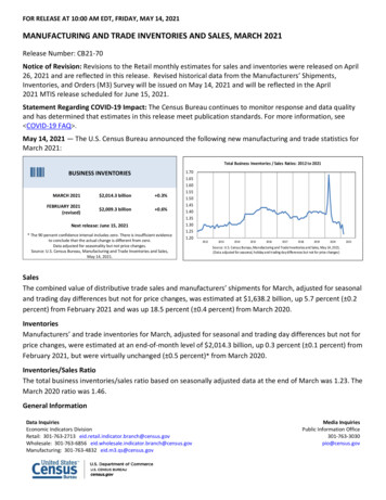
XC6209 Series PIN CONFIGURATIONCE 61 VINVSS 52 NC3 VOUTNC 4USP-6B(BOTTOM VIEW)*The dissipation pad for the USP-6Bpackage should be solder-plated inrecommended mount pattern and metalmasking so as to enhance mountingstrength and heat release. If the padneeds to be connected to other pins, itshould be connected to the VSS pin. PIN ASSIGNMENTPIN NUMBERSOT-25123PIN NAMEFUNCTIONSVINVSSCEInputGroundON/OFF ControlSOT-89-5423USP-6B156412,4NCNo Connection553VOUTOutput FUNCTIONSTYPEType A, B, E, FType C, D, G, HH High LevelL Low Level2/30CEHLHLOPERATIONAL STATEONOFFOFFON
XC6209Series PRODUCT CLASSIFICATION Ordering TEMSYMBOLABCType of RegulatorCE Pin Logic①DEFGHOutput Voltage②③09 6030 602Output VoltageAccuracy④1AB⑤⑥-⑦(*4)Packages(Order Unit)MRMR-GPRPR-GDRDR-GDESCRIPTION150mA, Active High, Pull-down resistor built-in (*2)(Semi-custom)150mA, Active High, No pull-down resistor(Standard)150mA, Active Low, Pull-up resistor built-in (*2)(Semi-custom)150mA, Active Low, No pull-up resistor(Semi-custom)300mA (*1), Active High, Pull-down resistor built-in (*2)(Semi-custom)300mA ( *1), Active High, No pull-down resistor(Standard)300mA (*1), Active Low, Pull-up resistor built-in (*2)(Semi-custom)300mA (*1), Active Low, No pull-up resistor(Semi-custom)Output Voltage Range: 0.9V 6.0Ve.g. : 3.0V ② 3, ③ 0For 1% product, output voltage range is 3.0V 6.0V.0.1V increments, Accuracy: 2% (*3)e.g.: 2.80V ② 2, ③ 8, ④ 20.1V increments, Accuracy: 1%e.g.: 3.00V ② 3, ③ 0, ④ 10.05V increments, Accuracy: 2% (*3)e.g.: 2.85V ② 2, ③ 8, ④ A0.05V increments, Accuracy: 1%e.g.: 3.05V ② 3, ③ 0, ④ BSOT-25 (3,000/Reel)SOT-25 (3,000/Reel)SOT-89-5 (1,000/Reel)SOT-89-5 (1,000/Reel)USP-6B (3,000/Reel)USP-6B (3,000/Reel)(*1)The maximum output current of type E H depends on setting output voltage.With the pull-up resistor or pull-down resistor built-in types, the supply current during operation will increase by VIN / 2MΩ (TYP.).(*3)The output voltage accuracy is 30mV at VOUT 1.5V.(*4)The “-G” suffix denotes Halogen and Antimony free as well as being fully EU RoHS compliant.(*2)3/30
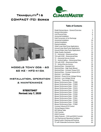
XC6209 Series BLOCK DIAGRAMXC6209 Type A, EXC6209 Type B, D, F, HXC6209 Type C, G* Diodes inside the circuits are ESD protection diodes and parasitic diodes.4/30
XC6209Series ABSOLUTE MAXIMUM RATINGSTa 25 PARAMETERInput VoltageOutput CurrentOutput VoltageCE Input VoltageSYMBOLVINIOUTVOUTVCESOT-25Power DissipationSOT-89-5PdUSP-6BOperating Ambient TemperatureStorage TemperatureToprTstgRATINGS12.0500 (*1)VSS - 0.3 VIN 0.3VSS - 0.3 VIN 0.3250600(PCB mounted)(*2)5001300(PCB mounted)(*2)1201000(PCB mounted)(*2)-40 85-55 125UNITSVmAVVmW All voltages are described based on the VSS.(*1)IOUT Pd/(VIN-VOUT)(*2)This is a reference data taken by using the test board. Please refer to page 25 to 27 for details.5/30
XC6209 Series ELECTRICAL CHARACTERISTICSXC6209 (Type A, B)PARAMETEROutput Voltage (2%)(*5)Output Voltage (1%)(*6)SYMBOLVOUT(E) (*3)CONDITIONSIOUT 30mAMaximum Output CurrentIOUTMAX-Load Regulation VOUT1mA IOUT 100mADropout Voltage (*4)MIN.VOUT(T)(*2) 0.98VOUT(T)(*2) 0.99150-TYP.VOUT(T) (*2)MAX.VOUT(T)(*2) 1.02VOUT(T)(*2) 1.01Ta 25 UNITS CIRCUITV①--mA①1550mV①Vdif1IOUT 30mAE-1mVVdif2IOUT 100mAE-2mVSupply Current(Type A)Supply Current(Type B)IDDStand-by CurrentISTBLine Regulation VOUT/( VIN・VOUT)VCE VIN VOUT(T) 1.0VWhen VOUT 0.95V, VIN VCE 2.0VVIN VOUT(T) 1.0V,VCE VSSWhen VOUT 0.95V, VIN 2.0VVOUT(T) 1.0V VIN 10VWhen VOUT 0.95,2.0V VIN 10VIOUT 30mAWhen VOUT 1.75V, IOUT /V①2-10V--100-ppm/ ①-70-dB④-300-mA①-50-mA①Input VoltageVINOutput VoltageTemperatureCharacteristics VOUT/( Topr・VOUT)Power SupplyRejection RatioPSRRCurrent LimitIlimShort CurrentISHORTCE ”H” Level ��IOUT 30mA-40 Topr 85 VIN [VOUT(T) 1.0]V 1.0Vp-pACWhen VOUT 1.5V, VIN 2.5V 1.0Vp-pACIOUT 50mA, f 10kHzVIN VOUT(T) 1.0V, VCE VSSWhen VOUT 1.75, VIN VOUT(T) 2.0VVIN VOUT(T) 1.0V, VCE VSSWhen VOUT 1.75, VIN VOUT(T) 2.0VCE ”L” Level VoltageVCEL-CE ”H” Level Current(Type A)CE ”H” Level Current(Type B)ICEHVIN VCE VOUT(T) 1.0V,When VOUT 0.95V, VIN VCE 2.0VCE ”L” Level CurrentICELVIN VOUT(T) 1.0V,VCE VSSWhen VOUT 0.95V, VIN 2.0V*1: Unless otherwise stated, VIN VOUT(T) 1.0V.-0.1-0.10.1-0.1If VOUT is less than 0.95V, VIN 2.0V.*2: VOUT(T) is Nominal output voltage*3: VOUT(E) is Effective output voltage(I.e. the output voltage when "VOUT(T) 1.0V" is provided at the VIN pin while maintaining a certain IOUT value).*4: Vdif {VIN1-VOUT1}VOUT1 is the voltage equal to 98% of the output voltage whenever an amply stabilized VOUT(T) 1.0V is input for every IOUT.VIN1 is the input voltage when VOUT1 appears while input voltage is gradually decreased.*5: If VOUT(T) is less than 1.45V, VOUT(T) -30mV (MIN.), VOUT(T) 30mV (MAX.)*6: Only for the VOUT(T) is more than 3.0V products.6/30
XC6209Series ELECTRICAL CHARACTERISTICSTa 25 XC6209 (Type C, D)PARAMETEROutputVoltage (*5)(2%)Output Voltage (*6)(1%)SYMBOLVOUT(E) (*3)CONDITIONSIOUT 30mAMaximum Output CurrentIOUTMAX-Load Regulation VOUTVdif1Vdif2Dropout Voltage (*4)Supply Current(Type C)Supply Current(Type D)IDDStand-by CurrentISTBLine Regulation VOUT/( VIN・VOUT)Input VoltageVINOutput VoltageTemperatureCharacteristics VOUT/( Topr・VOUT)MIN.VOUT(T)(*2) 0.98VOUT(T)(*2) ��μA②VOUT(T)(*2) 1.02VOUT(T)(*2) 1.01150-1mA IOUT 100mA-15IOUT 30mA-E-1IOUT 100mA-E-2VIN VOUT(T) 1.0VWhen VOUT 0.95V, VIN 2.0VVCE VSS-28UNITS55-2550VIN VOUT(T) 1.0V, VCE VINWhen VOUT 0.95V, VIN VCE 2.0V-0.010.10μA②VOUT(T) 1.0V VIN 10VVOUT 0.95V is 2.0V VIN 10VIOUT 30mAWhen VOUT 1.75V, IOUT 10mA-0.010.20%/V①-2-10V-IOUT 30mA-40 Topr 85 - 100-ppm/ ①VIN [VOUT(T) 1.0]V 1.0Vp-pACWhen VOUT 1.5V, VIN 2.5V 1.0Vp-pACIOUT 50mA, f 10kHz-70-dB④Power SupplyRejection RatioPSRRCurrent LimitIlimVIN VOUT(T) 1.0V, VCE VSSWhen VOUT 1.75V, VIN VOUT(T) 2.0V-300-mA①Short CurrentISHORTVIN VOUT(T) 1.0V, VCE VSSWhen VOUT 1.75V, VIN VOUT(T) 2.0V-50-mA①CE "H" Level VoltageVCEH-1.6-VINV①CE "L" Level VoltageVCEL---0.25V①CE "H" Level CurrentICEHVCE VIN VOUT(T) 1.0VWhen VOUT 0.95V, VCE VIN 2.0V-0.1-0.1μA②-5.0--0.8ICELVIN VOUT(T) 1.0V, VCE VSSWhen VOUT 0.95V, VIN 2.0VμA②CE "L" Level Current(Type C)CE "L" Level Current(Type D)*1: Unless otherwise stated, VIN VOUT(T) 1.0V.-0.1-0.1If VOUT is less than 0.95V, VIN 2.0V.*2: VOUT(T) is Nominal output voltage*3: VOUT(E) is Effective output voltage(I.e. the output voltage when "VOUT(T) 1.0V" is provided at the VIN pin while maintaining a certain IOUT value).*4: Vdif {VIN1-VOUT1}VOUT1 is the voltage equal to 98% of the output voltage whenever an amply stabilized VOUT(T) 1.0V is input for every IOUT.VIN1 is the input voltage when VOUT1 appears while input voltage is gradually decreased.*5: If VOUT(T) is less than 1.45V, VOUT(T) -30mV (MIN.), VOUT(T) 30mV (MAX.)*6: Only for the VOUT(T) is more than 3.0V products.7/30
XC6209 Series ELECTRICAL CHARACTERISTICS (Continued)XC6209 (Type E,F)PARAMETEROutput Voltage (2%)(*5)SYMBOLCONDITIONSVOUT(E) (*3)IOUT 30mAIOUTMAXVIN E-3(*7)Load Regulation VOUTLoad Regulation 2 VOUT2Output Voltage (1%)(*6)Maximum Output CurrentDropout Voltage �E-4-1mA IOUT 100mA-1550mV①1mA IOUT 300mA--100mV①Vdif1IOUT 30mAE-1mVVdif2IOUT 100mAE-2mVSupply Current(Type E)Supply Current(Type F)IDDStand-by CurrentISTBLine Regulation VOUT /( VIN・VOUT)Input VoltageVINOutput VoltageTemperatureCharacteristics VOUT /( Topr・VOUT)Power SupplyRejection RatioPSRRCurrent LimitIlimShort CurrentISHORTCE ”H” Level VoltageVCEH-1.6-CE ”L” Level VoltageVCEL---CE ”H” Level Current(Type E)CE ”H” Level Current(Type F)0.8-5.0ICEHVIN VCE VOUT(T) 1.0VWhen VOUT 0.95V, VIN VCE 2.0V-0.1-0.1CE ”L” Level CurrentICEL-0.1-0.128552550-0.01-IOUT 30mA-40 Topr 85 VCE VIN VOUT(T) 1.0VWhen VOUT 0.95V, VCE VIN 2.0VVIN VOUT(T) 1.0V, VCE VSSWhen VOUT 0.95V, VCE VIN 2.0VVOUT(T) 1.0V VIN 10VWhen VOUT 0.95V, 2.0V VIN 10VIOUT 30mAVOUT 1.75V, IOUT 10mAVIN {VOUT(T) 1.0}V 1.0Vp-pAC,When VOUT 1.5V, VIN 2.5V 1.0Vp-pAC,IOUT 50mA, f 10kHzVIN VOUT(T) 1.0V, VCE VIN,When VOUT 1.75V, VIN VOUT(T) 2.0VVIN VOUT(T) 1.0V, VCE VIN,When VOUT 1.75V, VIN VOUT(T) 2.0VVIN VOUT(T) 1.0V, VCE VSSWhen VOUT 0.95V, VIN 2.0V*1: Unless otherwise stated, VIN VOUT(T) 1.0V.-②0.10μA②0.010.20%/V①2-10V--100-ppm/ ��μA②If VOUT is less than 0.95V, VIN 2.0V.*3: VOUT(E) is Effective output voltage(I.e. the output voltage when "VOUT(T) 1.0V" is provided at the VIN pin while maintaining a certain IOUT value).*4: Vdif {VIN1-VOUT1}VOUT1 is the voltage equal to 98% of the output voltage whenever an amply stabilized VOUT(T) 1.0V is input for every IOUT.VIN1 is the input voltage when VOUT1 appears while input voltage is gradually decreased.*5: If VOUT(T) is less than 1.45V, VOUT(T) -30mV (MIN.), VOUT(T) 30mV (MAX.)*6: Only for the VOUT(T) is more than 3.0V products.*7: Please refer to the “Dropout Voltage” table.①μA*2: VOUT(T) is Nominal output voltage8/30Ta 25 UNITS CIRCUIT
XC6209Series ELECTRICAL CHARACTERISTICS (Continued)Ta 25 XC6209 (Type G, H)PARAMETEROutputVoltage (*5)(2%)SYMBOLCONDITIONSVOUT(E) (*3)IOUT 30mAIOUTMAXVIN E-3 (*7)Load Regulation VOUTLoad Regulation 2 VOUT2Output Voltage (*6)(1%)Maximum Output CurrentDropout Voltage (*4)MIN.VOUT(T)(*2) 0.98VOUT(T)(*2) 0.99TYP.VOUT(T)(*2)MAX.VOUT(T)(*2) 1.02VOUT(T)(*2) 1.01CIRCUITV①mA①E-4-1mA IOUT 100mA-1550mV①1mA IOUT 300mA--100mV①Vdif1IOUT 30mA-E-1Vdif2IOUT 100mA-E-2mV①μA②Supply Current(Type G)Supply Current(Type H)IDDStand-by CurrentISTBLine Regulation VOUT/( VIN・VOUT)Input VoltageVINOutput VoltageTemperatureCharacteristics VOUT/( Topr・VOUT)Power SupplyRejection RatioPSRRCurrent Limit-UNITS-2855-2550VIN VOUT(T) 1.0V, VCE VINWhen VOUT 0.95V, VCE VIN 2.0V-0.010.10μA②VOUT(T) 1.0V VIN 10VWhen VOUT 0.95V, 2.0V VIN 10VIOUT 30mAWhen VOUT 1.75V, IOUT 10mA-0.010.20%/V①-2-10V-IOUT 30mA-40 Topr 85 - 100-ppm/ ①VIN [VOUT(T) 1.0]V 1.0Vp-pACWhen VOUT 1.5V, VIN 2.5V 1.0Vp-pACIOUT 50mA, f 10kHz-70-dB④IlimVIN VOUT(T) 1.0V, VCE VSSWhen VOUT 1.75V, VIN VOUT(T) 2.0V-380-mA①Short CurrentISHORTVIN VOUT(T) 1.0V, VOUT VSSWhen VOUT 1.75V, VIN VOUT(T) 2.0V-50-mA①CE ”H” Level VoltageVCEH-1.6-VINV①CE ”L” Level VoltageVCEL---0.25V①CE ”H” Level CurrentICEHVCE VIN VOUT(T) 1.0VWhen VOUT 0.95V, VCE VIN 2.0V-0.1-0.1μA②CE"L" Level Current(Type G)CE"L" Level Current(Type H)VIN VOUT(T) 1.0V, VCE VSSWhen VOUT 0.95V, VIN 2.0V-5.0--0.8ICELμA②-0.1-0.1VIN VOUT(T) 1.0VWhen VOUT 0.95V, VIN 2.0V, VCE VSS*1: Unless otherwise stated, VIN VOUT(T) 1.0V.If VOUT is less than 0.95V, VIN 2.0V.*2: VOUT(T) is Nominal output voltage*3: VOUT(E) is Effective output voltage(I.e. the output voltage when "VOUT(T) 1.0V" is provided at the VIN pin while maintaining a certain IOUT value).*4: Vdif {VIN1-VOUT1}VOUT1 is the voltage equal to 98% of the output voltage whenever an amply stabilized VOUT(T) 1.0V is input for every IOUT.VIN1 is the input voltage when VOUT1 appears while input voltage is gradually decreased.*5: If VOUT(T) is less than 1.45V, VOUT(T) -30mV (MIN.), VOUT(T) 30mV (MAX.)*6: Only for the VOUT(T) is more than 3.0V products.*7: Please refer to the “Dropout Voltage” table.9/30
XC6209 Series ELECTRICAL CHARACTERISTICS (Continued) Dropout VoltageVoltage Accuracy 2% 0.90 *0.95 *1.00 *1.05 *1.10 *1.15 *1.20 *1.25 *1.30 *1.35 *1.40 *1.45 *1.50 *1.55 *1.60 *1.65 *1.70 *1.75 *1.80 *1.85 *1.90 *1.95 03.253.303.353.403.453.503.55E-0OUTPUT VOLTAGE 4793.621* The input voltage 2.0V (MIN.) is needed to operate the IC.10/30E-1DROPOUT VOLTAGE 1 (mV)(IOUT 30mA)Vdif1TYP.MAX.Ta 25 E-2DROPOUT VOLTAGE 2 (mV)(IOUT 02.0V-VOUT(T) of dropout voltage is needed at minimum.
XC6209Series ELECTRICAL CHARACTERISTICS (Continued) Dropout Voltage (Continued)Voltage Accuracy 2% UTPUT VOLTAGE .8806.120Ta 25 E-1DROPOUT VOLTAGE 1 (mV)(IOUT 30mA)Vdif1TYP.MAX.E-2DROPOUT VOLTAGE 2 (mV)(IOUT 30
XC6209 Series ELECTRICAL CHARACTERISTICS (Continued) Output VoltageVoltage Accuracy 1% productsE-0OUTPUT VOLTAGE .3564.4444.4054.4944.4554.545SYMBOLNOMINALOUTPUT LOUTPUT 605.655.705.755.805.855.905.956.00E-0OUTPUT VOLTAGE .9095.9596.0106.060 ConditionsSYMBOLCONDITIONS, SPEC .NOMINAL OUTPUT VOLTAGE (V)0.90 0.951.00 1.051.10 1.151.20 1.251.30 1.351.40 1.451.50 1.952.00 6.00* VOUT(T) is Nominal output voltage value.12/30E-3INPUT VOLTAGE (V)VIN2.52.52.62.72.82.93.0VOUT(T) 1.0E-4MAXIMUM OUTPUT CURRENT (mA)MIN.260260270290300
XC6209Series OPERATIONAL EXPLANATIONOutput voltage control with the XC6209 series:The voltage divided by resistors R1 & R2 is compared with the internalreference voltage by the error amplifier.The P-channel MOSFET, which is connected to the VOUT pin, is thendriven by the subsequent output signal. The output voltage at the VOUTpin is controlled & stabilized by a system of negative feedback.The current limit circuit and short protect circuit operate in relation tothe level of output current. Further, the IC's internal circuitry can beshutdown via the CE pin's signal. Low ESR Capacitors With the XC6209 series, a stable output voltage is achievable even if used with low ESR capacitors as a phase compensationcircuit is built-in. In order to ensure the effectiveness of the phase compensation, we suggest that an output capacitor (CL) isconnected as close as possible to the output pin (VOUT) and the VSS pin. Please use an output capacitor with a capacitancevalue of at least 1μF. Also, please connect an input capacitor (CIN) of 1μF between the VIN pin and the VSS pin in order toensure a stable power input.Stable phase compensation may not be ensured if the capacitor runs out capacitance when depending on bias andtemperature. In case the capacitor depends on the bias and temperature, please make sure the capacitor can ensure theactual capacitance. Current Limiter, Short-Circuit Protection The XC6209 series includes a combination of a fixed current limiter circuit & a foldback circuit, which aid the operations of thecurrent limiter and circuit protection. When the load current reaches the current limit level, the fixed current limiter circuitoperates and output voltage drops. As a result of this drop in output voltage, the foldback circuit operates, output voltagedrops further and output current decreases. When the output pin is shorted, a current of about 50mA flows. CE Pin The IC's internal circuitry can be shutdown via the signal from the CE pin with the XC6209 series. In shutdown mode, outputat the VOUT pin will be pulled down to the VSS level via R1 & R2. The operational logic of the IC's CE pin is selectable (pleaserefer to the selection guide). Note that as the standard XC6209B type is ' Active High /No Pull Down', operations will becomeunstable with the CE pin open. Although the CE pin is equal to an inverter input with CMOS hysteresis, with either the pull-upor pull-down options, the CE pin input current will increase when the IC’s in operation.We suggest that you use this IC with either a VIN voltage or a VSS voltage input at the CE pin. If this IC is used with thecorrect specifications for the CE pin, the IC will operate normally. However, supply current may increase as a result of throughcurrent in the IC's internal circuitry NOTES ON USE1. For temporary, transitional voltage drop or voltage rising phenomenon, the IC is liable to malfunction should the ratingsbe exceeded.2. Where wiring impedance is high, operations may become unstable due to noise and/or phase lag depending on output current.Please strengthen VIN and VSS wiring in particular.3. Please wire the input capacitor (CIN) and the output capacitor (CL) as close to the IC as possible.4. The IC is controlled with constant current start-up. Start-up sequence control is requested to draw a load current after evennominal output voltage rising up the output voltage.5. Torex places an importance on improving our products and their reliability.We request that users incorporate fail-safe designs and post-aging protection treatment when using Torex products in theirsystems.13/30
XC6209 Series TEST CIRCUITSCircuit ①Circuit ②Circuit ③Circuit ④* Each Test Circuit, VCE (CE pin Voltage)ActiveXC6209, Type A, B, E, F: VCE VINXC6209, Type C, D, G, H: VCE VSSStand-byXC6209, Type A, B, E, F: VCE VSSXC6209, Type C, D, G, H: VCE VIN14/30
XC6209Series TYPICAL PERFORMANCE CHARACTERISTICS(1) Output Voltage vs. Output 209F302XC6209B12215/30
XC6209 Series TYPICAL PERFORMANCE CHARACTERISTICS (Continued)(1) Output Voltage vs. Output Current (Continued)XC6209F122XC6209F122(2) Output Voltage vs. Input 22
XC6209Series TYPICAL PERFORMANCE CHARACTERISTICS (Continued)(3) Dropout Voltage vs. Output CurrentXC6209B302XC6209F302XC6209B122XC6209F122(4) Supply Current vs. Input VoltageXC6209F122Supply Current ISS (μA)Supply Current ISS (μA)XC6209F30217/30
XC6209 Series TYPICAL PERFORMANCE CHARACTERISTICS (Continued)(5) Output Voltage vs. Ambient TemperatureXC6209B/F302XC6209B/F122Ambient Temperature Topr ( )Ambient Temperature Topr ( )(6) Supply Current vs. Ambient TemperatureAmbient Temperature Topr ( )(7) P-ch Driver Transistor CharacteristicsXC6209B/F18/30XC6209B/F122Supply Current ISS (μA)Supply Current ISS (μA)XC6209B/F302Ambient Temperature Topr ( )
XC6209Series TYPICAL PERFORMANCE CHARACTERISTICS (Continued)(8) Input Transient B/F302XC6209B/F122XC6209B/F12219/30
XC6209 Series TYPICAL PERFORMANCE CHARACTERISTICS (Continued)(9) Load Transient B/F302XC6209B/F30220/30XC6209B/F302
XC6209Series TYPICAL PERFORMANCE CHARACTERISTICS (Continued)(9) Load Transient Response 209B/F122XC6209B/F122XC6209B/F12221/30
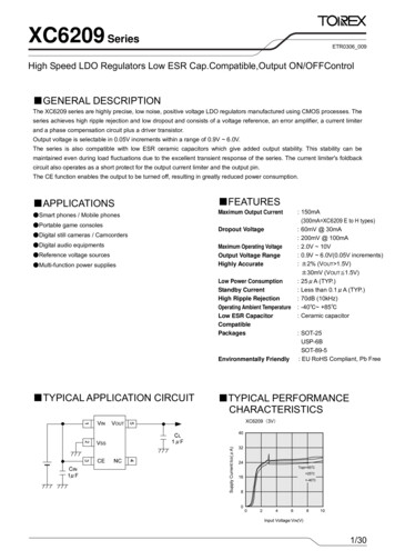
XC6209 Series TYPICAL PERFORMANCE CHARACTERISTICS (Continued)(10) Ripple Rejection RateXC6209B/F302VIN 4VDC 1Vp-pAC, IOUT 30mA, CL 1μF (ceramic)22/30XC6209B/F122VIN 2.5VDC 1Vp-pAC, IOUT 30mA, CL 1μF (ceramic)
(1.8)(0.4)(0.4)1.5 0.1(0.1)0.8 MIN4.35 MAX2.5 0.10.2MIN0.8 MIN 0.21.6-0.12.8 0.2 SOT-25 (unit:mm)(0.3) USP-6B (unit:mm)1.3MAX1.1 0.1XC6209Series PACKAGING INFORMATION SOT-89-5 (unit:mm)23/30
XC6209 Series PACKAGING INFORMATION (Continued) USP-6B Reference Pattern Layout (unit:mm)24/30 USP-6B Reference Metal Mask Design (unit:mm)
XC6209Series SOT-25 Power DissipationPower dissipation data for the SOT-25 is shown in this page.The value of power dissipation varies with the mount board conditions.Please use this data as the reference data taken in the following condition.1. Measurement ConditionCondition:Mount on a boardAmbient:Natural convectionSoldering:Lead (Pb) freeCopper (Cu) traces occupy 50% of the board areaIn top and back faces40.028.9Dimensions 40 40mm (1600mm2 in one side)Board:Package heat-sink is tied to the copper traces(Board of SOT-26 is used)Glass Epoxy (FR-4)Thickness:1.6mmThrough-hole:4 x 0.8 Diameter2.5Material:Evaluation Board (unit: mm)2. Power Dissipation vs. Ambient TemperatureBoard Mount (Tjmax 125 )Ambient Temperature( )Power Dissipation Pd (mW)2560085240Thermal Resistance ( /W)166.67許容損失Pd(mWPower Dissipation: Pd (mW)Pd vs.Ta 105周囲温度Ta( AmbientTemperature: )Ta ( )12525/30
XC6209 Series SOT-89-5 Power DissipationPower dissipation data for the SOT-89-5 is shown in this page.The value of power dissipation varies with the mount board conditions.Please use this data as the reference data taken in the following condition.1. Measurement ConditionCondition:Mount on a boardAmbient:Natural convectionSoldering:Lead (Pb) freeBoard:Dimensions 40 x 40 mm (1600 mm2 in one side)Copper (Cu) traces occupy 50% of the board areaてIn top and back facesPackage heat-sink is tied to the copper tracesMaterial:Glass Epoxy (FR-4)Thickness:1.6 mmThrough-hole:5 x 0.8 DiameterEvaluation Board (unit: mm)2. Power Dissipation vs. Ambient TemperatureBoard Mount (Tjmax 125 )Ambient Temperature ( )Power Dissipation Pd (mW)25130085520Thermal Resistance ( /W)76.92許容損失Pd(mW)Power Dissipation: Pd (mW)Pd vs. 6/30456585周囲温度Ta( )Ambient Temperature: Ta ( )105125
XC6209Series USP-6B Power DissipationPower dissipation data for the USP-6B is shown in this page.The value of power dissipation varies with the mount board conditions.Please use this data as the reference data taken in the following condition.1. Measurement ConditionCondition:Mount on a boardAmbient:Natural convectionSoldering:Lead (Pb) freeBoard:Dimensions 40 40mm (1600mm2 in one side)Copper (Cu) traces occupy 50% of the board areaIn top and back facesPackage heat-sink is tied to the copper tracesMaterial:Glass Epoxy (FR-4)Thickness:1.6mmThrough-hole:4 x 0.8 DiameterEvaluation Board (unit: mm)2. Power Dissipation vs. Ambient TemperatureBoard Mount (Tjmax 125 )Ambient Temperature ( )Power Dissipation Pd (mW)25100085400Thermal Resistance ( /W)100.00PowerDissipation: Pd (mW)許容損失Pd(mW)Pd vs. 5105周囲温度Ta( )AmbientTemperature: Ta ( )12527/30
XC6209 Series MARKING RULE SOT-25 & SOT-89-55①14②① represents product seriesMARKPRODUCT SERIES9XC6209xxxxxx③ ④23② represents type of regulatorMARKVOUT 0.1V INCREMENTSVOUT 0.05V INCREMENTSPRODUCT SERIESVOLTAGE 0.1 3.0VVOLTAGE 3.1 6.0VVOLTAGE 0.15 3.05VVOLTAGE 3.15 xYCHNXC6209GxxxxxZDKPXC6209Hxxxxx③ represents integer of the output voltageMARK0123456789ABCDEOUTPUT VOLTAGE 4.454.55MARKFHKLMNPRSTUVXYZ④ represents production lot number0 to 9, A to Z reversed character of 0 to 9 and A to Z repeated(G, I, J, O, Q, W excluded)28/30OUTPUT VOLTAGE 55.855.95-
XC6209Series MARKING RULE (Continued) USP-6B①,② represents product seriesMARK①②09PRODUCT SERIESXC6209AxxxDxUSP-6B(TOP VIEW)③ represents type of regulatorMARKTYPEPRODUCT SERIESACE pin, Active High pull-down resistor built inXC6209AxxxDxBCE pin, Active High no pull-down resistor built inXC6209BxxxDxCCE pin, Active Low pull-up resistor built inXC6209CxxxDxDCE pin, Active Low no pull-up resistor built inXC6209DxxxDx④ represents integer of output voltageMARKVOLTAGE (V)PRODUCT SERIES33.XXC6209x3xxDx55.XXC6209x5xxDx⑤ represents decimal number of output voltageMARKVOLTAGE (V) PRODUCT SERIESMARKVOLTAGE (V)PRODUCT XC6209xx7ADxXC6209xx8ADxXC6209xx9ADx⑥ Represents production lot number0 to 9, A to Z repeated (G, I, J, O, Q, W excluded)Note: No character inversion used.29/30
XC6209 Series1. The products and product specifications contained herein are subject to change withoutnotice to improve performance characteristics.Consult us, or our representativesbefore use, to confirm that the information in this datasheet is up to date.2. We assume no responsibility for any infringement of patents, patent rights, or otherrights arising from the use of any information and circuitry in this datasheet.3. Please ensure suitable shipping controls (including fail-safe designs and agingprotection) are in force for equipment employing products listed in this datasheet.4. The products in this datasheet are not developed, designed, or approved for use withsuch equipment whose failure of malfunction can be reasonably expected to directlyendanger the life of, or cause significant injury to, the user.(e.g. Atomic energy; aerospace; transport; combustion and associated safetyequipment thereof.)5. Please use the products listed in this datasheet within the specified ranges.Should you wish to use the products under conditions exceeding the specifications,please consult us or our representatives.6. We assume no responsibility for damage or loss due to abnormal use.7. All rights reserved. No part of this datasheet may be copied or reproduced without theprior permission of TOREX SEMICONDUCTOR LTD.30/30
6/30 XC6209 Series XC6209 (Type A, B) PARAMETER SYMBOL CONDITIONS MIN. TYP. MAX. UNITS CIRCUIT Output Voltage (2%)(*5) VOUT(E) (*3) IOUT 30mA VOUT(T) (*2) 0.98 V OUT (T) (*2) VOUT(T) (*2) 1.02 V ① Output Voltage (1%)(*6) VOUT(T) (*2) 0.99 VOUT(T) (*2) 1.01 Maximum Output Current IOUTMAX - 150 - - mA ① Load Regulation VOUT 1mA IOUT 100mA - 15 50 mV ①