Transcription
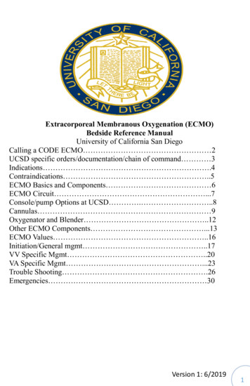
2016EXTRA CORPOREAL OXYGENATION (ECMO)LEARNING PACKAGEPaula Nekic, CNE Liverpool ICU SWSLHDSSWAHSFebruary 2016
Liverpool HospitalIntensive Care: Learning PackagesECMO Learning PackageIntensive Care UnitCONTENTSAnatomy3ECMO Definition5Indications / Contraindications6ECMO Equipment7Cannulation12Types of ECMO14CVVHDF with ECMO18Management19Nursing management22Complications / Troubleshooting26Weaning from ECMO33Learning Activities34Reference List35LH ICU2016 Learning Package ECMO Learning Package2 Page
Liverpool HospitalIntensive Care: Learning PackagesECMO Learning PackageIntensive Care UnitANATOMY5,8 Superior vena cava Carries deoxygenated blood from the veins from the upper body then intoright atrium Inferior vena cava Carries deoxygenated blood from the lower body to right atrium Aorta Carries oxygenated blood from the Left ventricle to the organs Pulmonary artery Carries deoxygenated blood from the Right ventricle to the lungsLH ICU2016 Learning Package ECMO Learning Package3 Page
Liverpool HospitalIntensive Care: Learning PackagesECMO Learning PackageIntensive Care UnitPrinciple veins and arteries Veins carry blood to heart Arteries carry blood away from heart to lungs to be oxygenatedLH ICU2016 Learning Package ECMO Learning Package4 Page
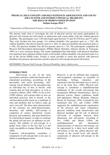
Liverpool HospitalIntensive Care: Learning PackagesECMO Learning PackageIntensive Care UnitEXTRA CORPOREAL MEMBRANE OXYGENATION (ECMO)Definition:1,7ECMO is a form of extracorpeal life support where an external artificial circulator carriesvenous blood from the patient to a gas exchange device (oxygenator) where blood becomesenriched with oxygen and has carbon dioxide removed. This blood then re-enters thepatient’s circulation.Circuit flow is achieved using a pump either centrifugal or a roller pump.ECMO evolved from cardiopulmonary by-pass.Patients who are hypoxaemic despite maximal conventional ventilatory support, who havesignificant ventilator-induced lung injury or who are in cardiogenic shock may be consideredfor ECMO support. For respiratory failure, the basic premise is that ECMO will allow the levelof ventilatory support to be reduced, which may allow time for recovery from the underlyingpathology and recovery from ventilator-induced lung injury to occur.There are two types of ECMO, veno-venous and veno- arterial.Figure 1: ECMO CircuitLH ICU2016 Learning Package ECMO Learning Package5 Page
Liverpool HospitalIntensive Care: Learning PackagesECMO Learning PackageIntensive Care UnitINDICATIONS1,2,7ECMO is indicated for potentially reversible, life-threatening forms of respiratory and / orcardiac failure, which are unresponsive to conventional therapy and it, is always applied atthe discretion of the managing intensivist or cardiac surgeon. Respiratory failure ALI/ARDS Aspiration Pneumonia Asthma Post lung transplant Lung contusion Cardiac Failure Post cardiac arrest Pulmonary embolus Drug overdose Post cardiac surgery Bridge to transplant Post heart transplant Cardiogenic shockCONTRAINDICATIONS1,2,7Absolute Contraindications Severe irreversible neurological condition Encephalopathy Cirrhosis with ascites History of variceal bleeding Moderate-severe chronic lung disease Terminal malignancy HIVAbsolute Contraindications to Veno-Venous ECMO Severe left ventricular failure EF 25% Cardiac arrestAbsolute Contraindications to Veno-Arterial ECMO Aortic dissection Severe aortic regurgitationRelative Contraindications1,2,7 Age 65 Multiple trauma with uncontrolled haemorrhage Multi-organ failureRelative Contraindication to Veno-Venous ECMO High pressure / high FiO2 IPPV for 1 weekRelative Contraindication to Veno-Arterial ECMO Severe peripheral vascular diseaseLH ICU2016 Learning Package ECMO Learning Package6 Page
Liverpool HospitalIntensive Care: Learning PackagesECMO Learning PackageIntensive Care UnitECMO EQUIPMENT1,2Perfusion Services are responsible for providing an ECMO pump and a primed circuit whenECMO is initiated in the ICU. They should be contacted as early as possible after thedecision to commence ECMO is made. In and out of hours, the cardiothoracic team on call isbrought in to establish ECMO (including the medical perfusionist), details of the on-call staffare kept in ICU, and with the hospital switchboard. A spare ECMO circuit for exchange in theevent of pump failure is available in the theatre pump room. Circuit priming and preparation are performed exclusively by Perfusion Services andequipment for this function is stored in Theatre. Perfusion staff provides 24 hoursemergency cover for this role.ECMO Cannulae (stored in Theatre) Arterial Kits 50cm Medtronic Biomedicus cannulae: sizes: 19 and 21F Venous Kits 150 cm Medtronic Biomedicus cannulae: sizes: 19, 23 and 27ECMO: initial set-up items: Centrifugal pump module Hand crank Brackets for Rotaflow oxygenator / pumpECMO pack 1x 1L crystalloid 2x tubing clampsFurther items that should remain with the patient: Spare ECMO circuit2x single transducer kits (Rotaflow)ECMO operating notes, trouble-shooting guide and observation chartRota-flow / Cardiohelp manual4 sterile tubing clampsSterile heavy scissorsHeparin-bonded 3/8 –3/8 connectorsSilicon paste (for Rotaflow flow probe)ACT machine and tubesHeater-coolerCable ties and gun30cm monitoring extension lines for use with CVVHDLH ICU2016 Learning Package ECMO Learning Package7 Page
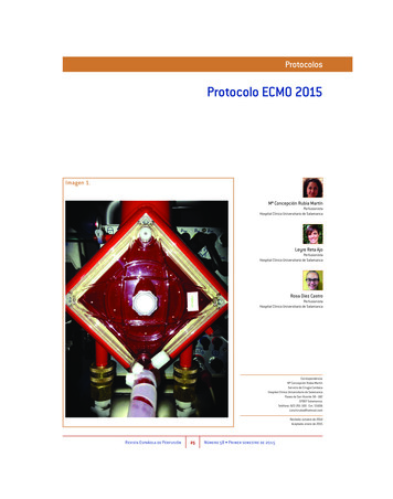
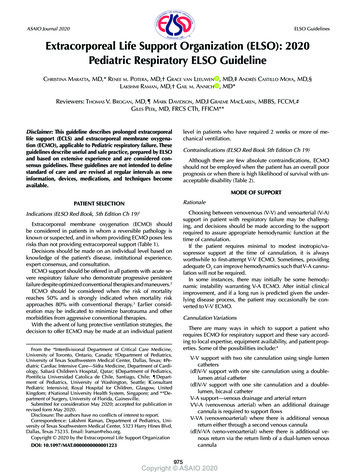
Liverpool HospitalIntensive Care: Learning PackagesECMO Learning PackageSWEEP GAS & OXYGENATORIntensive Care UnitCENTIFUGAL PUMP & SENSOROXYGENATOR &HEATER / COOLERHAND CRANKFigure 2: ECMO EquipmentOxygenatorThe oxygenator has a semi permeable membraneBlood flows across one side while a “sweep” gas 100% O2 moves in oppositedirectionThe higher the gas flow rate the more CO2 is removed Sensor Measures the flowNeeds cream applied to function. Wrap in cling –wrapLH ICU2016 Learning Package ECMO Learning Package8 Page
Liverpool HospitalIntensive Care: Learning PackagesECMO Learning PackageIntensive Care UnitCentrifugal Pump The circuit flow is achieved using a pump: either centrifugal or a roller Centrifugal is used for ECMO at Liverpool The centrifugal pump has a priming volume of 32mls which reduces haemodilutionFigure 3: Centrifugal pumpRotaflow drive The drive is what the pump sits in and the blood flow is measured in the pump outlet byultrasonic sensorThe sensor requires regular placement of cream to maintain functionCream applied hereFigure 4:Rotaflow driveRotaflow emergency hand crankRotaflow emergency hand crank This is utilised when there is a pump failure There is an LED display of the pump speed on the side of the driveLH ICU2016 Learning Package ECMO Learning Package9 Page
Liverpool HospitalIntensive Care: Learning PackagesECMO Learning PackageIntensive Care UnitPump Console Provides the controls for pump blood flow rate and speedBattery backup of 90 minutesIt can be incorporated into the bypass machine or stand alone modeBlood flow rate: LPMPump speed: RPMDial for controlling pump speedModesAlarm SilencePowerFigure 5: Pump consoleHeater / Cooler Machine A heater cooler machine is attached to oxygenator to regulate patient temperatureAim to maintain normothermiaFigure 6: Heater/coolerLH ICU2016 Learning Package ECMO Learning Package10 P a g e
Liverpool HospitalIntensive Care: Learning PackagesECMO Learning PackageIntensive Care UnitPressure Monitoring1,2Inflow and outflow pressures from the oxygenator reflect the performance of the oxygenatorThe pre-membrane pressure is at a connector near the venous inlet of the oxygenatorThe post membrane pressure is measured at the connector on the oxygenator’s arterialoutletThese pressures are displayed on a separate monitor with the ECMO circuitPre and postmembranepressuresFigure 7: Pressure MonitoringThe difference between the pre and post membrane pressure gives you the transmembrane pressure gradient.The trans-membrane pressure gradient should be less than 50mmHgAn increase in the trans-membrane pressure gradient may indicate clot formation within theoxygenatorA steadily increasing trans-membrane pressure without a concomitant increase in the circuitflows may indicate that the oxygenator needs to be replacedPre membranepressure outletPost membranepressure outletFigure 8: Pressure monitoring points post oxygenatorLH ICU2016 Learning Package ECMO Learning Package11 P a g e
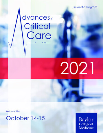
Liverpool HospitalIntensive Care: Learning PackagesECMO Learning PackageIntensive Care UnitCANNULATION4,6,7There are three ways of accessing the major vessels for ECMO: Surgical central cannulation Surgical peripheral cannulation Percutaneous cannulationSites Venous cannulation sites include the internal jugular veins, femoral veins and the rightatrium.Arterial cannulation sites are the carotid arteries, femoral arteries and the aorta.SizesRange in size from 16F -23FAnti-coagulate patient prior to insertionPercutaneous preferable to cut down to minimise bleedingTOE utilised to confirm correct placement in IVCFigure 9: ECMO CannulaePositioning of CannulaeV-V ECMOAccess cannula: For femoral insertion, use TOE (Trans Oesophageal ECHO) to confirm that the wire is inthe IVC, position the cannula tip in the IVC below the level of the diaphragm; ( 35-40 cmin an adult); Use the Avalon introducer kit to dilate the vessel to about 1 size below the cannulagauge; the tips of the femoral return and access lines should be separated by about 10cmto avoid recirculation If high flow rates are required, a second access line is inserted in the SVC, via the rightinternal jugular vein; use ultrasound to assess the diameter of the IJV and to confirm thatthe wire is in the IJV and SVC; insert the cannula 15 cmReturn cannula: Use TOE to confirm that the wire is in the IVC and to position the cannula tip at theIVC/RA junctionAvalon cannula: Maximum flow from the largest (31F) catheter is 5 Lpm Consider for any patient up to 90 kg Ensure that the right IJV is patentLH ICU2016 Learning Package ECMO Learning Package12 P a g e
Liverpool Hospital Intensive Care: Learning PackagesECMO Learning PackageIntensive Care UnitUse the Avalon introducer kit, during serial dilation of the vein and duringfinal cannula placementWith TOE or TTE (Trans Thoracic ECHO), ensure that the guidewire remains well insidethe IVC at all times, to minimise the risk of cardiac perforationThe final position of the cannula should be at least 3cm into the IVCensure that the return jet is directed towards the tricuspid valve beforesecuring the cannula to the patient’s neckFigure 10: The Avalon Elite Multi-Port Venous Femoral CatheterV-A ECMOAccess cannula: Femoral insertion, use TOE to confirm that the wire is in the IVC and to position thecannula tip in the RAReturn cannula: The arterial (short) cannula should be fully inserted to the length of the cannulaBackflow cannula: Used to prevent ischemia occurring distally to the arterial cannulation site in peripheral VA ECMO Inserted in the artery distal to the ECMO cannulation site Connected to the luer connector on the arterial cannula by a piece of extension tubing Should be inserted and connected at the time of cannulation, or as soon as practical later After arrival in ICU, the ultrasonic flow probe should be used to confirm that there is flowin the extension tubingAccess Cannula(Venous)Return Cannula(Arterial)Tubing to backflowcannulaDoppler examination of the blood flow in the back-flow cannula is indicated if deterioratingleg perfusion is observed in the cannulated leg.LH ICU2016 Learning Package ECMO Learning Package13 P a g e
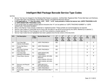
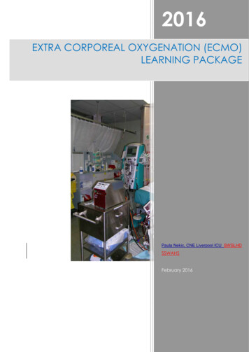
Liverpool HospitalIntensive Care: Learning PackagesECMO Learning PackageIntensive Care UnitTYPES OF ECMO4,6,7There are two basic types which are described by the site of drainage & where the bloodreturnsVeno-venous Deoxygenated blood is drained from venous circulation into the ECMO circuit Blood is oxygenated via the oxygenator and is returned to the right atrium Drains from major vein & returns to a major vein Supports only the lungs Adequate circulation is provided by the native cardiac outputVeno-arterial Deoxygenated blood is drained from venous circulation into the ECMO circuit Passes through the oxygenator and is returned directly to the arterialcirculation Drains from major vein & returns to major artery Supports heart & lungsFigure 11: ECMO CircuitVENO VENOUS ECMOInvolves venous blood from the patient being accessed from the large central veins (via the“access line”) and returned to the venous system near the right atrium (via the “return line”)after it has passed through an oxygenator.It provides support for severe respiratory failure when no major cardiac dysfunction exists.When flow through a single access cannula is insufficient to support the high ECMO flowrate that may be required in severe respiratory failure, a second venous access cannula maybe required.V–V ECMO improves the patient’s oxygenation by reducing the amount of blood that passesthrough the lung without being oxygenated and in addition removes CO2 from the patient’sblood.This allows the level of ventilatory support to be reduced, which reduces ventilator-inducedlung injury.LH ICU2016 Learning Package ECMO Learning Package14 P a g e
Liverpool HospitalIntensive Care: Learning PackagesECMO Learning PackageIntensive Care UnitThe efficiency of oxygenation by the ECMO circuit depends on the pump flow relative to thepatient’s cardiac output.The patient’s oxygenation should increase with increasing ECMO flow rate, if this does notoccur, recirculation of blood between the inflow and outflow cannulae should be suspectedSecond access cannula :using SVCAccess cannula: using IVCReturn cannulaFigure 12: An example of Veno-venous ECMOV-V ECMO and CO2:V-V ECMO is more efficient at removing CO2 from the blood than delivering oxygen.The amount of CO2 removal depends on the ECMO flow rate relative to the patient’s cardiacoutput and also depends on the oxygen flow rate (sweep gas) to the oxygenator.Increasing oxygen flow rate decreases the CO2 in the blood leaving the oxygenator(analogous to the effect that increasing minute ventilation has on arterial PCO2)The oxygen flow rate (the sweep flow) to the oxygenator should be roughly twice the ECMOflow rate. Eg: if the ECMO Flow rate is 3L, the oxygen flow rate shoud be 6L. With an ECMOflow rate of approximately 2/3 the patient’s cardiac output, and an oxygen flow rate of twicethe pump flow, nearly all of the patient’s CO2 production can be removed by the oxygenator.V-V ECMO and O2:Arterial O2 is determined by the relationship between the ECMO pump flow and the patientscardiac outputIf the ECMO pump flow is low compared to patients cardiac output the arterial O2 will also belowIncreasing the ECMO pump flow will increase the O2 in the mixed venous circulation &therefore increase the arterial O2LH ICU2016 Learning Package ECMO Learning Package15 P a g e
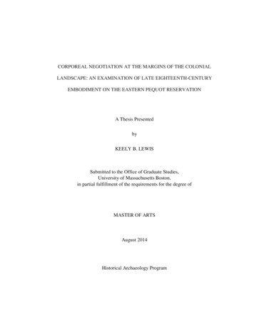
Liverpool HospitalIntensive Care: Learning PackagesECMO Learning PackageIntensive Care UnitProviding ECMO pump flows equal to 66% of the patients cardiac output will achieve asaturation of 90% (Locker et al., 2003)Common for patients on V-V ECMO to have PO2 in range of 55-90mmHgIn Summary To remove CO2 increase the O2 sweep gas To increase the p02 you increase the pump flowVENO-ARTERIAL ECMOInvolves venous blood from the patient being accessed from the large central veins andreturned to a major artery after it has passed through the oxygenator.It provides support for severe cardiac failure, (usually with associated respiratory failure),most commonly after cardiac surgeryAccess cannulaReturn cannulaFigure 13: An example of Veno – Arterial ECMOMay be used at low rates (2-3L/min) to provide partial assistance or at high rate of 4-6L/minto totally replace the patients cardiac outputAll gas exchange is delivered directly to arterial circulation so PO2 levels 400-500mmHg canbe achievedChanging flow rates will not affect arterial PO2 but will determine the patients cardiac outputECMO circuit malfunctions will result in cardiac arrest as the ECMO flow rate is the patientscardiac outputV-A ECMO may be applied via central or peripheral cannulationIf peripheral cannulation is applied any residual native cardiac output passes through thelungs. If the lungs are affected by disease or mechanical ventilation is insufficient the bloodof the residual cardiac output will remain hypoxic as it enters the systemic circulationLH ICU2016 Learning Package ECMO Learning Package16 P a g e
Liverpool HospitalIntensive Care: Learning PackagesECMO Learning PackageIntensive Care UnitAnatomically there is potential for this hypoxic blood will be delivered to the head, neck andright arm.Therefore any patient on peripheral V-A ECMO should have O2 saturations measured on theforehead or right handPatients on V-A ECMO require adequate ventilation with FiO2 of at least 50%to reduce therisk of coronary and cerebral hypoxiaCarbon dioxide removal is controlled by the sweep gas flow rates as in V-V ECMO, but ifthere is some native cardiac output and the lungs are ventilated normally some CO2 will beremoved by the lungsV-V AND V-A ECMOV-VV-A Provides respiratory support Blood from and returned tovenous circulationProvides complete respiratory& hemodynamic support Blood from venous circulationthen returned to arterialcirculation Less arterial injury Decreased likelihood air orclot emboli from the circuit Bridge to recovery or for hearttransplant Low pressure circuit thereforeimproving longevity of circuit Decreased hemodynamicinstability as blood is returnedand withdrawn from samesidePump flow is the pt CO, anydisruption to flow cardiacarrest All gas exchange inoxygenator is delivered toarterial circulation arterialp02 400-500mmHg Changing flow rates affectscardiac output Achieves arterial p02 5590mmHg Changing flow rates affectsp02 Increasing O2 sweep gasremoves more CO2LH ICU2016 Learning Package ECMO Learning Package17 P a g e
Liverpool HospitalIntensive Care: Learning PackagesECMO Learning PackageIntensive Care UnitCONNECTING CVVHDF TO ECMOThe Prismaflex machine can be connected to the ECMO circuit. This should be done by theperfusionist. Once the ICU nurse has been trained in this procedure it may be done by thenurse. If the ICU nurse is unsure on how to make the connections the perfusionist must becalled. The ECMO circuit is a high pressure circuit and opening taps and connections willresult in air entering system or blood spills.The access and return lines of the dialysis machine are attached to the ECMO circuit to thetwo three-way taps between the outlet of the pump head and the oxygenator.ACCESS: Access line goes to the three way tap closet to the centrifugal pump If pressure within ECMO circuit causes high pressure alarm in Prismaflex change accesspressure alarm in set up to positive. Always should select positive ACCESS Pressure forECMO and CRRT. Centrifugal pumpCRRTAccess lineFigure 14: Access Line for CRRT connection to ECMO CircuitRETURN: Return line is connected to three way tap closest to the oxygenator 3 way taps not to be flushed with any solution including sodium chloride Betadine to wipe connections when disconnecting from ECMOOxygenatorReturn lineFigure 15: Return Line for CRRT connection to ECMO CircuitLH ICU2016 Learning Package ECMO Learning Package18 P a g e
Liverpool HospitalIntensive Care: Learning PackagesECMO Learning PackageIntensive Care UnitMANAGEMENT1,4,6,7Commencement of ECMO: Check ACT and ensure 200 seconds Ensure oxygen line is connected to oxygenator. Gas flow should be commenced at a rateequal to or greater than the anticipated circuit blood flow (usually 5-6L/min) Clean loop is opened and handed to the cannulating physician The circuit is cut between two clamps allowing sufficient length on the access line andreturn line to prevent any tension on the circuit. Note the pump trolley is best kept at the“feet” end of the patient’s bed (picture) Circuit is connected to cannulae ensuring no air is introduced Clamps removed as circuit flows are gradually increased Target flow rates are determined by the cannulating Physician For V-V ECMO target flows must provide adequate arterial oxygenation For V-A ECMO target flows must provide adequate oxygen delivery Check patient and circuit arterial blood gases Reduce ventilator settings as indicated Establish baseline anticoagulation sampling times.Securing Access and Return Lines Once the cannulae position has been confirmed femoral lines should be secured bysuturing to patients leg and then using large opsite over the top of the cannulas. Theinternal jugular line is best stabilised by directing the tubing around the head beforepassage down the body to the oxygenator. The loop around the head is immobilised bystrapping around the patient’s foreheadFigure 16: Securing ECMO LinesCare of Equipment: Ensure AC power alarm is turned on when using wall powerKeep pump head in a position to minimise risk of accidental contact with other equipmente.g. X-ray machineEnsure heater cooler hoses & O2 flow tubing is not obstructed by feet, bed etcDon’t allow any part of the circuit to come in contact with alcohol or organic solventsLH ICU2016 Learning Package ECMO Learning Package19 P a g e
Liverpool HospitalIntensive Care: Learning PackagesECMO Learning PackageIntensive Care UnitMedical Staffing:There is a medical perfusionist (a cardiac anaesthetist) and a pump technician available 24hours for: Initiation of ECMO Priming of circuits ECMO circuit maintenance and nursing supportOut of hours (1800 to 0800 weekdays and weekends), the medical perfusionist may becontacted directly or via switchboard.Their contact details should be left at the patient’s bedside.They should be contacted about all circuit and patient issues related to ECMO.The ICU consultant is responsible for all medical decisions involving ECMO while the patientis in ICU and must also be notified of any changes. They can be contacted 24 hours.Respiratory ManagementOnce adequate ECMO flows have been established and the patient’s oxygenation hasimproved, the level of ventilatory support is reduced.Typical ventilatory goals would be: FiO2 0.7, PIP 35cmH2O, PEEP 15cmH2O respiratory rate 10bpm (V-A)Pump Flow rates: Flow rates: V-V 2/3 of pts cardiac output, minimum 50% of patient’s cardiac output O2 flow rate twice ECMO flow rate Avoid increasing fluids to maintain pump flow as this may decreaserespiratory function Lowest SaO2 85-90% or PaO2 of 55-60Flow rates V-A Flow rate 2.1- 2.4l/min/m2ECMO flows less than 2litres for long periods should be avoided to prevent clots in circuitFigure 17: Pump flow ratesLH ICU2016 Learning Package ECMO Learning Package20 P a g e
Liverpool HospitalIntensive Care: Learning PackagesECMO Learning PackageIntensive Care UnitLine pressures: Pre-membrane pressure 300mmHgTrans membrane gradient normal 50mmHg if 150mmhg consider circuit changeTemperature: Normothermia, set heater cooler at 37degrees The heater-cooler settings should only be altered by the perfusion staff unless the nursehas been trained to do this. Should the patient become unexpectedly hypo- orhyperthermic while on ECMO, the medical perfusionist on call must be contactedimmediately.Anticoagulation:Although the ECMO circuit has an anticoagulant lining, low-dose heparin is usuallyadministered to prevent clot formation The ACT is usually used to titrate heparin infusion rate in the first 24 hours and ismeasured 6 hourly over the first day. It is performed by the attending nurse, using 2 mlsof arterial or venous blood. A usual target for ACT in the non-bleeding patient with platelet count 80,000 is 140–160. Beyond 24 hours, the APTT performed in the Haematology lab is primarily used to guideheparin therapy. It is performed 4 times per day and is routinely labelled as urgent toensure safe response times. A usual target for APTT in the non -bleeding patient with platelet count 80,000 is 4555sec.Investigations required for patients on ECMO include: Daily CXRDaily bloods: FBE; Urea, Creatinine, Electrolytes; Mg; PO4; LFTClotting: APTT, INR, Fibrinogen are performed daily (morning bloods)APTT is performed 6 hourly as determined by the ICU consultant while the patient is onECMO.Plasma free Hb is performed when clinically indicated. The safe range for this is 0.1g/L.Levels above this MUST be discussed with ICU Consultant and medical perfusionist.Daily d-Dimers should be preformedBlood cultures 3 times per week or as indicated. Unlike other patients, these samplesshould be taken from the circuit or through existing lines. Do NOT perform venipuncturefor the collection of blood cultures. (Samples from circuit are obtained by a perfusionist)Other cultures as indicatedFigure 18: ECMO Cannula on X-rayLH ICU2016 Learning Package ECMO Learning Package21 P a g e
Liverpool HospitalIntensive Care: Learning PackagesECMO Learning PackageIntensive Care UnitGeneral management Doppler examination of the blood flow in the back-flow cannula is indicated if deterioratingleg perfusion is observed in the cannulated leg. Antibiotics (IV vancomycin) to prevent line sepsis are commenced at the start of ECMO.Other antibiotics are prescribed as indicated. Stress ulcer prophylaxis is standard. No procedure can be performed on a patient on ECMO without the consent of the ICUconsultant. Protamine is contraindicated for patients on ECMO as it can cause serious circuit relatedthrombosis All changes to circuit flows, gas and blood, should be relayed to the medical perfusionistvia ICU Senior Registrar All changes to circuit anticoagulation should be relayed to the medical perfusionist viaICU Senior RegistrarNursing Management1,4,6,7Nursing responsibilities are to patient care. Responsibility for technical maintenance of theECMO circuit lies with the medical and technical perfusionists Liverpool Hospital.Patient positioning and the safe performance of pressure area care are affected byECMO support. Patients with ECMO support with an “open sternum” may not be rolled and requirealternate means of preventing pressure area care eg: KCI mattress. Daily chest x-raysand other patient moves require a Jordan Frame and the presence of medical staff and/orperfusionist to ensure no change in circuit flow result as a consequence of movement. Other patients on ECMO support can be log-rolled and moved for chest x-rays. Thesemoves can be safely performed but require a designated staff member to ensure notension is transmitted to the cannulae and the circuit tubing is not kinked. This includespatients with surgical grafts for femoral artery access but extra care is required to preventobstruction to ECMO flow at this site. Moves are scheduled between the hours of 0800and 2000 and not during the night (unless there is an urgent patient need). All moves are to be performed with medical staff knowledgeable in ECMO, immediatelyavailable to assess any circuit changes that may occur. Patients nursed at 2:1 nursing ratioThe ECMO patient must NOT be left unattended at any time Relief for breaks should be arranged so that a suitably experienced member of staff ismonitoring the patient and ECMO circuit at all times The ECMO patient is dependent on the circuit for maintenance of oxygenation /- cardiacoutput Any disruption to ECMO flow will result in rapid deterioration, which if not rapidly rectifiedwill result in deathSafety checks ECMO plugged into blue power pointHand crank near bySecure oxygen flow to oxygenatorCheck flow settingsLH ICU2016 Learning Package ECMO Learning Package22 P a g e
Liverpool Hospital Intensive Care: Learning PackagesECMO Learning PackageIntensive Care UnitCheck Pump access line for chatteringPatient must not be left unattended at any timeHourly observationsPump flow rateECMO observation chart Nursing ECMO observation chart must be maintained andreviewed by the rostered medical perfusionist. Nursing staff can communicate anydifficulties with observations with the rostered perfusionist. This data will form part of themedical record. Haemodynamic observations Continuously monitor patient and ECMO set for drop in BP/ CVP Evidence of hypovolaemia in the form of fluctuating flow rates and ‘shaking’ of ECMOtubes Hypovolaemia (relative or absolute) may result in disrupted blood flow through thecircuit Sucking down of the access cannula against the vessel wall may occur inhypovolaemia potentially causing trauma to vessel endothelium and haemolysis Blood flow through the ECMO circuit is essential for maintenance of gaseousexchange, and also to maintaining haemodynamic stability Pre & post membrane pressure Oxygen flow to oxygenator Ensure oxygen tubing is secured to floor Check flow on oxygen outlet Patient temperature Temperature measurement should be initiated and continuously monitored throughoutECMO therapy via either blood thermister in the presence of a PiCCO/ PA catheter To promote homeostasis, normal body temperature must be maintained, unless mildhyperthermia is clinically desired Continuous monitoring allows for early detection and therefore management oftemperature changes Access & return cannula for bleeding Observe for oozing of blood, and maintain secure dressings Secure dressings are required to maintain cleanliness of cannulae sites, and also tohelp stabilise the cannulae Circulation observations lower limbs Limb temperature Limb colour Pedal pulses Capillary refill Due to the large bore cannulae distal arterial perfusion may be compromised in A-VECMO, while the venous cannulae may lead to DVT formation Input & output, haematuria Haematuria is often present when there is haemolysis, and therefore should bereported and investigated appropriately Ventilation observations should be attended: mode, Fi02, Tidal volume, respiratory rate,PEEP, pressure support, ins
Perfusion Services are responsible for providing an ECMO pump and a primed circuit when ECMO is initiated in the ICU. They should be contacted as early as possible after the