Transcription
Experiment 5:Polarization and InterferenceNate Saffoldnas2173@columbia.eduOffice Hour: Mondays, 5:30PM-6:30PM @ Pupin 1216INTRO TO EXPERIMENTAL PHYS-LAB1493/1494/2699
Introduction Outline: Review of physics:1. Electromagnetic waves2. Polarization of an EM wave3. Interference and diffraction (double and singleslit experiments)Polarization and Interference experiment:1. Description of the apparati2. Data analysisTips for the experimentPHYS 1493/1494/2699: Exp. 5 – Polarization and Interference2
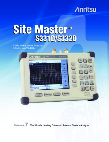
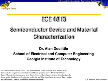
Electromagnetic waves Electromagnetic wave oscillating electric and magneticfieldsAn EM wave propagates in vacuum at the speed of lightElectric and magnetic fields are always perpendicular toeach other(James Clerk Maxwell Pretty smart guy )PHYS 1493/1494/2699: Exp. 5 – Polarization and Interference3
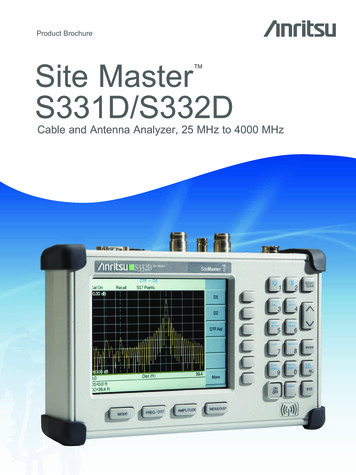
Polarization Polarization of a light wave direction of oscillation of theelectric fieldEvery day light is usuallyunpolarized. All directions of theelectric field are equally probable.Linearly polarized light thedirection of oscillation at aparticular point in space is alwaysthe sameUnpolarized beam of lightmoving perpendicularly tothe screen. No preferreddirection of oscillationLinearly polarized beam oflight moving perpendicularlyto the screen. Electric fieldpoints in one direction only.PHYS 1493/1494/2699: Exp. 5 – Polarization and Interference4
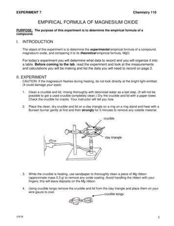
Polarization by selective absorption White light (as from a light bulb) is usually unpolarized.Polarizer material that selects one particular direction ofoscillation of the incoming lightIf we place two linear polarizers in sequence then:1. First one: it makes unpolarized light linearly polarized2. Second one: it determines which fraction of the incoming lightarrives at the end of the apparatusPolarized anddifferent intensityUnpolarizedPolarized buthalf intensityPHYS 1493/1494/2699: Exp. 5 – Polarization and Interference5
Malus’ Law If we place two polarizers in sequence, the magnitude ofthe transmitted polarized electric field will depend on theangle between polarizers.Electric field coming outof second polarizerElectric field comingout of first polarizerOrientation of secondpolarizerOrientation of firstpolarizer This is how the electric field behaves when passingthrough two linear polarizers. What do we actually see?PHYS 1493/1494/2699: Exp. 5 – Polarization and Interference6
Malus’ Law Our eyes cannot detect the electric field directly We only see its time average Intensity magnitude squared of the electric field intensityFrom the formula in the previous slide we obtain the socalled Malus’ Law:Intensity coming outof second polarizerRelative angle between the axes ofthe two polarizersIntensity coming out offirst polarizerPHYS 1493/1494/2699: Exp. 5 – Polarization and Interference7
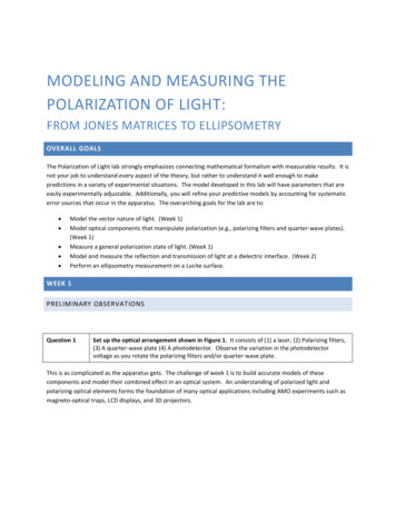
Malus’ Law The intensity coming out of the polarizers as a function ofthe angle between the two then looks like:If the two polarizers are2 perpendicular to each I o cosother no light istransmittedI I o cos2PHYS 1493/1494/2699: Exp. 5 – Polarization and Interference8
Interference An essential property of waves is the ability to getcombined with other wavesThe result of this superposition can lead to a wave withgreater or smaller amplitudeThis phenomenon is called interferenceMaxima superimposedto minimaMaxima superimposedto maximaThey cancel outThey add to eachotherPHYS 1493/1494/2699: Exp. 5 – Polarization and Interference9
Young's double slit experiment Question: if light is a wave,what should we expect fromit?Young's double-slitexperiment (1801): Pass light through two verynarrow slits and observepattern on distant screen.Waves coming out of the twoslits interfere and create afringe pattern of bright anddark spotsPHYS 1493/1494/2699: Exp. 5 – Polarization and Interference10
Young's double slit experiment The pattern on the wall can be derived from opticsWe need to see how two rays from the two slits interferewith each otherMinimacorrespond todark spotsMaximacorrespond tobright spotsPHYS 1493/1494/2699: Exp. 5 – Polarization and Interference11
Condition for a bright spot Let the screen be at adistance D from the slits. Let’stake this distance much largerthan the distance betweenslits (D d).Rays emerge almost parallelto each other.In order for both of them toend up on the same point(and hence interfere) one ofthe two must travel a slightlylonger distance:Extra distancetraveled by thesecond rayPHYS 1493/1494/2699: Exp. 5 – Polarization and Interference12
Condition for a bright spot We want a bright spot, i.e. constructive interferenceIn order for two maxima to overlap the difference in traveldistance must be a multiple of the wavelengthwhere m is an integer number and λ is the wavelength ofincoming light Since D d we can use the small angle approximation:The distance of the m-th brightspot from the center is then:PHYS 1493/1494/2699: Exp. 5 – Polarization and Interference13
Young's double-slit experiment The pattern appearing in the double slit experiment is dueto the interference effectHowever, in real life you will also have diffraction. Lightphenomena will always be a combination of the two effectsPHYS 1493/1494/2699: Exp. 5 – Polarization and Interference14
Young's double-slit experiment The pattern appearing in the double slit experiment is dueto the interference effectHowever, in real life you will also have diffraction. Lightphenomena will always be a combination of the two effectsDiffraction Spread ofwaves around an obstacle orslitOnly relevant when theobstacle size is comparableto the wavelengthWave behaves as if it wasinterfering with itselfPHYS 1493/1494/2699: Exp. 5 – Polarization and Interference15
Diffraction intensity pattern If diffraction is made around a single slit the intensity isgiven by:a single-slit widthλ wavelengthθ angle on the screenPHYS 1493/1494/2699: Exp. 5 – Polarization and Interference16
Diffraction intensity pattern If diffraction is made around a single slit the intensity isgiven by:a single-slit widthλ wavelengthθ angle on the screen Single-slit minima occur at:Again, using small angleapproximation, the minimaoccur at:PHYS 1493/1494/2699: Exp. 5 – Polarization and Interference17
Diffraction intensity pattern If diffraction is made around a single slit the intensity isgiven by:a single-slit widthλ wavelengthθ angle on the screen Single-slit minima occur at:Again, using small angleapproximation, the minimaoccur at:Careful! The expression is similar to that for thedouble slit but now it’s for dark spots, not brightonesPHYS 1493/1494/2699: Exp. 5 – Polarization and Interference18
The ExperimentPHYS 1493/1494/2699: Exp. 5 – Polarization and Interference19
Goals To study the polarization properties of EM waves Polarize a beam of white lightVerify Malus' Law: measure intensity of white light when lighttravels through two polarizers at an angle with respect to eachother:To study the interference and diffraction phenomena Use a He-Ne laser as coherent light source (single wavelength) Determineof the laser from the double-slit interference pattern Determineof the laser from single-slit diffraction patternPHYS 1493/1494/2699: Exp. 5 – Polarization and Interference20
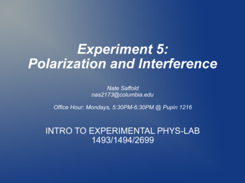
EquipmentSuper precise scientific generator ofunpolarized white light a light bulb Allows you tochange thereading point onthe screen byfractions of 1mmMeasures the(relative)intensityPHYS 1493/1494/2699: Exp. 5 – Polarization and Interference21
Part 1: Malus’ law Equipment: Incandescent light source (source of EM waves) Polarization filters Photometer (measures intensity of outgoing EM waves)For polarization: Incandescent light is a source of unpolarized EM wavesE-field has no preferred directionPlace a polarizer in front of the incandescent light source Outgoing light should bepolarized!PHYS 1493/1494/2699: Exp. 5 – Polarization and Interference22
Part 1: Malus’ Law Polarizers in sequence Place two polarizers in front of the light sourceMeasuring intensity of light: Align the axis of both polarizers such that they are parallel to eachother. Measure and record intensity.Rotate the second polarizer in 5-10 degree increments withrespect to the first one. Record intensity at each stepPHYS 1493/1494/2699: Exp. 5 – Polarization and Interference23
Part 1: Malus' Law According to Malus’ law: You will have a set of Linearize the data by plotting pairsvs.Perform a linear fitand find slope andintercept (w/ errors!).Are they what youexpect?Plot residuals tocheck forconsistency of the fitPHYS 1493/1494/2699: Exp. 5 – Polarization and Interference24
Part 2: double-slit experiment Procedure: Mount laser in far end of optical bench. Mount slit set C (double-slit) in front of the laser beam. Observe double-slit intensity pattern with a white piece of paper. Use linear translator with fiber optic attached to measureintensity at different positions in the transverse directionPHYS 1493/1494/2699: Exp. 5 – Polarization and Interference25
Part 2: double-slit experiment Record the position ofmaxima Plot xm vs. order number (m) Perform a linear fit Use slope to estimate thewavelength of the laser Remember to propagateuncertainties!If you are careful enough theresults can be fairly accurate:PHYS 1493/1494/2699: Exp. 5 – Polarization and Interference26
Part 3: single-slit envelope Once again take measurements in the transverse directionbut in smaller increments and look for brighter spotsPlot relative intensity (I/Io) vs.order number m.Should be able to observethe single-slit envelope.Using the single-slit width(a), determine wavelength oflaser.IMPORTANT: For this part of the experiment switch to slit D!PHYS 1493/1494/2699: Exp. 5 – Polarization and Interference27
Part 3: single-slit envelope Once again take measurements in the transverse directionbut in smaller increments and look for brighter spotsPlot relative intensity (I/Io) vs.position xm.Should be able to observethe single-slit envelope, notewhere the single slit minimaare xnPlot xn vs. n, where n isminima order numberUsing slope and wavelengthfrom part 2, determine aPositionNOTE: This part may vary depending onyour TA. Ask them for the exact procedure!PHYS 1493/1494/2699: Exp. 5 – Polarization and InterferenceIMPORTANT: For this part of the experiment switch to slit D!28
Tips Here are some tips that might beuseful:1. For all the three parts: be careful whenyou read the intensity. The photometer isanalogical and the reading might beinfluenced by parallax. Try to read thephotometer always in the same way2. For the polarizer part: put the polarizersas close as possible to the optic fibercable to minimize the amount ofenvironmental light coming in.3. For the last part: move everything closerto the laser to make the pattern biggerbut remember to change the value of D!PHYS 1493/1494/2699: Exp. 5 – Polarization and Interference29
3 Electromagnetic waves Electromagnetic wave oscillating electric and magnetic fields An EM wave propagates in vacuum at the speed of light Electric and magnetic fields are always perpendicular to each other (James Clerk Maxwell Pretty smart guy ) PHYS 1493/1494/2699: Exp. 5 - Polarization and Interference