Transcription
Experimental Determination of the Speed of Light by the FoucaultMethodR. Price and J. ZizkaUniversity of ArizonaThe speed of light was measured using the Foucault method of reflecting a beam oflight from a rotating mirror to a fixed mirror and back creating two separatereflected beams with an angular displacement that is related to the time that wasrequired for the light beam to travel a given distance to the fixed mirror. By takingmeasurements relating the displacement of the two light beams and the angularspeed of the rotating mirror, the speed of light was found to be (3.09 0.204)x108 m/s,which is within 2.7% of the defined value for the speed of light.1 IntroductionThe goal of the experiment was to experimentally measure the speed of light, c, in a vacuum byusing the Foucault method for measuring the speed of light. Although there are many experimentalmethods available to measure the speed of light, the underlying principle behind all methods on the simplekinematic relationship between constant velocity, distance and time given below:c Dt(1)In all forms of the experiment, the objective is to measure the time required for the light to travel a givendistance. The large magnitude of the speed of light prevents any direct measurements of the time a lightbeam going across a given distance similar to kinematic experiments. Galileo himself attempted such anexperiment by having two people hold lights across a distance. One of the experiments would put out theirlight and when the second observer saw the light cease, they would put out theirs. The first observer wouldtime how long it took for the second light to go out, giving an estimate on the speed of light. However, it wasfound that the time lapse between the two events was near instantaneous suggesting that such a methodwas not precise enough, and a more interesting result at the time, that the speed of light was much larger inmagnitude than thought1.To correct for these problems, Foucault devised a method which was able to avoid such issues byindirectly measuring the time the light traveled. Foucault’s method used a light source and rotating mirrortogether to derive the speed of light2. The Foucault method uses the light source to produce a focused beamon the rotating mirror. The light from the rotating mirror is then reflected at an angle to a fixed mirrorwhich is aligned to face perpendicular to the reflected light beam. Therefore the light is reflected directlyback to the rotating mirror where it was first reflected. During the time the light had traveled the distancebetween the two mirrors, the rotating mirror had changed its orientation to the beam of light, thus the12, Hecht, Eugene. Optics, 4th Edition. San Francisco: Addison Wesley, 2002.
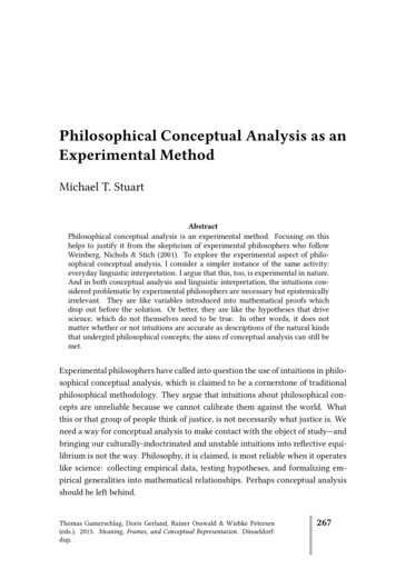
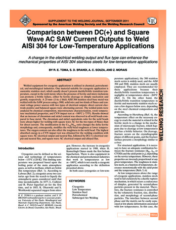
16 October 2007returning beam of light will be reflected off at a separate angle. The difference in the angle between thelight source to the rotating mirror and the rotating mirror the second reflected beam is related to the timethat was required by the light to travel the distance between the fixed and rotating mirrors. Using therelations of the experimental setup, Equation 1 was used to determine the speed of light.1.1SetupFor the experiment the methods were updated to use modern equipment to provide more accurate andprecise results. A diagram of the experimental setup is shown below in Figure 1:Figure 1 - Diagram of Experimental SetupThe experiment used a laser to provide as the light beam because it creates a focused beam of light to travelbetween all components. The rotating mirror used was a double sided plane mirror attached to a motorapparatus that allowed a variable control of the motor rotation speed. The rate of rotation was measuredusing a light sensor in conjunction with a frequency counter. As the mirror rotated with the laserpositioned on it, there was an angle of the mirror that reflected the laser light beam toward the light sensor.When the laser beam was directed at the light sensor, it created a voltage which could be then measured bya connected frequency counter.A lens with a 5 meter focal length was placed between the rotating and fixed mirrors because thelaser beam had an angular divergent property associated with the beam. Over large distances, the laserPage 2 of 9
16 October 2007beam became too dispersed to be targeted precisely onto the two mirrors. The lens focused the laser beamdirectly to a point source on both mirrors making the beams more precisely optically aligned. A beamsplitter was used in order to redirect the returning light beam onto a frosted glass plate. The frosted glassplate allowed a simplification in viewing because it disperses the incoming laser beams in all direction sothat a ‘head-on’ viewing angle with the microscope is not required. The difference between these twopoints was measured by using the measuring microscope placed in front of the frosted glass screen andrecording the value of displacement of the two beams.1.2DerivationFrom simple kinematics, the speed of light is related to the time t it takes a beam of light to travel a distanceD from Equation 1. In the experiment, the distance and time measured were for a beam of light to travelbetween the rotating and fixed mirrors and back in Figure 1. Therefore by the setup the time to travel thedistance was:t 2Dc(2)However, during the time period t, the rotating mirror is held at a fixed angular velocity of ω. Because theangular velocity is constant, then𝜔𝑚𝑖𝑟𝑟𝑜𝑟 𝜃𝑡(3)The angular dependence Δθ is also related to the return of the light beam to the beam splitter and thedisplacement Δx of the light beam on the frosted glass plate. The angle between the two laser beamsstriking the beam splitter is determined from the law of reflection:θi θr(4)For a beam of light striking a stationary mirror, the total angle between the reflected and incident lightbeams is given as:θi θr 2θi(5)Therefore for every angular change in the rotating mirror by Δθ, the incident angle of the laser beamstriking it changes by Δθ and the new incident angle becomes θi Δθ. The increase in the angle results inthe total angle increasing as 2θi 2Δθ, thus the total distance between the two light beams striking thebeam splitter is given by a change of 2Δθ. By the relationships from the geometry in the two return pathsand from small angle approximations the displacement and angle are related by:Tan 2Δθ 2Δθ θ x2rΔxr(6)Therefore by relating Equations 3 and 6 for the angle based on time and the displacement on the glassscreen together yields the relationship:Page 3 of 9
16 October 2007ωmirror θ x t2rtHowever, the time of rotation can be related to the time traveled by the light: xt 2rωmirror(7)(8)Equation 2 and Equation 8 can be related so that:2D x c2rωmirror4rdωmirrorc x(9)(10)Within the experiment, it is important to know c in terms of the frequency instead of angular frequencybecause the frequency counter used returns the measurement in units of Hertz. Therefore by definition,ωmirror 2πfmirror(11)Then by substituting Equation 11 into 10:c 8πrdfmirror x(12)Another correction is required for the experiment in terms of frequency. The frequency measured on thefrequency counter is twice that of the rotation frequency because the mirror rotated is doubled sided sothen the laser beam is reflected into the light sensor twice per each rotation of the mirror. Therefore,1fmirror fmeasured2(13)Substituting Equation 13 into Equation 12 results in:c 4πrdfmeasured x(14)Because the experiment is performed within air and not a vacuum, the result from Equation 14 abovewould give c within air. Therefore by multiplying by the index of refraction of air, we get c within a vacuum:c 4πrdfnair x(15)Where: 3r is path from the rotating mirror to the beam splitter to the frosted screenD is the distance between the fixed mirror and the rotating mirrornair is the index of refraction for air, given as 1.00029263f is the frequency as given by the frequency counter used within the experimental setupHecht, Eugene. Optics, 4th Edition. San Francisco: Addison Wesley, 2002.Page 4 of 9
16 October 2007 x is the displacement of the laser beam across the frosted glass screen2 Experimental MethodsFrom Equation 15, the objective of the experimental measurements was to gain the relationship betweenthe two observable, alterable quantities: the frequency of the mirror rotation and the observation of thelaser beam displacement across the frosted glass plate. By rearranging Equation 15, a more usefulrelationship can be obtained:𝑥 4𝜋𝑟𝑑𝑛𝑎𝑖𝑟𝑓𝑐(16)Equation 16 reveals a linear relation between the displacement on the glass screen and the frequency of themirror. Therefore the method of collecting data to find the speed of light was to take data points relatingthe frequency and displacements and to perform a least-square fit in order to determine experimentalvalue of the relationship and compare it to the known value.To setup the experiment, the optical systems involved had to be aligned in order to create the beam pathdisplayed in Figure 1. First, the laser was aimed at the rotating mirror and slowly adjusted so that the laserbeam was directed toward the center of the mirror. Next the rotating mirror was slowly aimed at the centerof the fixed mirror. Next the lens was placed between the fixed and rotating mirrors in order to focus thereturn beam from the fixed mirror to the rotating mirror as otherwise the angular dispersion of the laserbeam created difficulty in detecting where the return beam was directed to. The fixed mirror was verycarefully adjusted so that the return path through the lens reflected back onto exactly the same location onthe rotating mirror where the first reflection occurred. With all the optics aligned, the beam appeared onthe frosted glass screen as a point. The setup was then tested by covering the lens between the mirrors.When this was performed, the beam on the glass plate disappeared, verifying the beam was being reflectedfrom the fixed mirror. Next, the position of the light beam on the frosted glass plate with no rotation wasrecorded by using the measuring microscope by aligning the crosshair of the microscope to the center ofthe laser beam as it appeared within the scope.To measure the mirror rotation frequency, the light sensor was placed next to the rotating mirrorso that during the operation of the rotating mirror, the laser beam would strike the light sensor. The sensorand frequency counter setup was tested by covering and uncovering the light sensor to verify that it wasconnected. With all of the optics and equipment in place, the distances between the two mirrors as well asthe mirror to the glass screen were recorded as precisely as possible. Next, the motor that rotated themirror was adjusted to a rotational frequency that caused a displacement in the laser beam. Thedisplacement in the laser beam was measured by the microscope by centering the laser beam in the scopeand recording the displacement value. Once the frequency versus displacement data point was recorded,the mirror was set to a new rotation frequency in order to record another data point.Page 5 of 9
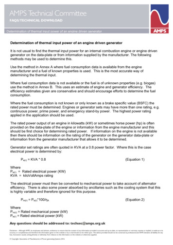
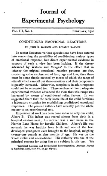
16 October 20073 Data Set 1For the first experimental data set, the data in Table 1 displays the values of the displacement versus thefrequency, the uncertainty in the values as well as the values of the distances between the mirrors and theglass plate.MirrorFrequency (Hz, σ 1 Hz)σ Frequency(Hz) X (m, σ 2.54e-4m)σ X (m)Least Squares Data-Fit:4 .184110.00060960.00081280.0002540.000254a (x0)b 110.00172720.0017780.0002540.000254Resulting Values:c3.00829E E 07576.510.00218440.000254 x x0 3.60617E-07Error Propagation:2 b2 r 2 D 2 16 2 2 222 c2 22 r D D r b brd 5.1198237615.0114σrσD0.02540.0254Table 1 - Data Set 1 Results and Error X (m) vs. Mirror Frequency (Hz) X Beam Deflection (m)0.0030.00250.0020.00150.001y 3.2105E-06x 5.0328E-04R² 9.3361E-010.000500100200300400500600700Mirror Rotation Frequency (Hz)Figure 2 - Data Set 1 Data PointsPage 6 of 9
16 October 2007The data collected was analyzed using a least-square fit method to obtain the value of b for the equation:x bf a(17)However, from Equation 16 it can be said then that:b 4πrdnaircc 4πrdnairbRearranging gives:(18)Therefore the speed of light can be found by using the known distances in the experimental setup as well asthe least-square fit of the data points collected. The value of b, along with the uncertainty in the value, wascalculated from the least-squares fit method using the data collected from the experiment. The values of rand d are listed in Table 1 along with their respective uncertainties in measurement.To find the uncertainty in the value of the speed of light Equation 18 was used in the error propagationderivational formula: c 2 c σ2D b b Dr2 2 2216πσb r Dσ2c 2 σ2r D2 σ2D r 2BB2σ2c σ2r c r2 σ2b2D(19)Where c is the relation in Equation 18. By using the least squares analysis along with the error propagationmethods, the result for the speed of light for the first data set was (3.008 0.34)x108 m/s.From the first experimental set, there were extra methods that would have allowed an increase in theprecision of the measurement. With the data analyzed, a second experimental set was recorded in order toreach a more accurate and precise value for the speed of light by taking a larger data set.4 Data Set 2For the second experiment, more data points were taken so that the uncertainty in the experiment wouldbe reduced. For each adjustment of the rotating mirror frequency, ten measurements of the position andthe frequency were taken so that an experimental uncertainty and average could be extracted, yielding amore precise and accurate result.Page 7 of 9
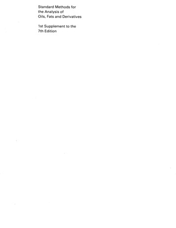
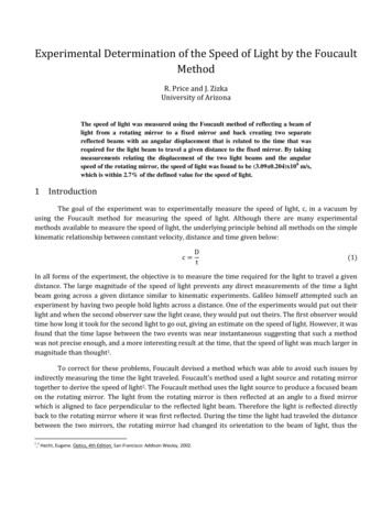
16 October 2007MirrorFrequency (Hz, σ 1 Hz)σ Frequency(Hz) X (m, σ 2.54e-4 m)σ dx 32194.020.8062222220.000670560.00019682Least Squares Data-Fit: x x0 4 rDfca (x0)b 2687Resulting Values:c3.09096E .0001909040.000192717σc2.04390E 07714.780.4262222220.002293620.000162882Error Propagation:2 b2 r 2 D 2 16 2 2 222 c2 22 r D D r b brd 5.1019215.01298σrσD0.0020.001587Table 2 - Data Set 2 Data Points X Deflection (m) vs. Mirror Frequency (Hz) X Beam Deflection (m)0.0030.00250.0020.0015y 3.1250E-06x 4.5966E-05R² ror Rotation Frequency (Hz)Figure 3 - Data Set 2 Data PlotUsing the process of error analysis and least-squares data fitting from the first data set, the second data sethad the result for the speed of light to be (3.091 0.204)x108 m/s.Page 8 of 9
16 October 20075 ResultsFrom the second data set, it was found that the speed of light is approximately (3.09 0.204)x108m/s. The experimental measurement is approximately within 2.7% compared to the actual value of cdefined as c 299,792,458 m/s. Also it should be noted that the defined value of c is within the bounds ofthe uncertainty of the experimental value, providing a sense of validity to the experimental method.The first data set produced a value of (3.00 0.34)x108 m/s, a 0.34% difference. Althoughsurprisingly accurate, the uncertainty is higher for the first data set in comparison to the second data set istherefore is considered less precise and less reliable. The second data set had ten times the amount of datapoints taken, which for the experiment would indicate it was closer to the defined value of c. Although thevalue of c is defined, for an experiment where the value in question is not known a priori it would beprudent to have trust in the value with the least uncertainty and more measurements.Although uncertainties of around 10% of the value exist from the experiment, it would be hardusing the existing methods to further reduce the values. It would require extremely precise measurementsto reach an uncertainty of 1%. For example, it would require taking distance measurements with anuncertainty of 0.1 mm and displacement measurements on the frosted screen of around 25 µm.Considering the average uncertainty of measurements using the microscope measurement device wasapproximately 200 µm from random uncertainty, reaching around 25 µm becomes a difficult task. Suchassumptions also assume that no other sources of error or experimental setup issues interfere with theexperiment itself. Eventually a newer method would have to be used in order to measure c more preciselypast three significant figures. One of the ways such an experiment could be improved was if the microscopemeasurements were replaced by a photo detector that was used to measure the intensity of the light as afunction of the distance across the glass plate and determine the position of the maximum intensity. Thephoto detector would have to be able to measure intensity over small sections of the glass plate, on theorder of a few microns, in order to decrease the uncertainty in the resulting value for the speed of light.Page 9 of 9
using a light sensor in conjunction with a frequency counter. As the mirror rotated with the laser positioned on it, there was an angle of the mirror that reflected the laser light beam toward the light sensor. When the laser beam was directed at the light sensor, it created a voltage which could be then measured by