Transcription
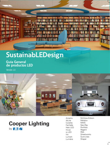
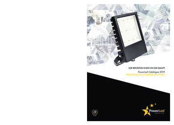
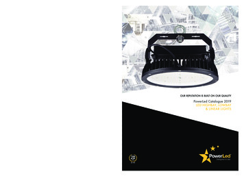
LED Dimming DriverEcoSystemTM 5-Series LED Driver - 5 – 75 W5% Dimming369823g 1 01.29.16EcoSystemTM 5-Series LED Driver — 5 W to 75 WEcoSystemTM 5-Series LED drivers provide ahigh‑performance solution for any space, in anyapplication, while providing smooth, continuousdimming down to 5% of full output current.Features Continuous, flicker-free dimming from 100% to 5%1. Guaranteed dimming performance when used withLutron controls. Guaranteed compatibility with Energi Savr NodeTMunits with EcoSystemTM, GRAFIK Eye QS withEcoSystemTM, PowPak dimming module withEcoSystemTM, and Quantum systems, allowing forintegration into a planned or existing EcoSystemTMlighting control solution. QwikFigTM compatible models available, see How toBuild a Model Number page for details. For moreinformation, please refer to the QwikFigTM UserGuide (Lutron P/N 041473) or contact your Lutronsales representative. Protected from miswires of input power toEcoSystemTM control inputs up to 277 V . A rated lifetime of 50,000 hours at 75 C (167 F)calibration point (tc). Type TL Rated2. FCC Part 15 compliant for commercial applicationsat 120—277 V 2. 100% performance tested at factory. RoHS compliant. Non-volatile memory restores all settings after powerfailure. For more information please visit:www.lutron.com/EcoSystem5Series 12EcoSystemTM LED Driver, case type M1.18 in (30 mm) W x 1.00 in (25 mm) H x 14.13 in (359 mm) LEcoSystemTM FeaturesSimpler to wire and more reliable than 0-10 V-.Guarantees compatibility between Lutron controls,drivers, and sensors.Accommodates zone changing without rewiring.Link to Lutron Quantum Total Light ManagementSystem to monitor lighting power consumption.Light output at 5% depends on the efficacy of the light engine used with the driver.Does not include J, K, L, M, and N output ranges (preliminary spec). Job Name:Job Number:S P E C I F I C AT I O N S U B M I T TA LModel Numbers:Page1
LED Dimming DriverEcoSystemTM 5-Series LED Driver - 5 – 75 W5% Dimming369823g 2 01.29.16Specifications 1234Regulatory ApprovalsLutron Quality Systems registered to ISO 9001.2008Manufacturing facilities employ ESD reductionpractices that comply with the requirements ofANSI / ESD S20.20Meets ANSI C62.41 category A surge protectionstandards up to and including 4 kVFCC Part 15 compliant for commercial applications at120—277 V 4Meets UL 8750, “Light Emitting Diode (LED)Equipment for use in Lighting Products”4Type TL rated4Class 2 output4Meets LED driver requirements forEnergy Star version 1.2PerformanceDimming Range: 100% to 5%1Operating Voltage: 120—277 V at 50 / 60 HzLifetime: 50,000 hours when calibration point (tc) at75 C (167 F)2For rated warranty, tc not to exceed 75 C (167 F)(maximum rated temperature)2Patented thermal foldback protectionLED lighting turns on to any dimmed level withoutflashing to full brightnessNon-volatile memory restores all driver settings afterpower failureTypical standby power consumption: 0.2 W at 120 V and 0.3 W at 277 V Open-circuit protected outputShort-circuit and overload-protected outputDevice turn-on time: 100 ms from electronic off and 500 ms from power off Class 2 output designed to withstand hot swap4 Inrush current less than NEMA 410-2011 limit4 Dimming method: constant-current reduction, refer toLutron Application Note #360 for detailsEnvironmental Sound rated: Class A inaudible in 24 dBA ambient Relative Humidity: maximum 90% non-condensing Minimum Operating Ambient Temperature:t a 0 C (32 F) 3 Indoor use only Rated for dry and damp locations Driver Wiring and MountingDriver is grounded by a mounting screw to thegrounded fixtureTerminal blocks on the driver accept one solid wire perterminal from 18 AWG to 16 AWG(0.75 mm2 to 1.5 mm2)Fixture must be grounded in accordance with localand national electrical codesMaximum driver-to-LED light engine wire length for:Maximum Lead LengthWire Gauge18 AWG (0.75 mm2)mm2)150 mA to700 mA710 mA to1.50 A1.51 A to2.10 A30 ft (9 m)15 ft (4.5 m)10 ft (3 m)35 ft (10.5 m)25 ft (7.5 m)15 ft (4.5 m)14 AWG (2.5 mm2)50 ft (15 m)40 ft (12 m)25 ft (7.5 m)12 AWG (4.0 mm2)100 ft (30 m)60 ft (18 m)40 ft (12 m)16 AWG (1.5* To use wire gauges larger than the terminal blocks’ rated gauge of18 to 16 AWG (0.75 mm2 to 1.5 mm2), refer to Terminal Wiring Gaugesdiagram. The 18 to 16 AWG (0.75 mm2 to 1.5 mm2) wires connectedto the driver should be less than 3 ft (0.9 m).Light output at 5% depends on the efficacy of the light engine used with the driver.To maintain warranty, installer is responsible for ensuring that the driver calibration point does not exceed 75 ºC (167 ºF).Where ta is the temperature of the air directly surrounding the driver.Does not include J, K, L, M, and N output ranges (Preliminary Spec). Job Name:Job Number:S P E C I F I C AT I O N S U B M I T TA LModel Numbers:Page2
LED Dimming DriverEcoSystemTM 5-Series LED Driver - 5 – 75 W5% Dimming369823g 3 01.29.16How to Select the Correct LED Driver for Your Load1. Review the specifications of the LED load.2. Identify the minimum and maximum operating voltage of the LED load at the desired operating current. This“current” will be the rated output current of the LED driver. Consult the LED load manufacturer for any questions.Example: An LED load that is rated at 1 A and 33 V nominally, has an output voltage range of 28 – 38 V (at1 A) due to unit-to-unit variation, temperature, etc.3. Determine the proper operating range of the LED driver.a. Identify the output range(s) of the driver family that includes the desired current.i. Select CurrentExample: Only “B”, “C”, “U”, and “V” models meet the current range of the selected load (1 A).LED Load Output RangeL 0.15 – 0.32 A, 20–40 V-, 5-10 WJ 0.15 – 0.30 A, 30–50 V-, 6-12 WM 0.25 – 0.50 A, 20–40 V-, 6.5-14 WK 0.24 – 0.50 A, 30–50 V-, 9-20 WN 0.35 – 0.75 A, 20–40 V-, 10-20 WT 0.40 – 0.83 A, 30–50 V-, 15-35 WB 0.50 – 1.25 A, 20–40 V-, 15-35 WU 0.70 – 1.33 A, 30–50 V-, 25-50 WC 0.88 – 1.75 A, 20–40 V-, 25-50 WV 1.00 – 1.88 A, 30–50 V-, 40-75 WD 1.25 – 2.10 A, 20–40 V-, 35-75 Wii. Select VoltageExample: Out of the 4 models indicated above, only “B” and “C” models meet the voltage requirement forthe selected load (28 – 38 V).LED Load Output RangeL 0.15 – 0.32 A, 20–40 V-, 5-10 WJ 0.15 – 0.30 A, 30–50 V-, 6-12 WM 0.25 – 0.50 A, 20–40 V-, 6.5-14 WK 0.24 – 0.50 A, 30–50 V-, 9-20 WN 0.35 – 0.75 A, 20–40 V-, 10-20 WT 0.40 – 0.83 A, 30–50 V-, 15-35 WB 0.50 – 1.25 A, 20–40 V-, 15-35 WU 0.70 – 1.33 A, 30–50 V-, 25-50 WC 0.88 – 1.75 A, 20–40 V-, 25-50 WV 1.00 – 1.88 A, 30–50 V-, 40-75 WD 1.25 – 2.10 A, 20–40 V-, 35-75 Wcontinued on next page Job Name:Job Number:S P E C I F I C AT I O N S U B M I T TA LModel Numbers:Page3
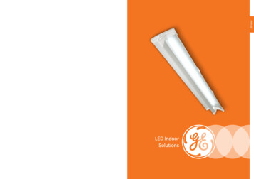
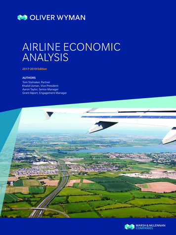
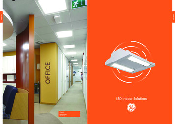
LED Dimming DriverEcoSystemTM 5-Series LED Driver - 5 – 75 W5% Dimming369823g 4 01.29.16How to Select the Correct LED Driver for Your Load (continued)b. Examine the Load Compatibility graphs below for each output range to ensure that the voltage range of theLED load is within the safe operating area.Example: L ines marked below indicate load specifications (28 – 38 V at 1 A).“B” Model (Not Compatible) “C” Model (Compatible)Since the maximum voltage of the load (38 V) exceeds theallowable voltage of “B” model (35 V at 1 A), this model isnot compatible.Load Compatibility4038 V353028 V}Operatingrange of 1 A,28 – 38 V load25201500.350.701.051.40Shaded area meets DLC Version 2.1 (areas outside ofshaded areas may not meet THD or PF requirements).Constant 15 W outputConstant 35 W output403530{38 VOperatingrange of 1 A,28 – 38 V load28 V2520150.351.75Output Current (A)Key:Load Compatibility45Output Voltage (V)Output Voltage (V)45 Operating voltage range for “C” model is 25 – 40 V at 1 A. Sincethe load specifications are within the operating range, “C” modelis compatible for this load.0.701.051.401.752.10Output Current (A)Key:Shaded area meets DLC Version 2.1 (areas outside ofshaded areas may not meet THD or PF requirements).Constant 25 W outputConstant 50 W output4. See How to Build A Model Number to create the appropriate model number for the desired driver. If aQwikFigTM compatible driver is needed, identify the proper LED Load Output Range (voltage and current) andinsert “BLK” in the Current Level (for Constant Current) section of the model number. Job Name:Job Number:S P E C I F I C AT I O N S U B M I T TA LModel Numbers:Page4
LED Dimming DriverEcoSystemTM 5-Series LED Driver - 5 – 75 W5% Dimming369823g 5 01.29.16How to Build a Model Number (“BLK” models for use with Lutron QwikFigTMtechnology): EcoSystemTM 5-Series (up to 75 W) LED DriverLD E5 U1U M N - AExample: LDE53U1UMN-BA0700.70 A, 15 – 28 W, 21.5 – 40 V- ** LED driverFor further assistance selecting your modelnumber, contact our LED Center of Excellenceat LEDs@lutron.comLED Load Output RangeClass 2 Constant CurrentL 0.15 – 0.32 A, 20 – 40 V- *, 5 – 10 WM 0.25 – 0.50 A, 20 – 40 V- *, 6.5 – 14 WN 0.35 – 0.75 A, 20 – 40 V- *, 10 – 20 WB 0.50 – 1.25 A, 20 – 40 V- *, 15 – 35 WC 0.88 – 1.75 A, 20 – 40 V- *, 25 – 50 WD 1.25 – 2.10 A, 20 – 40 V- *, 35 – 75 WJ 0.15 – 0.30 A, 30 – 50 V- *, 6 – 12 WK 0.24 – 0.50 A, 30 – 50 V- *, 9 – 20 WT 0.40 – 0.83 A, 30 – 50 V- *, 15 – 35 WU 0.70 – 1.33 A, 30 – 50 V- *, 25 – 50 WV 1.00 – 1.88 A, 30 – 50 V- *, 40 – 75 WLED Load Power Range1 Use when LED Load Output Range is “J,” “L,” or “M”2 Use when LED Load Output Range is “K” or “N”3 Use when LED Load Output Range is “B” or “T”5 Use when LED Load Output Range is “C” or “U”7 Use when LED Load Output Range is “D” or “V”Current Level (for Constant Current):015 0.15 A: . . . 210 2.10 AOption 1: Order a driver configured by Lutron to adesired output current.Example: LDE53U1UMN-BA070 has beenpre-configured at Lutron to anoutput of 0.70 A. Refer to theexample above.Note: LutronR pre-configured drivers are notQwikFigTM compatible and cannot bere-configured.Option 2: Order a QwikFigTM compatible driver.Example: LDE53U1UMN-BABLK (0.5 – 1.25 A)*Note: Default set to minimum output currentfor the respective LED Load Output Range. Attention: Model numbers may appear similar to Lutron Hi-lume A-Series drivers, but EcoSystemTM 5-Series drivers are not a direct model-for-modelreplacement for Hi-lume A-Series drivers. Please note the driver’s output rating and the load ratings to select the correct product for your fixture.Note: QwikFigTM bulk drivers are only available as UL recognized. Does not include “J,” “K,” “L,” “M,” and “N” output ranges.* Output voltage range changes with output current and according to power limits. Check driver specifications on following pages carefully tounderstand output voltage range of a particular SKU. Purchaser is responsible for electrical compatibility between LED driver and LED load.** Minimum voltage of LDE53U1UMN-BA070 limited by 15 W minimum power. Job Name:Job Number:S P E C I F I C AT I O N S U B M I T TA LModel Numbers:Page5
LED Dimming DriverEcoSystemTM 5-Series LED Driver - 5 – 75 W5% Dimming369823g 6 01.29.16“L” Output Range (preliminary spec)Driver TypeOutput Constant Current DriverConstant CurrentReduction (CCR)20—40 V-0.15—0.32 A*5—10 WStandardsRecognition—Maximum Rated Temp.@ tc for Warranty75 ºC* QwikFigTM compatible model number LDE51U1UMN-LABLK is configurable to any current within this range.Load CompatibilityHigh End Load Compatibility & DLC Compliance45453535Output Voltage (V)Output Voltage put Current (A)0.200.250.300.300.350.35Output Current (A) Job Name:Job Number:S P E C I F I C AT I O N S U B M I T TA LModel Numbers:Page6
LED Dimming DriverEcoSystemTM 5-Series LED Driver - 5 – 75 W5% Dimming369823g 7 01.29.16“M” Output Range (preliminary spec)Driver TypeOutput Constant Current DriverConstant CurrentReduction (CCR)20—40 V-0.25—0.50 A*6.5—14 WStandardsRecognition—Maximum Rated Temp.@ tc for Warranty75 ºC* QwikFigTM compatible model number LDE51U1UMN-MABLK is configurable to any current within this range.Load CompatibilityHigh End Load Compatibility & DLC Compliance45453535Output Voltage (V)Output Voltage 50.400.35 Current0.40Output(A)0.450.450.500.500.550.55Output Current (A) Job Name:Job Number:S P E C I F I C AT I O N S U B M I T TA LModel Numbers:Page7
LED Dimming DriverEcoSystemTM 5-Series LED Driver - 5 – 75 W5% Dimming369823g 8 01.29.16“N” Output Range (preliminary spec)Driver TypeOutput Constant Current DriverConstant CurrentReduction (CCR)20—40 V-0.35—0.75 A*10—20 WStandardsRecognition—Maximum Rated Temp.@ tc for Warranty75 ºC* QwikFigTM compatible model number LDE52U1UMN-NABLK is configurable to any current within this range.Load CompatibilityHigh End Load Compatibility & DLC Compliance4540403535Output Voltage (V)Output Voltage .60Output Current (A)0.700.700.800.80Output Current (A) Job Name:Job Number:S P E C I F I C AT I O N S U B M I T TA LModel Numbers:Page8
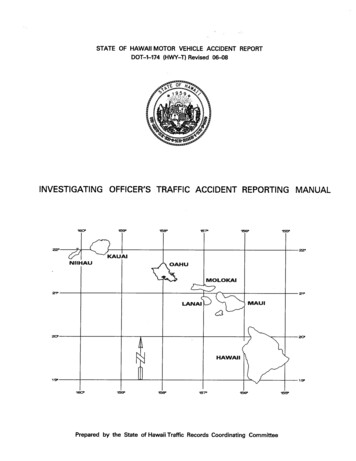
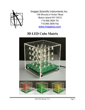
LED Dimming DriverEcoSystemTM 5-Series LED Driver - 5 – 75 W5% Dimming369823g 9 01.29.16“B” Output RangeDriver TypeOutput Constant Current Driver(Class 2)Constant CurrentReduction (CCR)20—40 V-0.50—1.25 A*15—35 WStandardsRecognitionMaximum Rated Temp.@ tc for Warranty75 ºCType TL 84 ºC / 65 ºC* QwikFigTM compatible model number LDE53U1UMN-BABLK is configurable to any current within this range.Typical Performance Specifications:ParameterValueTest ConditionsInput Current0.15 APower Factor0.96Vi 277 V , t a 25 C, Io 0.88 A, Vo 40 V-,Maximum Light OutputTHD15%Driver Efficiency85%LDE53U1UMN-BA088Typical Efficiency vs. Output CurrentLoad Compatibility90Efficiency at Pmax (%)Output Voltage ded area meets DLC Version 2.1 (areas outside ofshaded areas may not meet THD or PF requirements).Constant 15 W outputConstant 35 W outputTypical THD vs. Output Power277 V Typical Power Factor vs. Output PowerPower FactorTHD (%)120 V 1.00252015101.25Output Current (A)Output Current (A)Key:1.00152025300.950.900.85351520Output Power (W)Key:120 V Job Name:Job Number:277 V S P E C I F I C AT I O N S U B M I T TA LModel Numbers:253035Output Power (W)Key:120 V 277 V Page9
LED Dimming DriverEcoSystemTM 5-Series LED Driver - 5 – 75 W5% Dimming369823g 10 01.29.16“C” Output RangeDriver TypeOutput Constant Current Driver(Class 2)Constant CurrentReduction (CCR)20—40 V-0.88—1.75 A*25—50 WStandardsRecognitionMaximum Rated Temp.@ tc for Warranty75 ºCType TL 80 ºC / 76 ºC* QwikFigTM compatible model number LDE55U1UMN-CABLK is configurable to any current within this range.Typical Performance Specifications:ParameterValueTest ConditionsInput Current0.21 APower Factor0.97Vi 277 V , t a 25 C, Io 1.25 A, Vo 40 V-,Maximum Light OutputTHD13%Driver Efficiency88%LDE55U1UMN-CA125Typical Efficiency vs. Output CurrentLoad Compatibility90Efficiency at Pmax (%)Output Voltage ded area meets DLC Version 2.1 (areas outside ofshaded areas may not meet THD or PF requirements).Constant 25 W outputConstant 50 W outputTypical THD vs. Output Power277 V 1.00Power FactorTHD (%)120 V Typical Power Factor vs. Output Power20151051.75Output Current (A)Output Current (A)Key:1.4525303540450.950.900.85502530Output Power (W)Key:120 V Job Name:Job Number:277 V S P E C I F I C AT I O N S U B M I T TA LModel Numbers:35404550Output Power (W)Key:120 V 277 V Page10
LED Dimming DriverEcoSystemTM 5-Series LED Driver - 5 – 75 W5% Dimming369823g 11 01.29.16“D” Output RangeDriver TypeOutput Constant Current Driver(Class 2)Constant CurrentReduction (CCR)20—40 V-1.25—2.10 A*35—75 WStandardsRecognitionMaximum Rated Temp.@ tc for Warranty75 ºCType TL 82 ºC / 82 ºC* QwikFigTM compatible model number LDE57U1UMN-DABLK is configurable to any current within this range.Typical Performance Specifications:ParameterValueTest ConditionsInput Current0.31 APower Factor0.95Vi 277 V , t a 25 C, Io 1.88 A, Vo 40 V-,Maximum Light OutputTHD13%Driver Efficiency89%LDE57U1UMN-DA188Typical Efficiency vs. Output CurrentLoad Compatibility90Efficiency at Pmax (%)Output Voltage ded area meets DLC Version 2.1 (areas outside ofshaded areas may not meet THD or PF requirements).Typical THD vs. Output Power277 V 1.00Power FactorTHD (%)120 V Typical Power Factor vs. Output Power20151052.00Output Current (A)Output Current put Power (W)Key:120 V Job Name:Job Number:277 V S P E C I F I C AT I O N S U B M I T TA LModel Numbers:505560657075Output Power (W)Key:120 V 277 V Page11
LED Dimming DriverEcoSystemTM 5-Series LED Driver - 5 – 75 W5% Dimming369823g 12 01.29.16“J” Output Range (preliminary spec)Driver TypeOutput Constant Current Driver(Class 2)Constant CurrentReduction (CCR)30—50 V-0.15—0.30 A*6—12 WStandardsRecognition—Maximum Rated Temp.@ tc for Warranty75 ºC* QwikFigTM compatible model number LDE51U1UMN-JABLK is configurable to any current within this range.Load CompatibilityHigh End Load Compatibility & DLC Compliance5550504545Output Voltage (V)Output Voltage .20Output Current(A)0.300.300.350.35Output Current (A) Job Name:Job Number:S P E C I F I C AT I O N S U B M I T TA LModel Numbers:Page12
LED Dimming DriverEcoSystemTM 5-Series LED Driver - 5 – 75 W5% Dimming369823g 13 01.29.16“K” Output Range (preliminary spec)Driver TypeOutput Constant Current DriverConstant CurrentReduction (CCR)30—50 V-0.24—0.50 A*9—20 WStandardsRecognition—Maximum Rated Temp.@ tc for Warranty75 ºC* QwikFigTM compatible model number LDE52U1UMN-KABLK is configurable to any current within this range.Load CompatibilityHigh End Load Compatibility & DLC Compliance55554545Output Voltage (V)Output Voltage 50.350.400.40Output Current (A)0.450.450.500.500.550.55Output Current (A) Job Name:Job Number:S P E C I F I C AT I O N S U B M I T TA LModel Numbers:Page13
LED Dimming DriverEcoSystemTM 5-Series LED Driver - 5 – 75 W5% Dimming369823g 14 01.29.16“T” Output RangeDriver TypeOutput Constant Current Driver(Class 2)Constant CurrentReduction (CCR)30—50 V-0.40—0.83 A*15—35 WStandardsRecognitionMaximum Rated Temp.@ tc for Warranty75 ºCType TL 90 ºC / 64 ºC* QwikFigTM compatible model number LDE53U1UMN-TABLK is configurable to any current within this range.Typical Performance Specifications:ParameterValueTest ConditionsVi 277 V , t a 25 C, Io 0.70 A, Vo 50 V-,Maximum Light OutputInput Current0.15 APower Factor0.96THD13%Driver Efficiency87%LDE53U1UMN-TA070Load CompatibilityTypical Efficiency vs. Output Current90Efficiency at Pmax (%)Output Voltage (V)50454035300.250.500.758580750.401.000.50Output Current (A)Key:Key:Typical THD vs. Output Power120 V 277 V Typical Power Factor vs. Output Power1.00Power FactorTHD (%)0.80Constant 35 W output20151050.70Output Current (A)Shaded area meets DLC Version 2.1 (areas outside ofshaded areas may not meet THD or PF requirements).Constant 15 W output0.60152025300.950.900.85351520Output Power (W)Key:120 V Job Name:Job Number:277 V S P E C I F I C AT I O N S U B M I T TA LModel Numbers:253035Output Power (W)Key:120 V 277 V Page14
LED Dimming DriverEcoSystemTM 5-Series LED Driver - 5 – 75 W5% Dimming369823g 15 01.29.16“U” Output RangeDriver TypeOutput Constant Current Driver(Class 2)Constant CurrentReduction (CCR)30—50 V-0.70—1.33 A*25—50 WStandardsRecognitionMaximum Rated Temp.@ tc for Warranty75 ºCType TL 89 ºC / 64 ºC* QwikFigTM compatible model number LDE55U1UMN-UABLK is configurable to any current within this range.Typical Performance Specifications:ParameterValueTest ConditionsVi 277 V , t a 25 C, Io 1.0 A, Vo 50 V-,Maximum Light OutputInput Current0.21 APower Factor0.97THD11%Driver Efficiency86%LDE55U1UMN-UA100Typical Efficiency vs. Output CurrentLoad Compatibility90Efficiency at Pmax (%)Output Voltage :Shaded area meets DLC Version 2.1 (areas outside ofshaded areas may not meet THD or PF requirements).Constant 25 W outputConstant 50 W outputTypical THD vs. Output Power1.201.30120 V 277 V 1.00Power FactorTHD (%)1.10Typical Power Factor vs. Output Power20151051.00Output Current (A)Output Current (A)Key:0.9025303540450.950.900.85502530Output Power (W)Key:120 V Job Name:Job Number:277 V S P E C I F I C AT I O N S U B M I T TA LModel Numbers:35404550Output Power (W)Key:120 V 277 V Page15
LED Dimming DriverEcoSystemTM 5-Series LED Driver - 5 – 75 W5% Dimming369823g 16 01.29.16“V” Output RangeDriver TypeOutput Constant Current Driver(Class 2)Constant CurrentReduction (CCR)30—50 V-1.00—1.88 A*40—75 WStandardsRecognitionMaximum Rated Temp.@ tc for Warranty75 ºCType TL 89 ºC / 88 ºC* QwikFigTM compatible model number LDE57U1UMN-VABLK is configurable to any current within this range.Typical Performance Specifications:ParameterValueTest ConditionsInput Current0.31 APower Factor0.96Vi 277 V , t a 25 C, Io 1.5 A, Vo 50 V-,Maximum Light OutputTHD13%Driver Efficiency90%LDE57U1UMN-VA150Typical Efficiency vs. Output CurrentLoad Compatibility95Efficiency at Pmax (%)Output Voltage :Shaded area meets DLC Version 2.1 (areas outside ofshaded areas may not meet THD or PF requirements).Constant 35 W outputConstant 75 W outputTypical THD vs. Output Power277 V 1.00Power FactorTHD (%)120 V Typical Power Factor vs. Output Power20151051.75Output Current (A)Output Current (A)Key:1.50404550556065700.950.900.85754045Output Power (W)Key:120 V Job Name:Job Number:277 V S P E C I F I C AT I O N S U B M I T TA LModel Numbers:505560657075Output Power (W)Key:120 V 277 V Page16
LED Dimming DriverEcoSystemTM 5-Series LED Driver - 5 – 75 W5% Dimming369823g 17 01.29.16M Case: Case DimensionsCBAA14.13 in (359 mm)B 13.66 in (347 mm)(mounting center)C1.18 in (30 mm)D1.00 in (25 mm)D Job Name:Job Number:S P E C I F I C AT I O N S U B M I T TA LModel Numbers:Page17
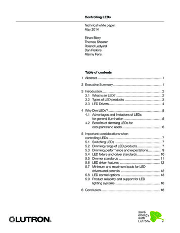
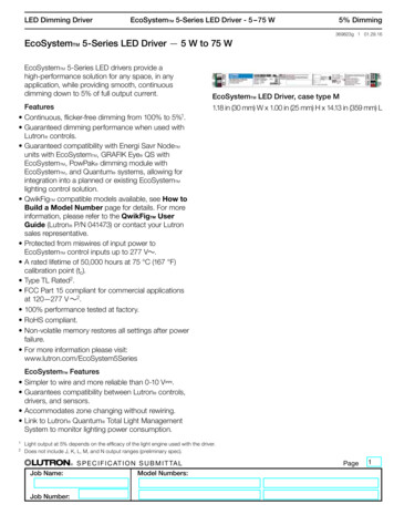
LED Dimming DriverEcoSystemTM 5-Series LED Driver - 5 – 75 W5% Dimming369823g 18 01.29.16Terminal Wiring GaugesNN/CLN/CN/CE1E2N/CN/CN/CN/C-VN/C VGround118 AWG to 16 AWG(0.75 mm2 to 1.5 mm2)18 AWG to 16 AWG(0.75 mm2 to 1.5 mm2)18 AWG to 16 AWG (0.75 mm2 to 1.5 mm2)18 AWG to 12 AWG(0.75 mm2 to 4.0 mm2)18 AWG to 12 AWG(0.75 mm2 to 4.0 mm2)18 AWG to 12 AWG (0.75 mm2 to 4.0 mm2)Wiring Diagram for EcoSystemTM Digital ControlHot (Black)ToLineVoltage V (Red)2Neutral (White)LEDLightEngineEcoSystemTM5-Series–V (Black)2Ground1E1 (Purple)ToEcoSystemTMDigital LinkE2 (Purple-White)Note: Colors shown correspond to terminal blocks on driver.1 Fixture and driver case must be grounded in accordance with local and national electrical codes; ground connection to driver must be accomplishedthrough grounding the case.2 For maximum driver-to-LED light engine wire length, see charts in the Driver Wiring and Mounting section. Job Name:Job Number:S P E C I F I C AT I O N S U B M I T TA LModel Numbers:Page18
LED Dimming DriverEcoSystemTM 5-Series LED Driver - 5 – 75 W5% Dimming369823g 19 01.29.16EcoSystemTM Wiring Diagrams NEcoSystemTM Digital Link OverviewThe EcoSystemTM Digital Link wiring (E1 and E2)connects the digital ballasts and drivers together toform a lighting control system.Sensors do not connect directly to EcoSystemTM5-Series LED drivers. Sensors are integrated throughthe EcoSystemTM controller.E1 and E2 (EcoSystemTM digital link wires) arepolarity‑insensitive and can be wired in any topology.Power is supplied to the EcoSystemTM Digital Link fromthe control system.EcoSystemTM Digital Link WiringEcoSystemTM Digital Link terminals accept only one18 AWG to 16 AWG (0.75 mm2 to 1.5 mm2) solidcopper wire per terminal.Make sure that the supply breaker to the drivers andEcoSystemTM Digital Link Supply is OFF when wiring.Connect the two conductors to the two driverterminals E1 and E2 as shown.Using two different colors for E1 and E2 will reduceconfusion when wiring several drivers together.The EcoSystemTM Digital Link may be wired Class 1 orClass 2. Consult applicable electrical codes for properwiring practices.For emergency wiring, please refer to Lutron Application Note #106.N/CLN/CN/CE1E2Driver TerminalsNN/CLN/CN/CE1E2Driver TerminalsTo the EcoSystemTM Digital Link Supplyand additional drivers and/or ballastsNotes The EcoSystemTM Digital Link Supply does not have tobe located at the end of the Digital Link. EcoSystemTM Digital Link length is limited by the wiregauge used for E1 and E2 as follows:Wire Gauge12 AWG*14 AWG*16 AWG18 AWGDigital Link Length (max)2200 ft1400 ft900 ft550 ftWire Size4.0 mm2*2.5 mm2*1.5 mm21.0 mm20.75 mm2Digital Link Length (max)828 m517 m310 m207 m155 m* To use wire gauges larger than the terminal blocks’ rated gauge of18 AWG to 16 AWG (0.75 mm2 to 1.5 mm2), refer to Terminal WiringGauges diagram. The 18 AWG to 16 AWG (0.75 mm2 to 1.5 mm2) wiresconnected to the driver should be less than 3 ft (0.9 m). Job Name:Job Number:S P E C I F I C AT I O N S U B M I T TA LModel Numbers:Page19
LED Dimming DriverEcoSystemTM 5-Series LED Driver - 5 – 75 W5% Dimming369823g 20 01.29.16EMC InformationThis device complies with part 15 of the FCC Rules.Operation is subject to the following two conditions: (1)This device may not cause harmful interference, and(2) this device must accept any interference received,including interference that may cause undesiredoperation.Note: This equipment has been tested and found tocomply with the limits for a Class A digital device,pursuant to part 15 of the FCC Rules. These limits aredesigned to provide reasonable protection againstharmful interference when the equipment is operatedin a commercial environment. This equipmentgenerates, uses, and can radiate radio frequencyenergy and, if not installed and used in accordancewith the instruction manual, may cause harmfulinterference to radio communications. Operation ofthis equipment in a residential area is likely to causeharmful interference in which case the user will berequired to correct the interference at his ownexpense.ServiceWarrantyFor warranty information, please nt PartsWhen ordering Lutron replacement parts, pleaseprovide the full model number. Consult Lutron if youhave any questions.Further InformationFor further information, please visit us atwww.lutron.com/EcoSystem5Series or contact ourLED Control Center of Excellence at 1.877.346.5338or LEDs@lutron.com Job Name:Job Number:S P E C I F I C AT I O N S U B M I T TA LModel Numbers:Page20
TM, and Quantum systems, allowing for integration into a planned or existing EcoSystem TM lighting control solution. gQwi Fik TM compatible models available, see How to Build a Model Number page for details. For more information, please refer to the QwikFig TM User Guide (Lutron P/N 041473) or contact your Lutron sales representative.