Transcription
Multidisciplinary Design Optimization ofAutomotive Aluminum Cross-Car Beam AssemblybyMohsen RahmaniA thesis submitted in conformity with the requirementsfor the degree of Masters of Applied ScienceGraduate Department of Mechanical and Industrial EngineeringUniversity of Toronto Copyright by Mohsen Rahmani 2013
Multidisciplinary Design Optimization of Automotive AluminumCross-Car Beam AssemblyMohsen RahmaniMasters of Applied ScienceGraduate Department of Mechanical and Industrial EngineeringUniversity of Toronto, 2013AbstractAluminum Cross-Car Beam is significantly lighter than the conventional steel counterpart andpresents superior energy absorption characteristics. The challenge is however, its considerablyhigher cost, rendering it difficult for the aluminum one to compete in the automotive market.In this work, using material distribution techniques and stochastic optimization, aMultidisciplinary Design Optimization procedure is developed to optimize an existing CrossCar Beam model with respect to the cost. Topology, Topography, and gauge optimizations areemployed in the development of the optimization disciplines. Based on a qualitative costassessment, penalty functions are designed to penalize costly designs. Noise-VibrationHarshness (NVH) performance is the key constraint of the optimization. To fulfill thisrequirement, natural frequencies are obtained using modal analysis. Undesirable designs withrespect to the NVH criteria are gradually eliminated from the optimization cycles. The newdesign is verified by static loading scenario and evaluated in terms of the cost saving it offers.ii
AcknowledgementsCompleting this work would not have been possible without the help and support of severalwonderful people. First and foremost, I would like to present my deep gratitude to myprincipal supervisor Dr. Kamran Behdinan for providing me with the opportunity to work onthis project and to learn from him. His guidance, patience, and encouragement through theduration of my Master’s program are most appreciated. Apart from the academic side, Ialways see him as an inspiring person in my personal life.My sincere appreciation goes to my supportive co-supervisor Dr. Jean Zu. She was serving asthe chair of the department in the period of my program and I cannot forget the time andenergy she devoted to our work considering her busy schedule and limited time.This project is sponsored by Van-Rob Inc. and I have learned a lot through this collaboration.I would like to acknowledge the help from Van-Rob specialists. My special thanks areexpressed to Dr. Sacheen Bekah from Van-Rob for the useful discussions and for providingme with creative suggestion and comments.I should also express my appreciation for the members of the Advanced Research Laboratoryfor Multifunctional Lightweight Structures at the Department of Mechanical and IndustrialEngineering. Being among these bright and warm people has made my experience moreenjoyable. I have had the pleasure of friendship of many beautiful people at the University ofToronto. I wish to thank them for their kindliness and I consider our companionship aninordinate gift I received during the time span of this program.Last but definitely not least, I owe the completion of this work to my family. Even though wehave been miles away in the past two years, my father, my mother and my sisters have beenthe greatest sources of motivation for me. Their deep love, understanding and continuoussupport has certainly made me to be better in what I am doing. It is to them that this thesis isdedicated.iii
ContentsAbstract. iiAcknowledgements . iiiList of Tables . viiList of Figures . viiiList of Appendices .xNomenclature. xiCHAPTER 1: INTRODUCTION .11.1 Aluminum in Automotive Industry .11.2 Advantages of Aluminum .31.3 Instrument Panel (IP) System and Cross-Car Beam (CCB) Assembly.61.4 Objectives . 101.5 Thesis Outline . 11CHAPTER 2: THEORETICAL FOUNDATIONS . 132.1 Noise-Vibration-Harshness (NVH) Analysis . 132.1.1 Modal Analysis . 132.1.2 Noise-Vibration-Harshness (NVH) Performance Evaluation and Testing . 152.2 Multidisciplinary Design Optimization (MDO) . 162.2.1 Aeroelastic Optimization of a Wing . 182.2.2 Multidisciplinary Design Optimization (MDO) Architectures . 202.2.3 Multi-Disciplinary Feasible (MDF) Algorithm . 222.2.4 Individual Disciplinary Feasible (IDF) Algorithm . 232.2.5 All-at-Once (AAO) Algorithm . 252.3 Material Distribution Method for Design . 272.3.1 Topology Optimization . 282.3.2 Topography Optimization . 312.4 Cross-Car Beam (CCB) Assembly Optimization . 33iv
CHAPTER 3: MULTIDISCIPLINARY DESIGN OPTIMIZATION . 373.1 Finite Element Model . 373.2 Optimization Objective and Constraints . 413.3 Modal Analysis of the Cross-Car Beam Assembly . 423.4 Sensitivity Analysis of the Parts . 433.5 Multidisciplinary Design Optimization Architecture. 463.5.1 Gauge Discipline . 473.5.2 Shape Discipline . 473.5.3 Part Discipline . 523.5.4 Integration of Disciplines . 573.6 Cost Estimation . 613.7 Particle Swarm Optimization (PSO) . 62CHAPTER 4: IMPLEMENTATION OF MULTIDISCIPLINARY DESIGNOPTIMIZATION . 664.1 Implementation Process . 664.1.1 Preparing the Finite Element Model . 664.1.2 Calling the RADIOSS Solver . 694.1.3 Collecting the Responses . 694.2 Fitness Function and Constraints Handling . 694.3 Algorithm Stopping Criteria . 72CAHPTER 5: RESULTS AND DISCUSSION . 755.1 Optimum Design . 755.1.1 Gauge Thicknesses . 795.1.2 Shape Morphing Optimum Values . 805.1.3 Part Selection . 815.2 Statistics of the Results. 835.3 Mass Reduction and Cost Saving . 84v
5.3.1 Mass Reduction . 845.3.1 Estimated Cost Reduction . 865.4 Static Analysis of the Cross-Car Beam (CCB) Assembly . 87CHAPTER 6: CONCLUSIONS AND RECOMMENDATIONS . 906.1 Concluding Remarks . 906.2 Future Directions. 91REFERENCES . 93vi
List of Tables1-1Aluminum content of several aluminum intensive vehicles (2012 models) [4]23-1Mechanical and physical properties of the Aluminum alloys used in the CCB373-2FE details of the entire model including the CCB403-3Sensitivity data of the main parts with regard to changes in the thickness454-1Part configurations based on the corresponding design variable values684-2Different types of stopping criteria. Based on Ref. [57]735-1Summary of optimization results for 10 trials765-2Optimum gauge thickness for 10 trials (all in millimeters)795-3Optimum Shape Coefficients for 10 trials815-4Optimum part selections for 10 trials825-5Statistical analysis of the fitness values for different population sizes835-6Statistical analysis of the CCB mass values for different population sizes845-7Passenger cars sold in US and Canada. Obtained from Ref. [39]875-8Tube static load analysis results89vii
List of Figures1-1Aluminum content in pounds per light vehicles in North America, history andforecast [5]31-2Passenger vehicles’ average fuel economy [7]41-3Passenger vehicles’ GHG emissions regulations [7]51-4Summary of aluminum-intensive automotive advantages. Inspired by Ref. [6]61-5Sample IP complex with the steering column mounted on it [8]71-6The CCB (shaded area) as the skeleton of the IP system [9]82-1Pendulum in free vibration132-2Multidisciplinary problem consisting of N subsystem. Adopted from Ref. [12]182-3Multidisciplinary Optimization of the Aeroelastic system192-4MDF architecture. Adopted from Ref. [12]232-5IDF architecture. Adopted from Ref. [12]242-6AAO architecture. Adopted from Ref. [12]262-7Material distribution method272-8Common numerical problems pertaining to the topology optimization312-9Bead patterns on a suspension support created by topography optimization.Obtained from Ref. [30]332-10Design Sensitivity Analysis method for the CCB design. Adopted from Ref. [35]35viii
3-1Finite Element model of the CCB assembly383-2CCB main parts and leading load path of the assembly443-3Bead characteristics483-4Topography optimization results for (a) DS VB and (b) PS VB493-5DS Tube (a) before shape morphing and (b) after shape morphing503-6PS Tube (a) before shape morphing and (b) after shape morphing503-7DS Vertical Brace (a) before shape morphing and (b) after shape morphing513-8PS Vertical Brace (a) before shape morphing and (b) after shape morphing513-9Topology optimization of Cowl Top part533-10Two distinct designs of the Cowl Top543-11Three distinct design of the DS End Bracket553-12Two distinct designs of the DS Tube563-13Two distinct designs of the DS Vertical Brace573-14The MDO procedure for CCB optimization605-1Convergence history for optimization trials using population size of 15775-2Convergence history for optimization trials using population size of 10785-3Mass reduction associated with various design trials855-4Static load analysis of the CCB tube885-5Stress distribution of the CCB under the static load89ix
List of AppendicesAppendix A: Element Specifications99Appendix B: Mass Reduction History Diagrams101Appendix C: Matlab Codes103x
NomenclatureOEMOriginal Equipment ManufacturerAIVAluminum Intensive VehicleMPGMile per GallonGHGGreen House GasCAFECorporate Average Fuel EconomyCCBCross-Car beamMIGMetal Inert GasNVHNoise, Vibration and HarshnessDOFDegree of FreedomPDEPartial Differential EquationFEFinite ElementMDOMultidisciplinary Design OptimizationMDFMultidisciplinary FeasibleIDFIndividual Discipline FeasibleAAOAll At Oncexi
FPIFixed Point IterationSIMPSolid Isotropic Material with PenalizationYYoung ModulusPoisson’s RatioCADComputer Aided DesignAMLSAutomatic Multi-level Sub-structuringDSDriver SidePSPassenger SideC.V.Coefficient of Variationxii
CHAPTER 1: INTRODUCTION1.1 Aluminum in Automotive IndustryThe idea of using light weight structures in the automotive industry is nourished by the needfor enhancing the vehicle performances. Simply said, a lighter vehicle needs less power tomove and consumes less energy per unit distance traveled. Traditionally, steel and cast ironwere used to produce the majority of the vehicle components. However, today’s cars arevastly reliant on non-ferrous materials as well, with the most common metal among thembeing aluminum alloys.Car manufacturers began using aluminum in the cars over a century ago when people in theBerlin International Motor Show observed for the first time a sport car featuring a body madeof aluminum in 1899. At that time, the technology for extracting and forming aluminum wasstill rudimentary. Therefore, it was not cost-efficient to fundamentally include aluminum inthe designs. However, the light weight and excellent corrosion resistance properties of themetal helped it to make its way into the automotive industry [1].Upon proclaiming an oil embargo in 1973 by members of OAPEC known as the Oil Crisis,car manufacturers started to search for novel ways of fuel saving. It turned out that the mosteffective action to lower the fuel consumption is to reduce the weight of the cars sinceaccording to rough calculations, reducing the weight of a medium-sized vehicle by 100 Kgcauses a 700 liters reduction in fuel consumption during a typical vehicle’s lifespan.Motivated by such facts, using lighter designs experienced a significant growth amongst themanufacturers. Nowadays a typical car contains an average of 110-145 Kg of aluminum [1].Original Equipment Manufacturers (OEM) now strive for higher fuel economy and lowerharmful emissions by investing more in the so called Aluminum Intensive Vehicle (AIV).1
AIVs comprise of considerable amounts of aluminum sheets and extruded wrought alloys intheir structure [2]. Aluminum is used in a variety of components in a vehicle including thewheels, radiators, condensers, and body. Audi played the role of pioneer for OEMs byreleasing its A8 model with complete aluminum body in 1994. The company developed AudiSpace Frame principle to support creating large aluminum sheet elements to becomeintegrated as load-bearing structures. The Audi A8 Space Frame weighs only 249 Kg which isalmost 200 kg less than a steel counterpart of the same class. Mass production of an allaluminum body vehicle was truly a milestone in the automotive industry. Later on Audilaunched Audi A2 as the next generation of all-aluminum cars with a body weighing 156 Kg.That is to say, 43 percent lighter than conventional steel body. Audi A2 consumes only 3liters of diesel oil per 100 Km. So far, more than 150,000 aluminum car have been producedby Audi consisting of both A8 and A2 [3].Table 1-1 presents some of the 2012 models with a minimum of 10% aluminum curb weight.The total weight of a vehicle including all the necessary equipment and a full tank of oil andexcluding any load and passenger is referred to as the curb weight.Table 1-1 Aluminum content of several aluminum intensive vehicles (2012 models) [4]VehicleAluminum PercentageAluminum PoundsMercedes-Benz ML-Class11.60581Saab 9-4X11.60406Chrysler/Fiat C-Sedan11.30351Lincoln MKZ11.30397Chevrolet Malibu11.20385Nissan Altima11.10355Ford Escape10.90355Honda CR-V10.90290Dodge Viper (ZD)10.703692
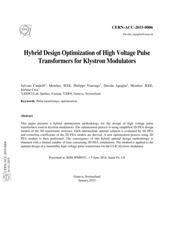
Ducker Worldwide has been collecting records on the growth of aluminum usage in lightvehicle applications on an annual basis since 1991. Figure 1-1 represents the aluminumcontent in light vehicles in North America from 1975 to 2011 and the anticipated amount upto 2025. The forecasted aluminum content for 2025 is approximately 16% of curb weightwhich can be achieved by 3.5% aluminum growth rate in the period of 1990 to 2025.However, this prediction is considered to be conservative [5].Figure 1-1 Aluminum content in pounds per light vehicles in North America, history and forecast [5]1.2 Advantages of AluminumUsing aluminum components in cars and trucks is persistently growing. This is primarily dueto light weight, high strength, and environment friendly characteristics of aluminum alloys.Employing the light metal in the vehicles allows for reducing the weight without downsizingthe vehicle, i.e. having the same car with a lower weight. This is specifically an importantmerit and goal in electric cars. The most challenging concern in the performance of electriccars is the large and heavy batteries necessary to empower the car to travel reasonably longdistances without demanding a battery recharge. It is estimated that an electric car can roughlytravel the same extra percentage as the percentage of the reduced weight, e.g. if the vehicle is3
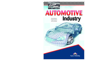
lightened by 20%, it is expected to travel an extra 20% distance without additional powersupply [6].The weight reduction of vehicles can be recognized as being primary or secondary. Theprimary weight reduction is the direct reduction of the body weight as a consequence ofutilizing a lighter alloy. A secondary weight reduction can then be attained in the engine,drive train, and chassis since the lightened vehicle needs less power to propel.A main driver for further usage of light materials in the cars is coming from the evertoughening regulations on Mile per Gallon (MPG) fuel economy and Green House Gas(GHG) emission for vehicles. Every year the vehicles are expected to have higher MPGvalues and lower GHG amounts. The following Corporate Average Fuel Economy (CAFE)chart represents the fuel economy regulations in different regions, both history and theforecasted extents. It is inferred from Figure 1-2 that European and Japanese cars are requiredto have significantly higher MPG values compared to the rest of the regions. This is mainlydue to the smaller sizes of these cars. The Canadian fuel economy is more or less similar tothe US requirements as the North America market is fed mainly by the same car companies.Figure 1-2 Passenger vehicles’ average fuel economy [7]4
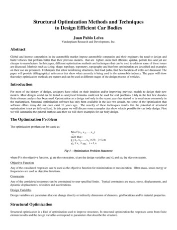
A lighter car needs less fuel and produces a smaller amount of CO2 gas, therefore preservingthe environment from being polluted by harmful emissions. Figure 1-3 represents therequirement on the GHG emission for car manufacturers of different regions. Considering thisdiagram, one can realize that the GHG emissions in all regions are expected to shrinkdrastically from the current state to the 2030 predictions.Figure 1-3 Passenger vehicles’ GHG emissions regulations [7]Aluminum can be easily and efficiently recovered and recycled forever. From all aluminumproduced since 1888, almost 75% of it is still in use [6]. When the AIVs life is ended, theywill be dismantled and recycled in recycling infrastructures capable to recycle more than 75%of the materials in the vehicle [2].Another key feature of this light metal is its great performance in the crash. Intelligent designshave been made possible using high-strength aluminum alloys that can absorb the destructivecrash force by permanent deformation into the expected patterns. Furthermore, a larger bodyis generally safer in crash. Using aluminum, the vehicle weight can be reduced whilemaintaining its size; hence it provides a safer crash experience [6].5
There are more and more advantages which come with utilizing aluminum alloys. Figure 1-4emphasizes some of the most significant advantages that follow aluminum-intensiveautomotive designs.Efficiency A 5-7% fuel saving can be realized for each 10% of weight reduction Using the same battery, the range of electric vehicles can be increasedSustainability More than 75% of the aluminum used in automotive is recovered Recycling aluminum requires only 5% of the primary production energySafety High-strength aluminum shows superior impact energy absorbsion The structures can be designed to fold as predicted during the crashDurability Aluminum products are long-lasting and rust-resistant They are strong enough to be used even in rough military applicationsHigh-Performance Lighter vehicles have a faster acceleration and shorter break distances Its design flexibility enables the engineer to design for optimum shapesCost-Effective It is impossible to achieve 50 mpg target without reducing the weight Up to 3000 per unit can be saved in electric cars using fewer batteriesFigure 1-4 Summary of aluminum-intensive automotive advantages. Inspired by Ref. [6]1.3 Instrument Panel (IP) System and Cross-Car Beam (CCB) AssemblyThe Instrument Panel (IP) is a collection of different modules each responsible for an aspectof the performance, control, and safety of the vehicle. It is referred to the front part of thevehicle interior where the steering column, airbags, glove-box, etc. are located. A typical IP ofa car is depicted in Figure 1-5. There are many essential sub-systems that are tightly packed inthe IP complex; hence the IP as a whole is a compound multi-functional system. Since it islocated immediately in front of the driver and the passenger in the front seat, there are certainsafety concerns that need to be accounted for in the design of the IP. Furthermore, each of the6
main sub-systems requires its special design considerations and its local design constraintsneed to be satisfied.Figure 1-5 Sample IP complex with the steering column mounted on it [8]The IP exterior is an enclosure typically made from light composites. Being light weight anddurable is a key factor in the design of the IP system. Furthermore, it is also critical toconsider the event of crash; the material used in the IP should cause the minimum harmpossible when crashed under the forces of a collision. Esthetic considerations affect thematerial selection and design as well.In the heart of the IP there is a metallic support structure to bear the loads and partly respondto crash forces. This metallic frame is designated as the Cross-Car Beam (CCB) assembly.Figure 1-6 depicts an IP system with the CCB assembly represented as a shaded structureinside the IP. The CCB constitutes of many parts, each of them serving a special requisite inthe structure. Steering column support brackets, knee bolster supports, end brackets, airbagsupports, and cowl top are among the main CCB parts [9].7
The main functions of the CCB can be described in a number of points: The CCB is the load path that transfers the weight of the steering column to the bodythrough its junctions with the car body on sides, top and the bottom. The two ends ofthe CCB meet the A-Pillars on the sides. It acts as a skeleton for the IP complex and integrates various parts into the assembly.There are several supplementary components attached to the CCB (not shown inFigure 1-6) each serving as the support for a sub-system, e.g. the airbag. On the occurrence of a crash it is the responsibility of the CCB and its energyabsorbers to deform under the crash force and prevent the occupants fromexperiencing the severe impact force. It is a main component of the car body frame contributing to its overall integrity andstiffness and affecting the frequency response of the entire vehicleFigure 1-6 The CCB (shaded area) as the skeleton of the IP system [9]8
Traditionally, mild steel is the material used to build the parts of the CCB assembly. Themajority of the components are produced by stamping sheets; however, there are a few partsthat are manufactured by extrusion. The parts are eventually attached together by laserwelding and Metal Inert Gas (MIG) welding to form the CCB assembly. Efforts have beenmade to fabricate CCB supports using injection molding and one-piece die castingtechnologies. Although the cost of welding can be saved using these technologies, thematerial and tooling cost of such designs may be prohibitive for their volume production [9].Similar to other components of vehicles, the need for weight reduction which is supported bythe demand for higher fuel efficiency has made its impact on the design of CCB. AluminumCCBs tend to substitute the steel ones thank to the excellent energy absorbance and lightweight of aluminum alloys. Although aluminum CCB weighs roughly half of a steel one andhence offers great mass reduction, fulfilling the performance requirements of the CCB can bemore challenging for the aluminum CCB. The main constraints in the design of CCB arerecognized as the Noise-Vibration-Harshness (NVH) and the crashworthiness performances.It is essential to meet the specific criteria describing each of these constraints.The NVH performance is concerned about the natural frequencies of the structure and keepingthem securely detached from the frequencies of prevailing excitement sources. The engine,power transmission system, and the road surface are common resources for vibration. If thenatural frequencies of the CCB structure overlap with one of the excitement frequencies aphenomenon known as resonance occurs. In resonance, the amplitude of the vibration can govery large (theoretically it can go to infinity). Such high-amplitude vibrations can producesignificant annoying noise inside and outside of the car. It can also be transmitted to thesteering column and cause discomfort and distraction to the driver too [9]. To avoid thisdestructive phenomenon the modal response of the CCB assembly should be studied andmodified as required.The second constraint deals with the ability of the structure to absorb undesirable forces in theevent of a crash. The airbag absorbs a significant portion of the energy and plays a vital key inprotecting the driver. However, the energy absorbers are also critical to protect the driver’sknees when the collision happens. If they don’t absorb adequate energy it becomes likely for9
the knee bolster to move upward and come in contact with the steering column. This causesthe steering column to rotate and remove the airbag from its proper location and orientation,therefore jeopardizing the safety of the occupants [9].To guarantee the safety of the driver and passenger in the front seat, regulations have beendeveloped by OEMs to examine the performance of the vehicle in crash. There are differentcrash tests such as frontal crash and side crash that need to be performed on every vehiclebefore its mass production.Apart from the tests that evaluates the crash performance of the car as a whole, the parts andassemblies that have a prominent role in the safety of the occupants need to be tested andevaluated individually in the design and development stages. The CCB employs the energyabsorbers and knee bolsters for controlling the impact energy and damping the forcetransmitted to the occupants. In the crashworthiness evaluation the full CCB assembly issubjected to various simulated impacts and the maximum deformation of the components isassessed as a measure for crash performance.1.4 ObjectivesThe aluminum CCB can overtake the steel counterparts considering the continuouslytoughening fuel economy and emission regulations. That is, the essential direction to reachsuperior fuel efficiency is weight reduction and it can be achieved by substituting theconventional designs with modern ones using light weight alloys. However, employing thealuminum CCB in the vehicles is still cost-intensive. It typically costs about twice the mildsteel CCB.The common treatment in automotive engineering to reduce the cost of components is tolighten them. It is well appreciated that the weight contributes greatly to the cost of thestructure. However, the cost is not merely a function of the weight. The manufacturingcomplication of the parts and the attachment tools are other causative aspects to beconsidered. Considering the complexity of the CCB assemb
The constraint of the optimization problem is NVH performance of the CCB. It is required that the first two natural frequencies of the CCB remain greater or equal to 38 Hz and 40 Hz respectively. The baseline model has natural frequencies equal to 39.05 Hz and 41.60 Hz respectively. The constraint handling method used is additive penalty functions.