Transcription
Chapter 5 – System ModelingSummaryChapter 5 System modeling1
Topics covered Context modelsInteraction modelsStructural modelsBehavioral modelsModel-driven engineeringChapter 5 System modeling2
System modeling System modeling is the process of developingabstract models of a system, with each modelpresenting a different view or perspective of thatsystem. System modeling has now come to meanrepresenting a system using some kind of graphicalnotation, which is now almost always based onnotations in the Unified Modeling Language (UML). System modelling helps the analyst to understandthe functionality of the system and models are usedto communicate with customers.Chapter 5 System modeling3
Existing and planned system models Models of the existing system are used during requirementsengineering. They help clarify what the existing system does andcan be used as a basis for discussing its strengths and weaknesses.These then lead to requirements for the new system. Models of the new system are used during requirementsengineering to help explain the proposed requirements to othersystem stakeholders. Engineers use these models to discuss designproposals and to document the system for implementation. In a model-driven engineering process, it is possible to generate acomplete or partial system implementation from the system model.Chapter 5 System modeling4
System perspectives An external perspective, where you model the context orenvironment of the system. An interaction perspective, where you model theinteractions between a system and its environment, orbetween the components of a system. A structural perspective, where you model theorganization of a system or the structure of the data thatis processed by the system. A behavioral perspective, where you model the dynamicbehavior of the system and how it responds to events.Chapter 5 System modeling5
UML diagram types Activity diagrams, which show the activities involved in aprocess or in data processing . Use case diagrams, which show the interactions betweena system and its environment. Sequence diagrams, which show interactions betweenactors and the system and between system components. Class diagrams, which show the object classes in thesystem and the associations between these classes. State diagrams, which show how the system reacts tointernal and external events.Chapter 5 System modeling6
Use of graphical models As a means of facilitating discussion about an existingor proposed system– Incomplete and incorrect models are OK as their role is tosupport discussion. As a way of documenting an existing system– Models should be an accurate representation of thesystem but need not be complete. As a detailed system description that can be used togenerate a system implementation– Models have to be both correct and complete.Chapter 5 System modeling7
Context models Context models are used to illustrate the operationalcontext of a system - they show what lies outside thesystem boundaries. Social and organisational concerns may affect thedecision on where to position system boundaries. Architectural models show the system and itsrelationship with other systems.Chapter 5 System modeling8
System boundaries System boundaries are established to define what isinside and what is outside the system.– They show other systems that are used or depend on thesystem being developed. The position of the system boundary has a profoundeffect on the system requirements. Defining a system boundary is a political judgment– There may be pressures to develop system boundaries thatincrease / decrease the influence or workload of differentparts of an organization.Chapter 5 System modeling9
The context of the MHC-PMSChapter 5 System modeling10
Process perspective Context models simply show the other systems in theenvironment, not how the system being developed isused in that environment. Process models reveal how the system beingdeveloped is used in broader business processes. UML activity diagrams may be used to definebusiness process models.Chapter 5 System modeling11
Process model of involuntary detentionChapter 5 System modeling12
Interaction models Modeling user interaction is important as it helps toidentify user requirements. Modeling system-to-system interaction highlights thecommunication problems that may arise. Modeling component interaction helps usunderstand if a proposed system structure is likely todeliver the required system performance anddependability. Use case diagrams and sequence diagrams may beused for interaction modeling.Chapter 5 System modeling13
Use case modeling Use cases were developed originally to supportrequirements elicitation and now incorporated intothe UML. Each use case represents a discrete task that involvesexternal interaction with a system. Actors in a use case may be people or other systems. Represented diagramatically to provide an overviewof the use case and in a more detailed textual form.Chapter 5 System modeling14
Transfer-data use case A use case in the MHC-PMSChapter 5 System modeling15
Tabular description of the ‘Transfer data’ usecaseMHC-PMS: Transfer dataActorsMedical receptionist, patient records system (PRS)DescriptionDataA receptionist may transfer data from the MHC-PMS to ageneral patient record database that is maintained by ahealth authority. The information transferred may eitherbe updated personal information (address, phonenumber, etc.) or a summary of the patient’s diagnosisand treatment.Patient’s personal information, treatment summaryStimulusUser command issued by medical receptionistResponseConfirmation that PRS has been updatedCommentsThe receptionist must have appropriate securitypermissions to access the patient information and thePRS.Chapter 5 System modeling16
Use cases in the MHC-PMS involving the role‘Medical Receptionist’Chapter 5 System modeling17
Sequence diagrams Sequence diagrams are part of the UML and are used tomodel the interactions between the actors and theobjects within a system. A sequence diagram shows the sequence of interactionsthat take place during a particular use case or use caseinstance. The objects and actors involved are listed along the topof the diagram, with a dotted line drawn vertically fromthese. Interactions between objects are indicated by annotatedarrows.Chapter 5 System modeling18
Sequence diagram for View patient informationChapter 5 System modeling19
Sequence diagram for Transfer DataChapter 5 System modeling20
Structural models Structural models of software display theorganization of a system in terms of the componentsthat make up that system and their relationships. Structural models may be static models, which showthe structure of the system design, or dynamicmodels, which show the organization of the systemwhen it is executing. You create structural models of a system when youare discussing and designing the system architecture.Chapter 5 System modeling21
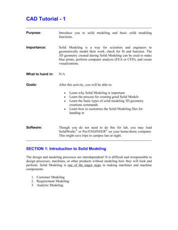
Class diagrams Class diagrams are used when developing an object-orientedsystem model to show the classes in a system and theassociations between these classes. An object class can be thought of as a general definition ofone kind of system object. An association is a link between classes that indicates thatthere is some relationship between these classes. When you are developing models during the early stages ofthe software engineering process, objects representsomething in the real world, such as a patient, a prescription,doctor, etc.Chapter 5 System modeling22
UML classes and associationChapter 5 System modeling23
Classes and associations in the MHC-PMSChapter 5 System modeling24
The Consultation classChapter 5 System modeling25
Key points A model is an abstract view of a system that ignores system details.Complementary system models can be developed to show the system’scontext, interactions, structure and behavior. Context models show how a system that is being modeled is positioned inan environment with other systems and processes. Use case diagrams and sequence diagrams are used to describe theinteractions between users and systems in the system being designed. Usecases describe interactions between a system and external actors;sequence diagrams add more information to these by showinginteractions between system objects. Structural models show the organization and architecture of a system.Class diagrams are used to define the static structure of classes in asystem and their associations.Chapter 5 System modeling26
Generalization Generalization is an everyday technique that we useto manage complexity. Rather than learn the detailed characteristics ofevery entity that we experience, we place theseentities in more general classes (animals, cars,houses, etc.) and learn the characteristics of theseclasses. This allows us to infer that different members ofthese classes have some common characteristics e.g.squirrels and rats are rodents.Chapter 5 System modeling27
Generalization In modeling systems, it is often useful to examine the classes in asystem to see if there is scope for generalization. If changes areproposed, then you do not have to look at all classes in the system tosee if they are affected by the change. In object-oriented languages, such as Java, generalization isimplemented using the class inheritance mechanisms built into thelanguage. In a generalization, the attributes and operations associated withhigher-level classes are also associated with the lower-level classes. The lower-level classes are subclasses inherit the attributes andoperations from their superclasses. These lower-level classes then addmore specific attributes and operations.Chapter 5 System modeling28
A generalization hierarchyChapter 5 System modeling29
A generalization hierarchy with added detailChapter 5 System modeling30
Object class aggregation models An aggregation model shows how classes that arecollections are composed of other classes. Aggregation models are similar to the part-ofrelationship in semantic data models.Chapter 5 System modeling31
The aggregation associationChapter 5 System modeling32
Behavioral models Behavioral models are models of the dynamic behavior of asystem as it is executing. They show what happens or what issupposed to happen when a system responds to a stimulusfrom its environment. You can think of these stimuli as being of two types:– Data Some data arrives that has to be processed by thesystem.– Events Some event happens that triggers systemprocessing. Events may have associated data, although thisis not always the case.Chapter 5 System modeling33
Data-driven modeling Many business systems are data-processing systemsthat are primarily driven by data. They are controlledby the data input to the system, with relatively littleexternal event processing. Data-driven models show the sequence of actionsinvolved in processing input data and generating anassociated output. They are particularly useful during the analysis ofrequirements as they can be used to show end-toend processing in a system.Chapter 5 System modeling34
An activity model of the insulin pump’soperationChapter 5 System modeling35
Order processingChapter 5 System modeling36
Event-driven modeling Real-time systems are often event-driven, withminimal data processing. For example, a landlinephone switching system responds to events such as‘receiver off hook’ by generating a dial tone. Event-driven modeling shows how a system respondsto external and internal events. It is based on the assumption that a system has afinite number of states and that events (stimuli) maycause a transition from one state to another.Chapter 5 System modeling37
State machine models These model the behaviour of the system in response toexternal and internal events. They show the system’s responses to stimuli so are often usedfor modelling real-time systems. State machine models show system states as nodes andevents as arcs between these nodes. When an event occurs,the system moves from one state to another. Statecharts are an integral part of the UML and are used torepresent state machine models.Chapter 5 System modeling38
State diagram of a microwave ovenChapter 5 System modeling39
States and stimuli for the microwave oven (a)StateDescriptionWaitingThe oven is waiting for input. The display shows the current time.Half powerThe oven power is set to 300 watts. The display shows ‘Half power’.Full powerThe oven power is set to 600 watts. The display shows ‘Full power’.Set timeThe cooking time is set to the user’s input value. The display showsthe cooking time selected and is updated as the time is set.DisabledOven operation is disabled for safety. Interior oven light is on.Display shows ‘Not ready’.EnabledOven operation is enabled. Interior oven light is off. Display shows‘Ready to cook’.OperationOven in operation. Interior oven light is on. Display shows the timercountdown. On completion of cooking, the buzzer is sounded for fiveseconds. Oven light is on. Display shows ‘Cooking complete’ whilebuzzer is sounding.Chapter 5 System modeling40
States and stimuli for the microwave oven (b)StimulusDescriptionHalf powerThe user has pressed the half-power button.Full powerThe user has pressed the full-power button.TimerThe user has pressed one of the timer buttons.NumberThe user has pressed a numeric key.Door openThe oven door switch is not closed.Door closedThe oven door switch is closed.StartThe user has pressed the Start button.CancelThe user has pressed the Cancel button.Chapter 5 System modeling41
Microwave oven operationChapter 5 System modeling42
Model-driven engineering Model-driven engineering (MDE) is an approach to softwaredevelopment where models rather than programs are theprincipal outputs of the development process. The programs that execute on a hardware/software platformare then generated automatically from the models. Proponents of MDE argue that this raises the level ofabstraction in software engineering so that engineers nolonger have to be concerned with programming languagedetails or the specifics of execution platforms.Chapter 5 System modeling43
Usage of model-driven engineering Model-driven engineering is still at an early stage ofdevelopment, and it is unclear whether or not it will havea significant effect on software engineering practice. Pros– Allows systems to be considered at higher levels of abstraction– Generating code automatically means that it is cheaper to adaptsystems to new platforms. Cons– Models for abstraction and not necessarily right forimplementation.– Savings from generating code may be outweighed by the costsof developing translators for new platforms.Chapter 5 System modeling44
Model driven architecture Model-driven architecture (MDA) was the precursorof more general model-driven engineering MDA is a model-focused approach to softwaredesign and implementation that uses a subset ofUML models to describe a system. Models at different levels of abstraction are created.From a high-level, platform independent model, it ispossible, in principle, to generate a working programwithout manual intervention.Chapter 5 System modeling45
Types of model A computation independent model (CIM)– These model the important domain abstractions used in asystem. CIMs are sometimes called domain models. A platform independent model (PIM)– These model the operation of the system without reference toits implementation. The PIM is usually described using UMLmodels that show the static system structure and how itresponds to external and internal events. Platform specific models (PSM)– These are transformations of the platform-independent modelwith a separate PSM for each application platform. In principle,there may be layers of PSM, with each layer adding someplatform-specific detail.Chapter 5 System modeling46
MDA transformationsChapter 5 System modeling47
Multiple platform-specific modelsChapter 5 System modeling48
Agile methods and MDA The developers of MDA claim that it is intended tosupport an iterative approach to development and so canbe used within agile methods. The notion of extensive up-front modeling contradictsthe fundamental ideas in the agile manifesto and Isuspect that few agile developers feel comfortable withmodel-driven engineering. If transformations can be completely automated and acomplete program generated from a PIM, then, inprinciple, MDA could be used in an agile developmentprocess as no separate coding would be required.Chapter 5 System modeling49
Executable UML The fundamental notion behind model-drivenengineering is that completely automatedtransformation of models to code should be possible. This is possible using a subset of UML 2, calledExecutable UML or xUML.Chapter 5 System modeling50
Features of executable UML To create an executable subset of UML, the number ofmodel types has therefore been dramatically reduced tothese 3 key types:– Domain models that identify the principal concerns in a system.They are defined using UML class diagrams and include objects,attributes and associations.– Class models in which classes are defined, along with theirattributes and operations.– State models in which a state diagram is associated with eachclass and is used to describe the life cycle of the class. The dynamic behavior of the system may be specifieddeclaratively using the object constraint language (OCL),or may be expressed using UML’s action language.Chapter 5 System modeling51
Key points Behavioral models are used to describe the dynamic behavior of anexecuting system. This behavior can be modeled from theperspective of the data processed by the system, or by the eventsthat stimulate responses from a system. Activity diagrams may be used to model the processing of data,where each activity represents one process step. State diagrams are used to model a system’s behavior in responseto internal or external events. Model-driven engineering is an approach to software developmentin which a system is represented as a set of models that can beautomatically transformed to executable code.Chapter 5 System modeling52
When you are developing models during the early stages of the software engineering process, objects represent something in the real world, such as a patient, a prescription, doctor, etc. UML classes and association Classes and associations in the MHC-PMS The Consultation class Key points