Transcription
8000 Watt Portable GeneratorOperator’s ManualBRIGGS & STRATTON POWER PRODUCTS GROUP, LLCJEFFERSON, WISCONSIN, U.S.A.Printed in U.S.A. Manual No. 195693GS Revision E (05/29/2007)
Thank you for purchasing this quality-built Briggs & Stratton generator. We are pleased that you’ve placed your confidence inthe Briggs & Stratton brand. When operated and maintained according to the instructions in this manual, your Briggs &Stratton generator will provide many years of dependable service.This manual contains safety information to make you aware of the hazards and risks associated with generator products andhow to avoid them. This generator is designed and intended only for supplying electrical power for operating compatibleelectrical lighting, appliances, tools and motor loads, and is not intended for any other purpose. It is important that you readand understand these instructions thoroughly before attempting to start or operate this equipment. Save these instructions forfuture reference.This generator requires final assembly before use. Refer to the Assembly section of this manual for instructions on finalassembly procedures. Follow the instructions completely.Where to Find UsYou never have to look far to find Briggs & Stratton support and service for your generator. Consult your Yellow Pages. Thereare over 30,000 Briggs & Stratton authorized service dealers worldwide who provide quality service. You can also contactBriggs & Stratton Customer Service by phone at (800) 743-4115 or on the Internet at BRIGGSandSTRATTON.COM.GeneratorModel NumberRevisionSerial NumberEngineModel NumberType NumberCode NumberDate PurchasedBriggs & Stratton Power Products Group, LLC900 North ParkwayJefferson, WI 53549Copyright 2007 Briggs & Stratton Power Products Group,LLC. All rights reserved. No part of this material may bereproduced or transmitted in any form by any means withoutthe express written permission of Briggs & Stratton PowerProducts Group, LLC.2BRIGGSandSTRATTON.COM
Table of ContentsOperator Safety . . . . . . . . . . . . . . . . . . . . . . . . . . . . . . . . . 4Equipment Description. . . . . . . . . . . . . . . . . . . . . . . . . . . . . . . . . . . . . . . . . 4Safety Rules. . . . . . . . . . . . . . . . . . . . . . . . . . . . . . . . . . . . . . . . . . . . . . . . . 4Assembly . . . . . . . . . . . . . . . . . . . . . . . . . . . . . . . . . . . . . 7Unpack Generator . . . . . . . . . . . . . . . . . . . . . . . . . . . . . . . . . . . . . . . . . . . . 7Install Wheel Kit. . . . . . . . . . . . . . . . . . . . . . . . . . . . . . . . . . . . . . . . . . . . . . 7Add Engine Oil . . . . . . . . . . . . . . . . . . . . . . . . . . . . . . . . . . . . . . . . . . . . . . . 8Add Fuel. . . . . . . . . . . . . . . . . . . . . . . . . . . . . . . . . . . . . . . . . . . . . . . . . . . . 8Attach Negative Battery Cable . . . . . . . . . . . . . . . . . . . . . . . . . . . . . . . . . . . 9System Ground . . . . . . . . . . . . . . . . . . . . . . . . . . . . . . . . . . . . . . . . . . . . . . 9Connecting to a Building’s Electrical System. . . . . . . . . . . . . . . . . . . . . . . . 9Generator Location . . . . . . . . . . . . . . . . . . . . . . . . . . . . . . . . . . . . . . . . . . 10Features and Controls . . . . . . . . . . . . . . . . . . . . . . . . . . . . 11Cord Sets and Receptacles . . . . . . . . . . . . . . . . . . . . . . . . . . . . . . . . . . . . 12Battery Float Charger . . . . . . . . . . . . . . . . . . . . . . . . . . . . . . . . . . . . . . . . . 13Operation . . . . . . . . . . . . . . . . . . . . . . . . . . . . . . . . . . . . 14Starting the Engine . . . . . . . . . . . . . . . . . . . . . . . . . . . . . . . . . . . . . . . . . . 14Connecting Electrical Loads. . . . . . . . . . . . . . . . . . . . . . . . . . . . . . . . . . . . 15Oil Pressure Shutdown . . . . . . . . . . . . . . . . . . . . . . . . . . . . . . . . . . . . . . . 15Stopping the Engine. . . . . . . . . . . . . . . . . . . . . . . . . . . . . . . . . . . . . . . . . . 15Cold Weather Operation. . . . . . . . . . . . . . . . . . . . . . . . . . . . . . . . . . . . . . . 15Don’t Overload Generator . . . . . . . . . . . . . . . . . . . . . . . . . . . . . . . . . . . . . 17Maintenance . . . . . . . . . . . . . . . . . . . . . . . . . . . . . . . . . . 18Maintenance Schedule . . . . . . . . . . . . . . . . . . . . . . . . . . . . . . . . . . . . . . . . 18Generator Maintenance . . . . . . . . . . . . . . . . . . . . . . . . . . . . . . . . . . . . . . . 18Battery Maintenance . . . . . . . . . . . . . . . . . . . . . . . . . . . . . . . . . . . . . . . . . 19Engine Maintenance. . . . . . . . . . . . . . . . . . . . . . . . . . . . . . . . . . . . . . . . . . 19Storage . . . . . . . . . . . . . . . . . . . . . . . . . . . . . . . . . . . . . . . . . . . . . . . . . . . 22Troubleshooting . . . . . . . . . . . . . . . . . . . . . . . . . . . . . . . . 23Warranties. . . . . . . . . . . . . . . . . . . . . . . . . . . . . . . . . . . . 24Emissions Control System Warranty . . . . . . . . . . . . . . . . . . . . . . . . . . . . . 24Generator Owner Warranty . . . . . . . . . . . . . . . . . . . . . . . . . . . . . . . . . . . . 26Specifications . . . . . . . . . . . . . . . . . . . . . . . . . . . . . . . . . 28Product Specifications . . . . . . . . . . . . . . . . . . . . . . . . . . . . . . . . . . . . . . . . 28Common Service Parts . . . . . . . . . . . . . . . . . . . . . . . . . . . . . . . . . . . . . . . 28Español3
Operator SafetyHazard Symbols and MeaningsEquipment DescriptionRead this manual carefully and become familiarwith your generator. Know its applications, itslimitations and any hazards involved.The generator is an engine–driven, revolving field, alternatingcurrent (AC) generator. It was designed to supply electricalpower for operating compatible electrical lighting, appliances,tools and motor loads. The generator’s revolving field isdriven at about 3,600 rpm by a single-cylinder engine.ABCDEF DO NOT exceed the generator’s wattage/amperage capacity. SeeDon’t Overload Generator in the Operation section.GHJEvery effort has been made to ensure that the information inthis manual is both accurate and current. However, themanufacturer reserves the right to change, alter or otherwiseimprove the generator and this documentation at any timewithout prior notice.The Emission Control System for this generator is warrantedfor standards set by the Environmental Protection Agencyand the California Air Resources Board.A - ExplosionB - FireC - Electric ShockD - Toxic FumesE - KickbackNOTICEExceeding generators wattage/amperage capacity candamage generator and/or electrical devices connected to it.F - Hot SurfaceG - Flying ObjectsH - Moving PartsJ - Read ManualSafety RulesThis is the safety alert symbol. It is used to alertyou to potential personal injury hazards. Obey allsafety messages that follow this symbol to avoidpossible injury or death.The safety alert symbol ( ) is used with a signal word(DANGER, WARNING, CAUTION), a pictorial and/or a safetymessage to alert you to hazards. DANGER indicates a hazardwhich, if not avoided, will result in death or serious injury.WARNING indicates a hazard which, if not avoided, couldresult in death or serious injury. CAUTION indicates a hazardwhich, if not avoided, might result in minor or moderateinjury. NOTICE indicates a situation that could result inequipment damage. Follow safety messages to avoid orreduce the risk of injury or death.The manufacturer cannot possibly anticipate every possiblecircumstance that might involve a hazard. The warnings inthis manual, and the tags and decals affixed to the unit are,therefore, not all-inclusive. If you use a procedure, workmethod or operating technique that the manufacturer doesnot specifically recommend, you must satisfy yourself that itis safe for you and others. You must also make sure that theprocedure, work method or operating technique that youchoose does not render the generator unsafe.4WARNINGRunning engine gives off carbon monoxide, anodorless, colorless, poison gas.Breathing carbon monoxide can cause headache,fatigue, dizziness, vomiting, confusion, seizures,nausea, fainting or death. Operate generator ONLY outdoors. Install a battery operated carbon monoxide alarm near thebedrooms. Keep exhaust gas from entering a confined area throughwindows, doors, ventilation intakes, or other openings. DO NOT start or run engine indoors or in an enclosed area,(even if windows and doors are open), including the generatorcompartment of a recreational vehicle (RV).BRIGGSandSTRATTON.COM
WARNINGThe engine exhaust from this product containschemicals known to the State of California to causecancer, birth defects, or other reproductive harm.WARNINGGenerator produces hazardous voltage.Failure to isolate generator from power utility canresult in death or injury to electric utility workersdue to backfeed of electrical energy. When using generator for backup power, notify utility company.Use approved transfer equipment to isolate generator fromelectric utility. Use a ground fault circuit interrupter (GFCI) in any damp orhighly conductive area, such as metal decking or steel work. DO NOT touch bare wires or receptacles. DO NOT use generator with electrical cords which are worn,frayed, bare or otherwise damaged. DO NOT operate generator in the rain or wet weather. DO NOT handle generator or electrical cords while standing inwater, while barefoot, or while hands or feet are wet. DO NOT allow unqualified persons or children to operate orservice generator.WARNINGStarter cord kickback (rapid retraction) can resultin bodily injury. Kickback will pull hand and armtoward engine faster than you can let go.Broken bones, fractures, bruises, or sprainscould result. When starting engine, pull cord slowly until resistance is felt andthen pull rapidly to avoid kickback. NEVER start or stop engine with electrical devices plugged inand turned on.WARNINGFuel and its vapors are extremely flammable andexplosive.Fire or explosion can cause severe burns ordeath.WHEN ADDING OR DRAINING FUEL Turn generator OFF and let it cool at least 2 minutes beforeremoving fuel cap. Loosen cap slowly to relieve pressure intank. Fill or drain fuel tank outdoors. DO NOT overfill tank. Allow space for fuel expansion. If fuel spills, wait until it evaporates before starting engine. Keep fuel away from sparks, open flames, pilot lights, heat, andother ignition sources. DO NOT light a cigarette or smoke.WHEN STARTING EQUIPMENT Ensure spark plug, muffler, fuel cap, and air cleaner are in place. DO NOT crank engine with spark plug removed.WHEN OPERATING EQUIPMENT DO NOT tip engine or equipment at angle which causes fuel tospill. This generator is not for use in mobile equipment or marineapplications.WHEN TRANSPORTING OR REPAIRING EQUIPMENT Transport/repair with fuel tank EMPTY or with fuel shutoff valveOFF. Disconnect spark plug wire.WHEN STORING FUEL OR EQUIPMENT WITH FUEL IN TANK Store away from furnaces, stoves, water heaters, clothes dryers,or other appliances that have pilot light or other ignition sourcebecause they can ignite fuel vapors.WARNING This generator does not meet U. S. Coast Guard Regulation33CFR-183 and should not be used on marine applications. Failure to use the appropriate U. S. Coast Guard approvedgenerator could result in death or serious injury and/orproperty damage.5
WARNINGContact with muffler area can result in seriousburns.Exhaust heat/gases can ignite combustibles,structures or damage fuel tank causing a fire. DO NOT touch hot parts and AVOID hot exhaust gases. Allow equipment to cool before touching. Keep at least 5 feet (1.5 m) of clearance on all sides ofgenerator including overhead. Code of Federal Regulation (CFR) Title 36 Parks, Forests, andPublic Property require equipment powered by an internalcombustion engine to have a spark arrester, maintained ineffective working order, complying to USDA Forest servicestandard 5100-1C or later revision. In the State of California aspark arrester is required under section 4442 of the CaliforniaPublic resources code. Other states may have similar laws.WARNINGStarter and other rotating parts can entanglehands, hair, clothing, or accessories. NEVER operate generator without protective housing or covers. DO NOT wear loose clothing, jewelry or anything that may becaught in the starter or other rotating parts. Tie up long hair and remove jewelry.WARNINGUnintentional sparking can result in fire orelectric shock.WHEN ADJUSTING OR MAKING REPAIRS TO YOUR GENERATOR Disconnect the spark plug wire from the spark plug and placethe wire where it cannot contact spark plug.WHEN TESTING FOR ENGINE SPARK Use approved spark plug tester. DO NOT check for spark with spark plug removed.6CAUTIONExcessively high operating speeds increase risk of injuryand damage to generator.Excessively low speeds impose a heavy load. DO NOT tamper with governed speed. Generator suppliescorrect rated frequency and voltage when running at governedspeed. DO NOT modify generator in any way.NOTICEExceeding generators wattage/amperage capacity candamage generator and/or electrical devices connected to it. DO NOT exceed the generator’s wattage/amperage capacity. SeeDon’t Overload Generator in the Operation section. Start generator and let engine stabilize before connectingelectrical loads. Connect electrical loads in OFF position, then turn ON foroperation. Turn electrical loads OFF and disconnect from generator beforestopping generator.NOTICEImproper treatment of generator can damage it andshorten its life. Use generator only for intended uses. If you have questions about intended use, ask dealer or contactlocal service center. Operate generator only on level surfaces. DO NOT expose generator to excessive moisture, dust, dirt, orcorrosive vapors. DO NOT insert any objects through cooling slots. If connected devices overheat, turn them off and disconnectthem from generator. Shut off generator if:-electrical output is lost;-equipment sparks, smokes, or emits flames;-unit vibrates excessively.BRIGGSandSTRATTON.COM
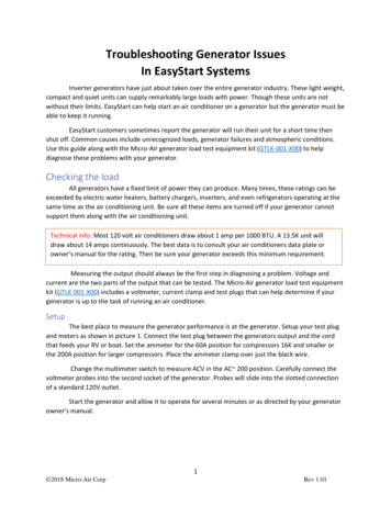
AssemblyInstall the wheel kit as follows:1. Tip generator so that generator rests on frame withengine end up.2. Slide axle (A) through both mounting brackets.3. Slide a wheel (B) over the axle.NOTE: Be sure to install both wheels with the air pressurevalve on the outboard side.4. Place a washer (C) on axle and then place an e-ring (D)in axle groove.Your generator requires some assembly and is ready for useafter it has been properly serviced with the recommendedfuel and oil.If you have any problems with the assembly of your generator,please call the generator helpline at (800) 743-4115. If callingfor assistance, please have the model, revision, and serialnumber from the data tag available. See Controls and Featuresfor data tag location.Unpack GeneratorCAUTION1. Set the carton on a rigid, flat surface.2. Remove everything from carton except generator andconfirm all listed parts are present.3. Open carton completely by cutting each corner fromtop to bottom.4. Leave generator on carton to install wheel kit.E-rings can cause eye injury.E-rings can spring back and become airbornewhen installing or removing. Always wear eye protection when installing/removing e-rings.5. Install e-ring with pliers, squeezing from top of e-ringto bottom of axle.6. Repeat step 3 thru 5 to secure second wheel.7. Tip generator so that generator rests on frame withengine side down.8. Attach the vibration mounts (E) to the support leg (F)with 1/4-20 x 1” capscrews (G) and 1/4-20 lock nuts(H).9. Attach support leg with M8 x 20 mm cap screws (J)and M8 lock nuts (K).10. Return generator to normal operating position (restingon wheels and support leg).11. Check each fastener to ensure it is secure and the tiresare inflated between 15-40 PSI.The generator is supplied with: Operator’s manual Battery float charger Oil bottles Wheel kitInstall Wheel KitNOTE: Wheel kit is not intended for over-the-road use.You will need the following tools to install thesecomponents: 7/16” and 13mm socket wrench 7/16” and 13mm open end wrench Pliers Safety glassesBCAHJFDEGK7
Add Engine Oil1. Place generator on a flat, level surface.2. Clean area around oil fill and remove yellow oil fill cap.NOTE: See Oil in Engine Maintenance to review oilrecommendations. Verify provided oil bottle is correctviscosity for current ambient temperature.3. Using oil funnel (optional), slowly pour contents ofprovided oil bottle into oil fill opening until oil levelreaches the “Full” mark on the dipstick.NOTICEImproper treatment of generator can damage it andshorten its life. DO NOT attempt to crank or start the engine before it has beenproperly serviced with the recommended oil. This may result inan engine failure.4. Replace oil fill cap and fully tighten.Add FuelFuel must meet these requirements: Clean, fresh, unleaded gasoline. A minimum of 87 octane/87 AKI (91 RON). Highaltitude use, see High Altitude. Gasoline with up to 10% ethanol (gasohol) or up to15% MTBE (methyl tertiary butyl ether) is acceptable.WARNINGFuel and its vapors are extremely flammable andexplosive.Fire or explosion can cause severe burns ordeath.WHEN ADDING FUEL Turn generator OFF and let it cool at least 2 minutes beforeremoving fuel cap. Loosen cap slowly to relieve pressure intank. Fill fuel tank outdoors. DO NOT overfill tank. Allow space for fuel expansion. If fuel spills, wait until it evaporates before starting engine. Keep fuel away from sparks, open flames, pilot lights, heat, andother ignition sources. DO NOT light a cigarette or smoke.1. Clean area around fuel fill cap, remove cap.2. Slowly add unleaded gasoline (A) to fuel tank (B). Becareful not to overfill. Allow about 1.5" (4 cm) of tankspace (C) for fuel expansion.BCANOTICEAvoid generator damage.Failure to follow Operator’s Manual for fuelrecommendations voids warranty. DO NOT use unapproved gasoline such as E85 or E22. DO NOT mix oil in gasoline. DO NOT modify engine to run on alternate fuels.To protect the fuel system from gum formation, mix in a fuelstabilizer when adding fuel. See Storage. All fuel is not thesame. If you experience starting or performance problemsafter using fuel, switch to a different fuel provider or changebrands. This engine is certified to operate on gasoline. Theemission control system for this engine is EM (EngineModifications).83. Install fuel cap and let any spilled fuel evaporate beforestarting engine.High AltitudeAt altitudes over 5,000 feet (1524 meters), a minimum85 octane / 85 AKI (89 RON) gasoline is acceptable. Toremain emissions compliant, high altitude adjustment isrequired. Operation without this adjustment will causedecreased performance, increased fuel consumption, andincreased emissions. See an authorized dealer for highaltitude adjustment information. Operation of the engine ataltitudes below 2,500 feet (762 meters) with the high altitudekit is not recommended.BRIGGSandSTRATTON.COM
Attach Negative Battery CableSystem GroundYour unit is equipped with electric start capability but can bestarted manually. If you choose not to use the electric startfeature, you do not need to connect the negative batterycable.The sealed battery on the generator pre–installed except forthe negative (black) battery cable.The generator has a system ground that connects thegenerator frame components to the ground terminals on theAC output receptacles. The system ground is connected tothe AC neutral wire (the neutral is bonded to the generatorframe).To install:1. Cut off tie wrap securing loose end of negative (black)cable.2. Remove screw (A), lock washer (B) and flat washer (C)on negative battery terminal.DSpecial RequirementsThere may be Federal or State Occupational Safety andHealth Administration (OSHA) regulations, local codes, orordinances that apply to the intended use of the generator.Please consult a qualified electrician, electrical inspector, orthe local agency having jurisdiction: In some areas, generators are required to be registeredwith local utility companies. If the generator is used at a construction site, theremay be additional regulations which must be observed.Connecting to a Building’s Electrical SystemACB3. Slide lock washer, flat washer and negative batterycable (D) over screw.4. Reattach screw to negative battery terminal and tighten.5. Verify that connections to battery and generator aretight and secure.NOTE: If your battery is discharged, charge prior to usefollowing the instructions in the section Battery FloatCharger.Connections for standby power to a building’s electricalsystem must be made by a qualified electrician. Theconnection must isolate the generator power from utilitypower or other alternative power sources and must complywith all applicable laws and electrical codes.WARNINGGenerator produces hazardous voltage.Failure to isolate generator from power utility canresult in death or injury to electric utility workersdue to backfeed of electrical energy. When using generator for backup power, notify utility company.Use approved transfer equipment to isolate generator fromelectric utility. Use a ground fault circuit interrupter (GFCI) in any damp orhighly conductive area, such as metal decking or steel work. DO NOT touch bare wires or receptacles. DO NOT use generator with electrical cords which are worn,frayed, bare or otherwise damaged. DO NOT operate generator in the rain or wet weather. DO NOT handle generator or electrical cords while standing inwater, while barefoot, or while hands or feet are wet. DO NOT allow unqualified persons or children to operate orservice generator.9
Generator LocationClearances and Air MovementWARNINGExhaust heat/gases can ignite combustibles,structures or damage fuel tank causing a fire. Keep at least 5 ft. (1.5 m) clearance on all sides of generatorincluding overhead.Place generator outdoors in an area that will not accumulatedeadly exhaust gas. DO NOT place generator where exhaustgas (A) could accumulate and enter inside or be drawn into apotentially occupied building. Ensure exhaust gas is keptaway from any windows, doors, ventilation intakes, or otheropenings that can allow exhaust gas to collect in a confinedarea. Prevailing winds and air currents should be taken intoconsideration when positioning generator.10ABRIGGSandSTRATTON.COM
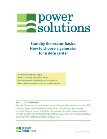
Features and ControlsRead this Operator’s Manual and safety rules before operating your generator.Compare the illustrations with your generator, to familiarize yourself with the locations of various controls andadjustments. Save this manual for future reference.KJHABCDGEFA - 120 Volt AC, 20 Amp, Duplex Receptacles — May beused to supply electrical power for the operation of120 Volt AC, 20 Amp, single phase, 60 Hz electrical,lighting, appliance, tool, and motor loads.B - Circuit Breakers (AC) — The 120 Volt AC, 20A duplexreceptacles are provided with "push to reset" circuitbreakers to protect the generator against electrical overload.C - Double Pole Circuit Breaker (AC) — The 120/240 Volt AC,30A locking receptacle is provided with a double polecircuit breaker to protect the generator against electricaloverload. This switch also controls all receptacles.D - 120/240 Volt AC, 30 Amp Locking Receptacle — Maybe used to supply electrical power for the operation of120 and/or 240 Volt AC, 30 Amp, single phase, 60 Hzelectrical, lighting, appliance, tool and motor loads.E - Grounding Fastener — Consult your local agency havingjurisdiction for grounding requirements in your area.F - Data Tag — Provides model, revision, and serial numberof generator. Please have these readily available whencalling for assistance.G - Spark Arrester Muffler — Exhaust muffler lowers enginenoise and is equipped with a spark arrester screen.H - Air Cleaner — Protects engine by filtering dust anddebris out of intake air.J - Choke Lever — Used when starting a cold engine.K - Fuel Tank — Capacity of seven (7) U.S. gallons (26.5 L).Items Not Shown:Battery Float Charger Jack — Use battery float charger tokeep the starting battery charged and ready for use.Engine Identification — Provides model, type and code ofengine. Please have these readily available if calling forassistance.Engine Rocker Switch — Set this switch to run position (I)before using recoil starter. Set switch to stop position (O) tostop engine.Fuel Valve — Used to turn fuel supply on and off to engine.Oil Drain Plug — Drain engine oil here.Oil Fill Cap/Dipstick — Check and fill engine with oil here.Recoil Starter — Used to start the engine.Start Switch — Push and hold in “Start” position for amaximum of 15 seconds during each start attempt, untilengine starts.11
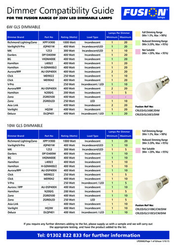
Cord Sets and ReceptaclesUse only high quality, well-insulated, grounded extensioncords with the generator’s 120 Volt duplex receptacle.Inspect extension cords before each use.Check the ratings of all extension cords before you usethem. Extension cord sets used should be rated for 125 VoltAC loads at 20 Amps or greater for most electrical devices.Some devices, however, may not require this type ofextension cord. Check the operator’s manuals of thosedevices for the manufacturer’s recommendations.Keep extension cords as short as possible to minimizevoltage drop.WARNINGOverloaded electrical cords can overheat, arc,and burn resulting in death, bodily injury, and/orproperty damage.This receptacle powers 120/240 Volt AC, 60 Hz, single phaseloads requiring up to 7,200 watts of power (7.2 kW) at30 Amps for 240 Volts or two independent 120 Volt loads at30 Amps each. The outlet is protected by a double polerocker switch circuit breaker.NOTICEReceptacles may be marked with rating value greater thangenerator output capacity. NEVER attempt to power a device requiring more amperagethan generator or receptacle can supply. DO NOT overload the generator. See Don’t Overload Generator.120 Volt AC, 20 Amp, Duplex ReceptaclesEach duplex receptacle is protected against overload by apush-to-reset circuit breaker. ONLY use cords rated for your loads. Follow all safeties on electrical cords.120/240 Volt AC, 30 Amp, Locking ReceptacleUse a NEMA L14-30 plug with this receptacle. Connect a4-wire cord set rated for 250 Volt AC loads at 30 Amps (orgreater). You can use the same 4-wire cord if you plan torun a 120 Volt load.4-Wire Cord Set240V120V120VW (Neutral)Y (Hot)NEMA L14-3012Use each receptacle to operate 120 Volt AC, single-phase,60 Hz electrical loads requiring up to 2,400 watts (2.4 kW) at20 Amps of current. Use cord sets that are rated for 125 VoltAC loads at 20 Amps (or greater). Inspect cord sets beforeeach use.X (Hot)Ground (Green)BRIGGSandSTRATTON.COM
Battery Float ChargerUse battery float charger jack to keep the starting batterycharged and ready for use. Battery charging should be donein a dry location, such as inside a garage.1. Plug charger into unit’s “Battery Float Charger” jack,which is located next to the start switch. Plug batterycharger into a 120 Volt AC wall receptacle.2. Unplug charger from unit and wall outlet whengenerator is being started and while it is in operation.3. Keep this charger plugged in when generator is not inuse to prolong battery life. The charger has a built infloat equalizer and will not overcharge the battery, evenwhen plugged in for an extended period of time.IMPORTANT: See Battery Maintenance for additionalinformation.13
OperationStarting the EngineIMPORTANT: Always unplug the battery float charger beforestarting the generator.Disconnect all electrical loads from the generator. Use thefollowing start instructions:1. Make sure unit is on a level surface.IMPORTANT: Failure to start and operate the unit on a levelsurface will cause the unit not to start or shut down duringoperation.2. Turn the fuel valve to the “On” position. The fuel valvehandle should be vertical (pointing toward the ground)for fuel to flow.3. Push engine rocker switch to run position (I).NOTE: If battery is discharged, use manual startinginstructions.5B. For manual starting, grasp recoil handle and pullslowly until slight resistance is felt. Then pull rapidlyone time only to start engine.WARNINGStarter cord kickback (rapid retraction) can resultin bodily injury. Kickback will pull hand and armtoward engine faster than you can let go.Broken bones, fractures, bruises, or sprainscould result. When starting engine, pull cord slowly until resistance is felt andthen pull rapidly to avoid kickback. NEVER start or stop engine with electrical devices plugged inand turned on. If engine starts, proceed to step 7. If engine fails to start, proceed to step 6.6. Move choke lever to “Half” choke position, and pullrecoil handle twice. If engine fails to start, repeat steps 5 thru 7.7. Slowly move choke lever to “Run” position. If enginefalters, move choke lever to “Half” choke position untilengine runs smoothly, and then to “Run” position.IMPORTANT: If engine floods, place choke lever in “Run”position and crank until engine starts.WARNING4. Push choke lever to “Choke” position.Contact with muffler area can result in seriousburns.Exhaust heat/gases can ignite combustibles,structures or damage fuel tank causing a fire.5A. For electric starting, push and hold the start switch in“Start” position until generator starts. To prolong thelife of starter components, DO NOT hold start switch in“Start” position for more than 15 seconds, and pausefor at least 1 minute between starting attempts. 14 DO NOT touch hot parts and AVOID hot exhaust gases. Allow equipment to cool before touching. Keep at least 5 feet (1.5 m) of clearance on all sides ofgenerator including overhead. Code of Federal Regulation (CFR) Title 36 Parks, Forests, andPublic Property require equipment powered by an internalcombustion engine to have a spark arrester, maintained ineffective working order, complying to USDA Forest servicestandard 5100-1C or later revi
Transport/repair with fuel tank EMPTY or with fuel shutoff valve OFF. Disconnect spark plug wire. WHEN STORING FUEL OR EQUIPMENT WITH FUEL IN TANK Store away from furnaces, stoves, water heaters, clothes dryers, or other appliances that have pilot light or other ignition source because they can ignite fuel vapors. WARNING