Transcription
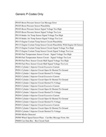
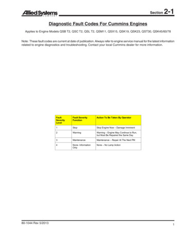
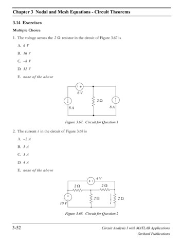
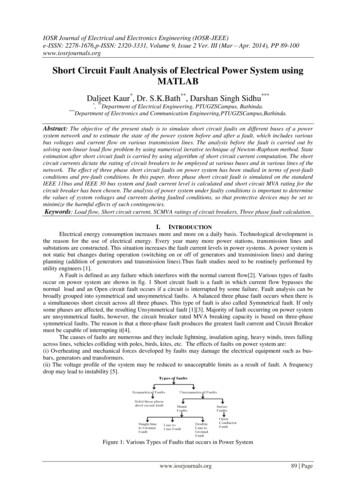
IOSR Journal of Electrical and Electronics Engineering (IOSR-JEEE)e-ISSN: 2278-1676,p-ISSN: 2320-3331, Volume 9, Issue 2 Ver. III (Mar – Apr. 2014), PP 89-100www.iosrjournals.orgShort Circuit Fault Analysis of Electrical Power System usingMATLABDaljeet Kaur*, Dr. S.K.Bath**, Darshan Singh Sidhu**** *****, Department of Electrical Engineering, PTUGZSCampus, Bathinda.Department of Electronics and Communication Engineering,PTUGZSCampus,Bathinda.Abstract: The objective of the present study is to simulate short circuit faults on different buses of a powersystem network and to estimate the state of the power system before and after a fault, which includes variousbus voltages and current flow on various transmission lines. The analysis before the fault is carried out bysolving non-linear load flow problem by using numerical iterative technique of Newton-Raphson method. Stateestimation after short circuit fault is carried by using algorithm of short circuit current computation. The shortcircuit currents dictate the rating of circuit breakers to be employed at various buses and in various lines of thenetwork. The effect of three phase short circuit faults on power system has been studied in terms of post-faultconditions and pre-fault conditions. In this paper, three phase short circuit fault is simulated on the standardIEEE 11bus and IEEE 30 bus system and fault current level is calculated and short circuit MVA rating for thecircuit breaker has been chosen. The analysis of power system under faulty conditions is important to determinethe values of system voltages and currents during faulted conditions, so that protective devices may be set tominimize the harmful effects of such contingencies.Keywords: Load flow, Short circuit current, SCMVA ratings of circuit breakers, Three phase fault calculation.I.INTRODUCTIONElectrical energy consumption increases more and more on a daily basis. Technological development isthe reason for the use of electrical energy. Every year many more power stations, transmission lines andsubstations are constructed. This situation increases the fault current levels in power systems. A power system isnot static but changes during operation (switching on or off of generators and transmission lines) and duringplanning (addition of generators and transmission lines).Thus fault studies need to be routinely performed byutility engineers [1].A Fault is defined as any failure which interferes with the normal current flow[2]. Various types of faultsoccur on power system are shown in fig. 1 Short circuit fault is a fault in which current flow bypasses thenormal load and an Open circuit fault occurs if a circuit is interrupted by some failure. Fault analysis can bebroadly grouped into symmetrical and unsymmetrical faults. A balanced three phase fault occurs when there isa simultaneous short circuit across all three phases. This type of fault is also called Symmetrical fault. If onlysome phases are affected, the resulting Unsymmetrical fault [1][3]. Majority of fault occurring on power systemare unsymmetrical faults, however, the circuit breaker rated MVA breaking capacity is based on three-phasesymmetrical faults. The reason is that a three-phase fault produces the greatest fault current and Circuit Breakermust be capable of interrupting it[4].The causes of faults are numerous and they include lightning, insulation aging, heavy winds, trees fallingacross lines, vehicles colliding with poles, birds, kites, etc. The effects of faults on power system are:(i) Overheating and mechanical forces developed by faults may damage the electrical equipment such as busbars, generators and transformers.(ii) The voltage profile of the system may be reduced to unacceptable limits as a result of fault. A frequencydrop may lead to instability [5].Figure 1: Various Types of Faults that occurs in Power Systemwww.iosrjournals.org89 Page
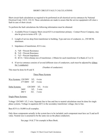
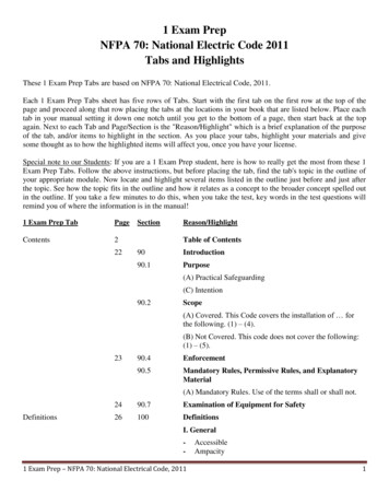
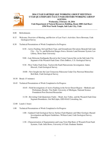
Short Circuit Fault Analysis of Electrical Power System using MATLAB1.1 USE OF SIMULATION SOFTWAREIn this paper, short circuit fault analysis on power system is done by using MATLAB programming.MATLAB is a powerful software package used for high performance scientific numerical computation, dataanalysis and visualization.The single line diagram for standard IEEE 11 bus and IEEE 30 bus system is shown in Fig. 2 and Fig.3.Figure2: One line diagram for 11 bus systemFigure3: One line diagram for IEEE 30 bussystem1.2NEED FOR FAULT ANALYSIS IN PLANNING AND OPERATION OF POWER SYSTEMThe system being planned is to be optimal with respect to construction cost, performance and operatingefficiency. For this better planning tools are required. In general, the major power system tools are: load FlowAnalysis, short circuit analysis or fault calculations, stability analysis etc.The purpose of an electrical power system is to generate and supply electrical energy to consumers withreliability and economy. The greatest threat to this purpose of a power system is the short circuit [3]. Theevaluation of fault currents on a power system is significant because the protective devices to be installed on thesystem depend on the values of the fault currents. Information gained from fault analysis used to select theappropriate size and type of protective equipments to be installed on the system so that the continuity of supplyis ensured even when there is a fault on the power system.II.Short Circuit Fault Analysis Problem Formulation2.1 PRELIMINARY CALCULATIONSIn the fault studies, it is necessary to have the knowledge of pre-fault voltages and currents. These prefault conditions can be obtained from the results of load flow studies by the Newton Raphson method. Loadflow analysis is a technique that provides basic calculation procedure in order to determine the characteristics ofpower system under steady state condition [8]. A solution of the power flow problem using Newton Raphsonmethod is depicted in Fig. 4. The Newton Raphson method is adopted for large networks due to its quadraticconvergence characteristics, high accuracies obtained in a few iterations and no. of iterations independent of thesize of the system [4].Figure 4: Flow Chart for Newton Raphson Load Flow Methodwww.iosrjournals.org90 Page
Short Circuit Fault Analysis of Electrical Power System using MATLAB2.2 CALCULATION OF SHORT CIRCUIT CURRENTSIf the insulation of system fails at any point or if two or more conductor that normally operates with apotential difference comes in contact with each other , a short circuit is said to be occur. Fault analysis calculatethe fault currents magnitudes that are used to determine short circuit megavolt ampere(SCMVA) ratings ofappropriate circuit breakers[9][10]. For a symmetrical fault, the negative and zero sequences are absent. Thepositive sequence present and modified for fault analysis as shown in Fig.5:Figure 5: Positive Sequence Network Modified for Fault Analysis[11]The injected bus currents in terms of bus voltages for a n-bus network is calculated as;Ibus Ybus .Vbus(1)Where Ibus is the bus current vector entering the bus & Ybus is the bus admittance matrixFor a fault at bus k, the current entering every bus except the faulted bus k is zero thus equation (1) becomes: (2)]] [[] [Equation (2) can be written asIbus(F) Ybus .ΔVbusFrom above equation ;Δ Vbus inverse(Ybus). Ibus(F) Zbus . Ibus(F)Zbus inverse(Ybus) is the bus impedance matrixVbus(F) Vbus(0) ΔVbusSubstituting (4) into equation (5) gives;V(F) Vbus(0) Zbus.Ibus(F)Above equation (6) can be written in matrix form as; (3)(4)(5)(6) [] [][] []The voltage at bus k during the fault is Vk(F). So;Vk(f) Vk(0) – Zkk. Ik(F)(7)But Vk(F) Zf.Ik(F), where Zf is fault impedance & Where Zkk is kth kth element of bus impedance matrix andthis equation put in above equation (7)Equation (7) becomes;Zf.Ik(F) Vk(0) – Zkk. Ik(F)Solving for Ik(F) gives;Ik(F) (8)fFor bolted or solid fault , Z 0 [12]For any bus i the bus voltage during fault is;Vi(F) Vi(0) – Zik . Ik(F) , where Zik is ith kth element of bus impedance matrix.From equation(8) ;Vi(F) Vi(0) – Zik .(9)The short circuit current in the line connected between bus i and j is;Iij(F) –where zij is series impedance when line connected between buses i and j.(10)Flow Chart for the Calculations of Three-Phase Short Circuit Fault is shown in figure 6.www.iosrjournals.org91 Page
Short Circuit Fault Analysis of Electrical Power System using MATLABFigure 6: Flow Chart for the Calculations of Three-Phase Short Circuit Fault.2.3 SELECTION OF CIRCUIT BREAKERSThe circuit breaker has to perform the following major duties under short circuit conditions;1) To open the contacts to clear the fault.2) To close the contacts onto a fault.3) To carry fault current for a short time while another circuit breaker is clearing the fault.In addition to the rated voltage, current and frequency, circuit breakers have the following important ratings:1) Breaking capacity 2) Making capacity 3) Short time capacityThe Breaking capacity of a circuit breaker is of two types i.e. Symmetrical Breaking capacity and AsymmetricalBreaking capacity.Symmetrical breaking capacity: It is the r.m.s value of the ac component of the fault current that the circuitbreaker is capable of breaking under specified conditions of recovery voltage.Asymmetrical breaking capacity: It is the r.m.s value of the total current comprising of both ac and dccomponents of the fault current that the CB can break under specified conditions of recovery voltage.The breaking capacity of a CB is generally expressed in MVA.If voltage & current in p.u. values on a 3ph. Basis,thenSCMVA(3 ph) Vprefault * Isc *(MVA base)(11)Rated MVA interrupting capacity of a CB is to be more than or equal to the short circuit MVA required to beinterrupted[4].The rated asymmetrical breaking capacity is 1.6 times the rated symmetrical current.Making capacity: The rated making current is defined as the peak value of the current including dc componentin the first cycle at which a CB can be closed onto a short circuit.Making current 2 * 1.8 * symmetrical breaking currentThe multiplication byis obtain the peak value and again by 1.8 to take the d.c. component into account.Short -time current rating : It is the r.m.s value of total current that the CB can carry safely for a specified shortperiod.Short time current rating Breaking current / rated normal current[13].2.4 A COMPUTATIONAL ALGORITHM FOR SHORT CIRCUIT STUDIESAlgorithm adopted for this type of analysis consists following steps;STEP 1: Obtain pre-fault voltages at all buses and currents in all lines through a load flow study.STEP 2: Find Bus impedance matrix by inverting the bus admittance matrix.STEP 3: Choose MVAbase, KVbase & calculate Ibase.STEP 4: Specify the faulty bus and obtain current at the faulty bus using equation (8) and bus voltages duringfault at all buses using equation (9).STEP 5: Find current flows in each line of the system using equation (10).STEP 6: Calculate SCMVA rating of circuit breaker(choose acc. to the fault current magnitude ) for each line &at each bus using equation (11).www.iosrjournals.org92 Page
Short Circuit Fault Analysis of Electrical Power System using MATLABIII.Results And Discussion3.1 RESULTS FOR IEEE 11 BUS 17 TRANSMISSION LINE SYSTEMFirstly, discuss the results for load flow for IEEE 11 bus system. The load flow analysis was carriedout using the Newton-Raphson load flow method. This analysis determines the voltage magnitude, phase anglein degree, real power and reactive powers at each bus and current flows in the transmission lines. The result ofthe load flow is shown in Table 1 and Table 2. It can be observed that the voltage magnitudes are within thetolerance ranges of 10%.Table 1: Voltage magnitude , phase Angle, Real and Reactive Powers from pre-fault analysis by NewtonRaphson Method on Standard IEEE 11 bus system.Bus no.1234567891011Voltage 1.01180.98900.99831.03261.0310Voltage .306866.778365.272365.887668.151768.0450Angle 9-3.3570-1.5303-1.9984-2.4009Real 4000-0.9000-0.7000-0.2500-0.2500Reactive .1000-0.4500-0.3500-0.0500-0.0500Table 2: Line current magnitudes from load flow analysis using Newton Raphson Method on IEEE 11 bussystem.Line no.1234567891011121314151617From bus – To 108-1110-11CurrentMagnitude 60.0012Current Magnitude 86.63741.0890After the pre-fault calculations, a three phase short circuit fault was simulated on the 11 bus system thencalculated the total fault current at each bus, fault voltage magnitude at each bus, fault voltage phase angle ateach bus, fault current flows in the lines, SCMVA ratings based on the fault currents on each bus and lines wasalso calculated then the corresponding Circuit Breakers ratings are choosed. Total fault current at each bus andSCMVA ratings for that fault currents on each bus is shown in Table 3. The range of the circuit breakers at eachbus determined for the 11 bus system is within 35MVA and 45MVA.Table 3: Fault current magnitude, Short circuit MVA and Circuit breaker ratings at each bus.Fault at erRating (MVA)4545454040403535354040Compare the pre-fault voltage magnitude in p.u. and fault voltage magnitude at each bus and it is observed thatwhen a short circuit occurs, the voltage at faulted bus is reduced to zero and voltage magnitude on other buseswww.iosrjournals.org93 Page
Short Circuit Fault Analysis of Electrical Power System using MATLABare also effected, shown in Table 4 and also compare the pre-fault voltage angle in degree with the post-faultangle at each bus. It is seen that voltage angle at each bus increases when fault occur at different buses as shownin Table5.Table 4: Effect on voltage magnitude in p.u after short circuit occurs at different 5303-1.9984-2.4009Whenfault atbus 3700.10620.0756Whenfault atbus 5320.08620.1078Whenfault atbus 7820.13970.1492Whenfault atbus 9610.07100.0744Whenfault atbus 8710.09420.0910Whenfault atbus 2150.11160.1120Whenfault atbus 6030.00710.0183Whenfault atbus 1430.03220.0287Whenfault atbus 7200.01670.0131Whenfault 690.06800.076500.0274Whenfault 140.08100.08150.03710Table 5: Effect on voltage angle in degree after short circuit occurs at different buses.Whenfault atbus .98167.67171.14Whenfault atbus .60174.21171.74Whenfault atbus .09169.35168.90Whenfault atbus 0173.49168.67168.69Whenfault atbus .32163.53164.05Whenfault atbus .19162.78163.08Whenfault atbus 189.66141.04Whenfault atbus 9.816Whenfault atbus 09-90.00120.80110.24Whenfault 73.20169.5090.00162.13Whenfault 70.44168.38159.640Table 6: Effect of three phase short circuit fault on line current magnitudes in p.u.Lineno.PreFaultcurrent(p.u)Whenfault atbus no.1Whenfault atbus no.2Whenfault atbus no.3Whenfault atbus no.4Whenfault atbus no.5Whenfault atbus no.6Whenfault atbus no.7Whenfault atbus no.8Whenfault atbus no.9Whenfault atbusno.10Whenfault 7260.0977www.iosrjournals.org94 Page
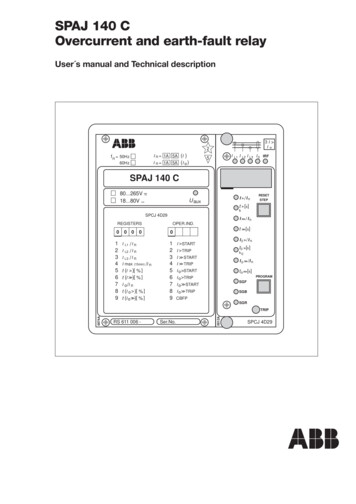
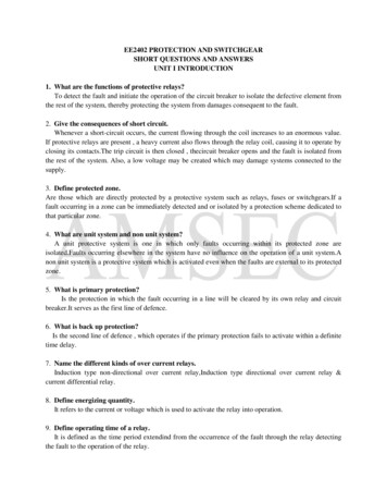
Short Circuit Fault Analysis of Electrical Power System using MATLABcurrentflow in each line0.7fault at bus1fault at bus2fault at bus3fault at bus4fault at bus5fault at bus6fault at bus7fault at bus8fault at bus9fault at bus10fault at line no.Figure 7: Graphical Representation of line currents when fault occur at different buses.From the Table 6, it is analyzed that in line no. 1 maximum fault current flowing upto 0.2624 p.u. when thereis a fault at bus no.1 & line no. 2 is most effected when there is a fault at bus no.1.& line no.3 is most effectedwhen there is a fault at bus no.3.& similarly check other lines and this effect is clearly shown from graphicalrepresentation of current flow in each line when short circuit fault occurs at different buses as shown in Fig.7Now choose the SCMVA rating of Circuit Breaker for each line according to the Table 6.Table7: SCMVA and Circuit Breaker Ratings in each line of the Standard 11 bus 9.8914.7612.3126.5726.9510.08CircuitBreakerrating (MVA)30502050604020402020603020203030203.2 RESULTS FOR IEEE 30 BUS 41 TRANSMISSION LINE SYSTEMThe load flow analysis was carried out using the Newton-Raphson load flow method then after the prefault calculations, a three phase short circuit fault was simulated on bus no.1,2,3,4,13,15,16,28,30 of the IEEE30 bus system then calculated the fault voltage magnitude at each bus, fault voltage angle at each bus, faultcurrents flows in the lines, total fault current at each bus, SCMVA ratings based on the fault currents on eachbus and line then the corresponding Circuit Breakers ratings are choosed. Compare the pre-fault results withpost-fault results and all these results are shown below.Table 8: Effect on voltage magnitude in p.u after short circuit occurs at buses .9989WhenFault atbus ult atbus ult atbus ult atbus ult atbus www.iosrjournals.orgWhenFault atbus WhenFault atbus WhenFault atbus WhenFault atbus 95 Page
Short Circuit Fault Analysis of Electrical Power System using 8820.10180.09790.11670.08640.05970.10730.1195Table 9: Effect on voltage 187 7.5981 ult atbus 49177.1925176.2688177.6534177.8578WhenFault atbus 20.18340.19900.14420.22260.07910in degree after short circuit occurs at buses 1,2,3,4,13,15,16,28,30.WhenFault atbus .8572174.6060177.6589177.9611WhenFault atbus 2175.6829178.6657178.8709WhenFault atbus 086176.0698176.9310176.4669176.6629WhenFault atbus 163.2939162.1233166.8935168.3605WhenFault atbus 84165.8686165.5754168.1365169.1519WhenFault atbus .8123-179.6780-179.805-179.841WhenFault atbus 42147.8607138.2480146.8265140.72090Table 10: Effect of three phase short circuit fault on line current magnitudes in 090.01340.01680.00090.00340.0005WhenFaultat 690.0628WhenFaultat 570.0539WhenFaultat 820.0921WhenFaultat 300.0977WhenFaultat 7300.1100www.iosrjournals.orgWhenFaultat 7470.1073WhenFaultat 7340.1093WhenFaultat 6900.1136WhenFaultat 6810.119496 Page
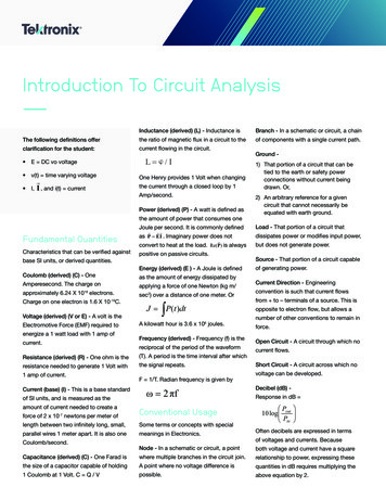
Short Circuit Fault Analysis of Electrical Power System using 18380.22460.13870.21120.15430.04970.1505From table 10, Comparing the line flow currents during fault with the pre-fault line flow currents; it is analyzethat line currents increases from their normal value when there is a fault at different buses. Above table alsoshows that how much fault current flows in each line when there is a fault at different buses. From Table 10, inline no. 1 maximum current flowing when there is a fault occur at bus no.1 i.e 0.4006 p.u & in line no. 2maximum current flowing when there is a fault at bus no.1.& in line no.3 maximum current flowing during faultat bus no.2 & in line no. 4 maximum current flowing when there is a fault at bus no.3 & similarly check otherlines for fault at each bus of the system and choose the SCMVA rating of CB for each line acc. to above table.This effect is cleared by a graph that showing the current flow in line no.1 when fault occur at different buses, asshown in fig.8.From Table 11&12, it is to be noted that in the lines of IEEE 30bus 330KV system , circuit breaker ratingsranges between 10 MVA to 70 MVA. The operating personnel can use the relay settings according to the faultcurrent magnitude & circuit breaker ratings.currentflow in line no. 1 when fault occur at different 5101520no. of buses253035Figure 8: Graphical Representation for Current flow in line no.1 when there is a fault occur at each bus of Ieee30 bus system.www.iosrjournals.org97 Page
Short Circuit Fault Analysis of Electrical Power System using MATLABTable11&12 SCMVA and Circuit Breaker Ratings in each line of the Ieee 30 bus system.Line 163.5837.7825.2767.0820.8925.2217.7814.0933.55CB ine .6221.0438.5218.2222.3825.6220.4914.645.91917.78CB le 13&14: Tot
Analysis, short circuit analysis or fault calculations, stability analysis etc. The purpose of an electrical power system is to generate and supply electrical energy to consumers with reliability and economy. The greatest threat to this purpose of a power system is the short circuit [3]. The