Transcription
Amphenol 97 SeriesStandard Cylindrical Connector12-022-15MIL-5015 Style Connectorswidely used for: Factory Automation, RoboticsMachine Tool, InstrumentationWelding EquipmentMedical EquipmentAmphenol 97 Series Connectors areUL recognized and CSA recognized.Amphenol
Table of ContentsPageAmphenol 97 Series Standard Cylindrical Connectors – General Description . . . . . . . . . . . . . . . . . . . . . . . . . . . . . . . . . . . . . 1Guide to Selecting a Connector . . . . . . . . . . . . . . . . . . . . . . . . . . . . . . . . . . . . . . . . . . . . . . . . . . . . . . . . . . . . . . . . . . . . . . . . . 2Amphenol 97 Series Connectors with Solder ContactsDesign Characteristics, Customer Options . . . . . . . . . . . . . . . . . . . . . . . . . . . . . . . . . . . . . . . . . . . . . . . . . . . . . . . . . . . . . 3Insert Availability . . . . . . . . . . . . . . . . . . . . . . . . . . . . . . . . . . . . . . . . . . . . . . . . . . . . . . . . . . . . . . . . . . . . . . . . . . . . . . . 4, 5Contact Arrangements . . . . . . . . . . . . . . . . . . . . . . . . . . . . . . . . . . . . . . . . . . . . . . . . . . . . . . . . . . . . . . . . . . . . . . . . . . 6-11Alternate Insert Positioning . . . . . . . . . . . . . . . . . . . . . . . . . . . . . . . . . . . . . . . . . . . . . . . . . . . . . . . . . . . . . . . . . . . . . . . . 12Receptacle Shell Styles . . . . . . . . . . . . . . . . . . . . . . . . . . . . . . . . . . . . . . . . . . . . . . . . . . . . . . . . . . . . . . . . . . . . . . . . . . 13Solid Shell Plug Styles . . . . . . . . . . . . . . . . . . . . . . . . . . . . . . . . . . . . . . . . . . . . . . . . . . . . . . . . . . . . . . . . . . . . . . . . . . . 14Split Shell Plug Styles . . . . . . . . . . . . . . . . . . . . . . . . . . . . . . . . . . . . . . . . . . . . . . . . . . . . . . . . . . . . . . . . . . . . . . . . . . . . 15Weight Reference Charts . . . . . . . . . . . . . . . . . . . . . . . . . . . . . . . . . . . . . . . . . . . . . . . . . . . . . . . . . . . . . . . . . . . . . . . 16-18How to Order. . . . . . . . . . . . . . . . . . . . . . . . . . . . . . . . . . . . . . . . . . . . . . . . . . . . . . . . . . . . . . . . . . . . . . . . . . . . . . . . . . . 19Amphenol 97 Series Connectors with Rear Release Crimp ContactsDesign Characteristics, Customer Options . . . . . . . . . . . . . . . . . . . . . . . . . . . . . . . . . . . . . . . . . . . . . . . . . . . . . . . . . . . . 20Specifications and Insert Availability, Alternate Insert Positioning . . . . . . . . . . . . . . . . . . . . . . . . . . . . . . . . . . . . . . . . . . 21Contact Arrangements . . . . . . . . . . . . . . . . . . . . . . . . . . . . . . . . . . . . . . . . . . . . . . . . . . . . . . . . . . . . . . . . . . . . . . . . 22, 23Receptacle Shell Styles . . . . . . . . . . . . . . . . . . . . . . . . . . . . . . . . . . . . . . . . . . . . . . . . . . . . . . . . . . . . . . . . . . . . . . . . . . 24Solid Shell Plug Styles . . . . . . . . . . . . . . . . . . . . . . . . . . . . . . . . . . . . . . . . . . . . . . . . . . . . . . . . . . . . . . . . . . . . . . . . . . . 25Split Shell Plug Styles . . . . . . . . . . . . . . . . . . . . . . . . . . . . . . . . . . . . . . . . . . . . . . . . . . . . . . . . . . . . . . . . . . . . . . . . . . . . 26How to Order. . . . . . . . . . . . . . . . . . . . . . . . . . . . . . . . . . . . . . . . . . . . . . . . . . . . . . . . . . . . . . . . . . . . . . . . . . . . . . . . . . . 27Crimp Contact Information . . . . . . . . . . . . . . . . . . . . . . . . . . . . . . . . . . . . . . . . . . . . . . . . . . . . . . . . . . . . . . . . . . . . . . . . 28Crimp Contact Information cont., Tools. . . . . . . . . . . . . . . . . . . . . . . . . . . . . . . . . . . . . . . . . . . . . . . . . . . . . . . . . . . . . . . 29Special Purpose ConnectorsPotting Construction . . . . . . . . . . . . . . . . . . . . . . . . . . . . . . . . . . . . . . . . . . . . . . . . . . . . . . . . . . . . . . . . . . . . . . . . . . . . . 30Box Type Plugs, Small Flange Receptacles . . . . . . . . . . . . . . . . . . . . . . . . . . . . . . . . . . . . . . . . . . . . . . . . . . . . . . . . . . . 31ECG Connector, Convenience Outlets . . . . . . . . . . . . . . . . . . . . . . . . . . . . . . . . . . . . . . . . . . . . . . . . . . . . . . . . . . . . . . . 3297 Series AccessoriesCable Clamps, Bushing. . . . . . . . . . . . . . . . . . . . . . . . . . . . . . . . . . . . . . . . . . . . . . . . . . . . . . . . . . . . . . . . . . . . . . . . . 33,34Protection Caps . . . . . . . . . . . . . . . . . . . . . . . . . . . . . . . . . . . . . . . . . . . . . . . . . . . . . . . . . . . . . . . . . . . . . . . . . . . . . 35, 36Adapters . . . . . . . . . . . . . . . . . . . . . . . . . . . . . . . . . . . . . . . . . . . . . . . . . . . . . . . . . . . . . . . . . . . . . . . . . . . . . . . . . . . . . . 37Conduit Box Connector, Conduit Coupling Nuts, . . . . . . . . . . . . . . . . . . . . . . . . . . . . . . . . . . . . . . . . . . . . . . . . . . . . . . . 38Sealing Gaskets . . . . . . . . . . . . . . . . . . . . . . . . . . . . . . . . . . . . . . . . . . . . . . . . . . . . . . . . . . . . . . . . . . . . . . . . . . . . . . . . 39Dummy Receptacles . . . . . . . . . . . . . . . . . . . . . . . . . . . . . . . . . . . . . . . . . . . . . . . . . . . . . . . . . . . . . . . . . . . . . . . . . . . . . 40Additional Products . . . . . . . . . . . . . . . . . . . . . . . . . . . . . . . . . . . . . . . . . . . . . . . . . . . . . . . . . . . . . . . . . . . . . . . . . . . . . . 41, 42Sales Office ListingAmphenol Aerospace operates Quality Systems that are Certified to ISO-9001 and AS-9100 by third partyRegistrars.
Amphenol 97 Series Connectorsprovide the interconnection solution for low cost,general duty applicationsAmphenol offers the 97 Series Connector Family A general duty standard cylindrical connector,MIL-5015 style.The 97 Series is a widely used connector series for the automotive, robotics, machine tool and welding industries, as wellas numerous other commercial applications from heavy equipment to ECG monitoring cables.Shell components are fabricated from high grade aluminumalloy to provide strength and environmental protection. Thisfamily of connectors offers a wide variety of shell styles, contact patterns and accessory options.The Amphenol 97 Seriesdesign features and benefits: Low cost, general dutynon-environmental Environmental capability withthe 417 suffix plus 9767 cableclamp (see page 34) Solder or crimp termination UL Recognized, CSA Recognized Wide selection of shell styles and insert patterns Wide selection of connector finishes cadmium or non-cadmium (environmentally friendly zinc alloy) Threaded coupling, hard dielectric inserts Solid or split shell construction Accessories for both individual wire seal and jacketed cableRoHS COMPLIANT PRODUCTAVAILABLE – ConsultAmphenol Industrial Operations.phenolAmEUCHSRoE/2002 / 95 /For additional information on Amphenol 97 Series connectors, or for special applicationrequirements, contact your local Amphenol sales office, authorized distributor, or Amphenol CorporationAmphenol Industrial Operations40-60 Delaware AvenueSidney, New York 13838-1395Telephone: 607-563-5011Fax: 607-563-5157Web site: www.amphenol-industrial.com1
Guide to Selecting a ConnectorIn selecting a connector, it first must bedetermined if a non-environmental 97A or B Series 5015 type is required or ifan environmental MS-5015 Class E, F,or R type* is required.If determined that the general duty,non-environmental 97 series is thechoice - then this catalog is appropriateto your needsThe following 8 steps apply to formulation of a part number.**1How many wires are yougoing to connect?What gauge?These two questions are important,because they indicate which insert youneed. There are literally hundreds tochoose from.The insert arrangements for soldercontact connectors are illustrated onpages 6-11. The inserts most oftenused are highlighted on these pages.Here’s an example of how to choosean insert arrangement. Say you want toconnect eight 16-ga. wires, - first findthe section of arrangements containing 8 contacts. Insert number 20-7 isthe one you want because it containseight 16-ga. contacts and it is one ofthe most often used. The one youchoose might depend on your space orvoltage requirements. The voltagecapacity of each insert is listed underits diagram.If you have more than one wire sizeto connect, the method is essentiallythe same. Actually, the insert configurations for multiple-size wires are a lotmore flexible than they appear. That’sbecause you can always solder asmaller wire to a larger contact. However, soldering a large wire to a smallcontact isn’t recommended because ofsize and current requirements.2What if several identicalconnectors have differentfunctions?Here’s a situation to watch out for. Youhave four identical receptacles on apanel. One carries high current loads.The others have low current functions.A plug mated with the wrong receptacle(cross-mating) could ruin your valuable equipment.To avoid cross-mating, you canorder identical inserts positioned inboth the plugs and receptacles at various angles from standard. These variations from standard position are calledalternate insert positions, and aredescribed on page 12.3What kind of receptacle doyou need?For Wall Mounting Use a wall receptacle, type 3100. The elongated back ofthis receptacle extends through thickwall material. It is threaded to acceptstandard hardware fittings.For Unmounted Applications Usethe cable receptacle, type 3101.For Box or Panel Mounting Use thebox receptacle, type 3102. This receptacle’s back is short to conserve space.It is not threaded on the back end andis used when no accessories such asclamps are needed.4What kind of plug do youneed?For ordinary situations The straightplug, type 3106 meets most connectorrequirements. However . . .when space is critical you may wantto consider using an angle plug, type3108. This type plug lets the cableenter your equipment at a right angle.5Do you need a plug with aSolid or Split back shell?You can get both straight and angleplugs in solid or split back shelldesigns. With the solid shell you havegreater strength and you save space.On the other hand, the split shelldesign lets you quickly inspect the solder terminals when you need to. Thisfeature could be important if you’ll besubjecting the connector to rough handling and heavy use.The designation to use for solidshell construction is the letter A. Thisdesignation letter goes immediately* If an environmental type MIL-5015 E, F or R Class is required, then thecatalog that should be consulted is 12-020, MS/Standard MIL-5015Cylindrical Connectors. See www.amphenol-industrial.com for on-linecatalogs or contact Amphenol, Sidney, NY.2after the main shell type number: forexample, 3106A or 3108A.The designation for split shell construction is the letter B; for example, 3106Bor 3108B.Because of application, receptaclesare made in solid backshell construction only. Their designation is 3100A,3101A. (See how to order for soldercontact connectors, page 19.6Which connector gets thesocket? - the receptacle orthe plug?You’re at the point where you designate which inserts are used with whichshells. Either pin or socket inserts canbe used with plugs or receptacles.Here’s a good rule of thumb. Orderthe sockets for the connector at the“hot” side of the circuit. By having sockets at the power source, there’s littlechance that a wayward finger or screwdriver will short the circuit or cause personal injury.The designation for sockets is simply S in a part number, following theinsert code number. For pins, the designation is P. Therefore, the 20-7Pinsert would have pin contacts, whilethe 20-7S insert would have socketcontacts.7What type of plating is preferred?If you prefer the standard olive cadmium, non-reflective, electrically conductive finish, then no suffix number isrequired. Other plating variations areavailable, including environmentallyfriendly zinc alloy. See how to orderinstructions for the various plating finishes offered for 97 Series solder connectors on page 19.8Do you need anyaccessories?Accessories - cable clamps, protectioncaps and chains, conduit adapters, andpanel gaskets are shown on pages 3339.** These steps are for solder type connectors which are described indetail on pages 3-19. If a crimp type connector is needed, the samesteps apply, however, you should consult pages 20-29 for details on 97Series connectors with crimp contacts.
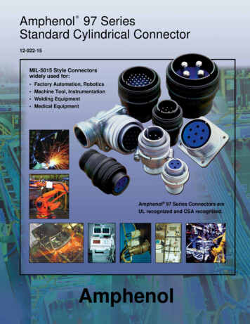
Amphenol 97 Series Connectorswith solder contactsDESIGN CHARACTERISTICS Medium to heavy weight cylindrical Durable, field-proven design Single key/keyway polarization Threaded coupling, hard dielectric inserts Non-rotating contacts Operating temperatures from –55 C to 125 C Cost effective Intermateable and intermountable with existing97 Series and MIL-5015 connectorsMS3100AMS3107A Underwriters Laboratories approved recognition File E115497 Canadian Standards Association CertificationFile LR69183CUSTOMER OPTIONSMS3101A Solid or split shell construction Six shell styles 128 contact arrangements, from 1 to 52 circuits Alternate insert positioning High temperature and potting constructionsMS3107B Special plating finishes including black andgreen zinc alloy Optional gold plating on MS contacts Thermocouple arrangements availableMS3102AConnector components are fabricated from high gradealuminum alloy, with a conductive cadmium plate finishand an olive drab chromate after-treatment. Some cableclamps are a zinc alloy with an olive drab/green chromatefinish. See how to order page 19 for other finish variations.MS3108AContacts are silver plated with pre-tinned solder cups.Optional gold over silver plating is also available. Insertsfor solder style contacts are diallyl-phthalate.MS3106AUsers should be aware that classes “A” and “B” of MIL5015 have been cancelled, and these products are nolonger qualified.MS3108BMS3106B3
97 series solder typeinsert availabilityInsert eRatingContact Size04812Insert iceRatingContact Size04812168S-1 ��31/83.18D310SL-421/161.57A21/83.18D412SL-844 *41/161.57A41/161.57A12S-321/161.57A212-5 11/83.18D12S-6 -1451/161.57A6JGTOQ †314S-2414S-4 16S-171/161.57A720-2716S-4 /161.57A16S-6 161.57A322-8†16-11 1/46.35B6JGTOQ 1818-441/83.18A1AA4INST.2D418-5 .92C18-19†101/161.5718-2051/1618-22†31/818-29 3.18D11/161.57A794Not all insert arrangements are currently available for environmental individualwire seal. Consult Amphenol, Sidney, NY for availability.† Inactive for new military design, but available for replacement or for non-military purposes.* “MS” number not assigned. Use “97” prefix in place of “MS” in completing catalog number. See how to order, page 19.** Hi-Voltage 17KVAC/24KVDC Molded-in pin (MIP) insert requires (910) deviation. See how to order, pg. 19.13.1822-144*K 8QNV CIG1/856D18-818-9 22-13†434
97 series solder typeinsert availability, cingInchesmm1/83.181/83.18ServiceRatingContact 2-1741/83.18D2142Contact .18D136-403*521/161.57A5213312D124-22 9InchesServiceRating32-8†24-20 InsertNumber222418Not all insert arrangements are currently available for environmental individualwire seal. Consult Amphenol, Sidney, NY for availability.† Inactive for new military design, but available for replacement or for non-military purposes.* “MS” number not assigned. Use “97” prefix in place of “MS” in completing catalog number. See how to order, page 19. Molded-in pin (MIP) insert requires (910) deviation. See how to order, pg. 19.2425
97 series solder typeinsert arrangementsFront view of pin insert or rear of socket insert illustrated.Items highlighted are most popular and most readily available.1 Contact PUGTV #TTCPIGOGPV%QPVCEVU5GTXKEG 4CVKPI 5 056 & 5 Ŕ & # % *KIJ 8QNVCIG -8#% -8&%2 ContactsABB AB AB ABBAAAB PUGTV #TTCPIGOGPV%QPVCEVU5GTXKEG 4CVKPI 5. # 5 # 5 6JGTOQEQWRNG 5 Ŕ # 5 & Ŕ # #ABAABABABBAABB PUGTV #TTCPIGOGPV%QPVCEVU5GTXKEG 4CVKPI Ŕ & Ŕ # Ŕ & Ŕ ' Ŕ # Ŕ &3 ContactsCB PUGTV #TTCPIGOGPV%QPVCEVU5GTXKEG 4CVKPIAC AC ABBCBAA 5. # 5 Ŕ #C 5 Ŕ #AB Ŕ & 5 #C Ŕ & 5 Ŕ #BC #AABC Ŕ #6CAABCABB # & Ŕ &AB 'GCAB &BCBA PUGTV #TTCPIGOGPV%QPVCEVU5GTXKEG 4CVKPIACCAB 'CB Ŕ &
97 series solder typeinsert arrangements, cont.Front view of pin insert or rear of socket insert illustrated.Items highlighted are most popular and most readily available.4 ContactsDADAC PUGTV #TTCPIGOGPV%QPVCEVU5GTXKEG 4CVKPIBC 5. Œ URCEKPI #DDBBCDCB &DACCACAADBC 5 Ŕ 056 DADBD #DACBACABACBDDC Ŕ #ACBABB &ADBBC PUGTV #TTCPIGOGPV%QPVCEVU5GTXKEG 4CVKPI # Ŕ # ' # & & #5 ContactsDAEDBEACCE 5 056 5 # #DC Ŕ #DBD PUGTV #TTCPIGOGPV%QPVCEVU5GTXKEG 4CVKPIC &Limiting OperatingVoltages at Sea LevelDCAC (rms)InchmmMechanical Spacing (nominal)Inchmm1/161.57EBDBE Ŕ ' & # % & #BDC Ŕ & #TEST CURRENTContact 0001/83.183/164.751/46.355/167.92125.40NOTE 1: Transients were not considered in calculatingthese values.NOTE 2: Limiting operating voltages at 50,000 feet altitude are approximately 25% of the sea CONTACT LEGENDSee notes 1 and 2 under TEST CURRENT.INST. service normally for low voltage and currents.Effective Creepage (nominal) #ACMIL-SPEC SERVICE RATINGINST.250200ABCBAAECED Ŕ #AEADCB PUGTV #TTCPIGOGPV%QPVCEVU5GTXKEG 4CVKPIEAACBBED† Inactive for new military design, but available for replacement or fornon-military purposes.* “MS” number not assigned. Use “97” prefix in place of “MS” in completingcatalog number. See how to order, page 19.16 127816134012238461612IRON48001501612CONSTANTAN
97 series solder typeinsert arrangements, cont.Front view of pin insert or rear of socket insert illustrated.Items highlighted are most popular and most readily available.6 ContactsAFEABEDD CCFBEADBFCCDAFEAEFAFFBBAEBDBCDCECD PUGTV #TTCPIGOGPV%QPVCEVU5GTXKEG 4CVKPI 5 056 Ŕ # 056 # & & ' # % ' ( # #7 ContactsFAF G BECD PUGTV #TTCPIGOGPV%QPVCEVU5GTXKEG 4CVKPIECFG BD 5 # 056 FFAE PUGTV #TTCPIGOGPV%QPVCEVU5GTXKEG 4CVKPICDEF #BEC Ŕ #FBCDCEDGCAGABGBFBCAD &AGE Œ URCEKPIFGBCG #AEGDBDAFAEAEBGDCD # ( ) &% & ' # ' ) & CNN QVJGTU #8 ContactsGFE PUGTV #TTCPIGOGPV%QPVCEVU5GTXKEG 4CVKPIGAABH CD #GHFEBFCEDGAFBH # * ) &% & ' ( # # * ( ) &CNN QVJGTU #8ECDGADAHFHBC * &CNN QVJGTU #EDBC # ) * &CNN QVJGTU #
97 series solder typeinsert arrangements, cont.Front view of pin insert or rear of socket insert illustrated.Items highlighted are most popular and most readily available.9 ContactsFD EICHGGFHAEB PUGTV #TTCPIGOGPV%QPVCEVU5GTXKEG 4CVKPID #H PUGTV #TTCPIGOGPV%QPVCEVU5GTXKEG 4CVKPICJEEDE #CABJECD Ŕ #HCBDDE Ŕ #BGFJFIG H , & CNN QVJGTU # #CDE # , ' & CNN QVJGTU #11 ContactsAAB AD E F CH AIG JBCFDEHK JHGJCK % ( ) #CNN QVJGTU 056 #CMKGFBLBDJHEH &KLEG * / # &CNN QVJGTU #BHBCKGCDLDF #12 ContactsAJAMFJEE &13 ContactsNHAMLBKDEJ PUGTV #TTCPIGOGPV%QPVCEVU5GTXKEG 4CVKPIFD10 Contacts PUGTV #TTCPIGOGPV%QPVCEVU5GTXKEG 4CVKPIBJHGHFAABFF #AGBCGBCIGIAAHACH F Ŕ Œ URCEKPIMGLEDKBKC . / ' &CNN QVJGTU #FMEBLDBKDHGENDEGLBMCMJC &† Inactive for new military design, but available for replacement or fornon-military purposes.* “MS” number not assigned. Use “97” prefix in place of “MS” in completingcatalog number. See how to order, page 19.See Service Rating and Test Current information on page 7.LAGJFAJHAACHJFKF / % # #% & ' ( 056 CNN QVJGTU & Ŕ 056 CONTACT LEGEND16 129840
97 series solder typeinsert arrangements, cont.Front view of pin insert or rear of socket insert illustrated.Items highlighted are most popular and most readily available.14 Contacts15 ContactsJIKH NBMGF PUGTV #TTCPIGOGPV%QPVCEVU5GTXKEG 4CVKPILCDEJHDF #DCAKMP &EH J KGLAFRCPDECD #F JG K HMLP PUGTV #TTCPIGOGPV%QPVCEVU5GTXKEG 4CVKPINRSALBEBKPIHOG Ŕ #CMJDNEF 4 / 0 2 &CNN QVJGTU #19 ContactsA BMCL T N P DKEJ SR FH GMLAK U N BJ T V P CS RHDGEF # # #20 Contacts22 ContactsL23 ContactsAAKJ TBM CVU NSHDR QPGEF Ŕ #24 ContactsNUVWSXTDF AKG BCL HPRBACCEJIEJOFKPGLRMSEHKNIBG HL MO PTNDJLN #VW26 Contacts PUGTV #TTCPIGOGPV%QPVCEVU5GTXKEG 4CVKPI 056 RPaNdYKTbM ZLASXJcU CV DdEeWH GYBFZabTUVWX #HN IOJPRKLSTDEFG &31 ContactsSDE ABFCG Ŕ #10SHMB CADF G HEJL M NPS T UKQRVW X Y ZCRUX #30 ContactsZVJBYWVW Ŕ &XKR SUUAPMFTDM IMN17 ContactsADBLFE16 Contacts PUGTV #TTCPIGOGPV%QPVCEVU5GTXKEG 4CVKPIMNJNBGCGEHBLPHCMG NFAJBLP #KAKAdefZaUIJVYbcMOPWTEHKRXDLNFABCG #
97 series solder typeinsert arrangements, cont.Front view of pin insert or rear of socket insert illustrated.Items highlighted are most popular and most readily available.35 Contacts37 ContactsWc Xdhe YjZk fagABE FC DGH J KL M NRSTUVPWZ a b cX Yd e f ghjklmbV PUGTV #TTCPIGOGPV%QPVCEVU5GTXKEG 4CVKPI Ŕ #SRPJK EF AR LGBT M HCNUDIOQSPcNemjafhgZYVDW EFGKAB CDE F G H JK L M N P RS T U V W X Zb c d e fahkjgmnsp rHJ O & CNN QVJGTU #47 Contacts #48 ContactsAC FHKLPO UVY d Z ejhunr PUGTV #TTCPIGOGPV%QPVCEVU5GTXKEG 4CVKPICXL # J L 056 CNN QVJGTU #BUkbMATdxBDBG EJMNSRWX Tbafg cktv pmwsz yINIGADJOTW SXcf b gnm svx #CEFH LKMPV Rah ejt rUYZdkupwzy #ABC D E F GJ K L M NHP Q R S TOUW X Y Z a bVce fghjdkn p q rmsvt uw xyz #52 Contacts1C BD H G F AEP N M LQKW V U T SXRe d c b a ZfYmhl k jngusrtvpz y x w2635 4 PUGTV #TTCPIGOGPV%QPVCEVU5GTXKEG 4CVKPI23J4511812151821 #691013A7141716192022 –2324C #† Inactive for new military design, but available for replacement or fornon-military purposes.* “MS” number not assigned. Use “97” prefix in place of “MS” in completingcatalog number. See how to order, page 19.See Service Rating and Test Current information on page 7.CONTACT LEGEND16 1211840
97 series solder typealternate insert positioningCL normalWZXYFRONT FACE OF PIN 80280280280305*Rotates opposite above illustration.
97 series solder typereceptaclesMS3100A wall mount receptacleMS3101A cable receptacleMS3102A box receptacleSolid shell construction is strong and conserves space. Includes integral polarizingkey in front. Back shell is threaded for standard MS/AN fittings.Solid shell construction is strong and conserves space. Includes integral polarizing keyin front shell. Machined back shell is threadedfor standard MS/AN fittings. Can beunscrewed for inspection or soldering.Solid shell designed for open wiring. Mountsdirectly on chassis, equipment or panel.Includes internal polarized key in front shell.LMounting HolesMRNMountingHolesRLLMPanel OpeningR SNS.173 (4.394) DIA.FOR SIZE 32 AND 36.147 (3.734) DIA.FOR SIZES 24 AND 28.120 (3.048) DIA.FOR ALL OTHER SIZESSRSNVKKVAOAAMS3100A and MS3101AConnectorSizeACouplingThreadK Ref.InchmmL Max.InchM Ref.mmInchN Ref.mmInchO Ref.mmInchmmR Ref.InchS Ref.mmInchmmVFitting Threads8S1/2-285/641.981-1/431.75 9/1614.2717/3213.49.562 1633.32 9/1614.275/815.88.688 232.53 9/1614.273/419.05.812 641.981.981-15/321-27/3237.29 9/1646.81 3/414.2719.0525/3225/3219.8419.84.812 20.62.812 -245/8-2414S7/8-205/641.981-15/3237.39 9/1614.277/822.23.938 55/6447.04 3/419.057/822.23.938 .181-15/321-57/6437.39 9/1647.85 3/414.2719.051125.4025.401.062 26.971.062 -207/8-2016S1611181-1/8-181/83.181-63/6450.24 3/419.051-1/828.581.188 447.85 3/419.051-1/431.751.312 1-1/2-181/81/83.183.181-63/642-1/450.24 3/419.0557.15 13/16 20.621-3/81-1/234.9338.101.438 36.531.562 6-181-7/16-181-7/16-18281-3/4-181/83.182-1/457.15 13/16 20.621-3/444.451.812 46.021-9/1639.67250.80322-181/83.182-3/860.33 7/822.232-1/3251.592.062 2-3/860.33 7/822.232-1/457.152.312 L5/8-245/641.9861/6424.21 35/64 13.8711/1617.48.812 20.6223/3218.24125.4012S3/4-205/641.9831/3224.61 9/1614.2711/1617.45.812 641.981.981-21/6427/3233.73 3/419.0521.44 35/64 13.8711/1611/1617.4517.45.812 20.62.938 102AConnectorSize8S10SK Ref.L Max.M Ref.mmInch21.82 9/1621.82 9/16N Ref.mm14.2714.27Inch7/161/2O Ref.mm11.1012.70Inchmm.562 14.27.688 17.48R Ref.Inch19/3223/32S 6424.21 9/1614.273/419.05.938 4.14 3/419.053/419.05.938 824.21 9/1634.92 3/414.2719.057/87/822.232
catalog that should be consulted is 12-020, MS/Standard MIL-5015 Cylindrical Connectors. See www.amphenol-industrial.com for on-line catalogs or contact Amphenol, Sidney, NY. ** These steps are for solder type connectors which are described in detail on pages 3-19. If a crimp type connector is needed, the same