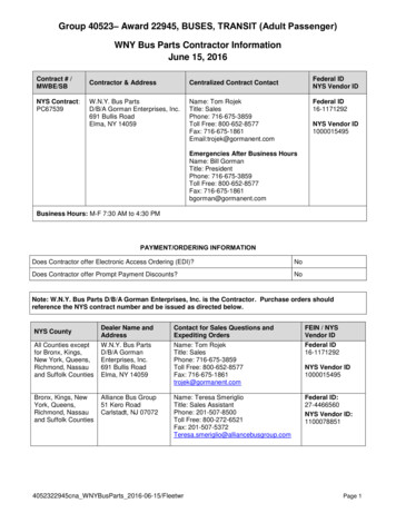
Transcription
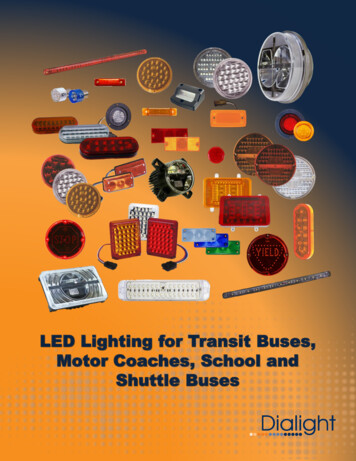
LED Lighting for Transit Buses,Motor Coaches, School andShuttle Buses
When safetycounts.More than 20 years of providingLED solutions for heavy dutybus applicationsSignal LightsMarker Lightswww.dialightsignalsandcomponents.comHead LightsAuxiliary Lights
The Leader in LED Bus LightsLED Signal Lights18 Series 4.8” x 1.95” 4 Mounting screws 1.19 “x 3.875”pattern 12 VDC and 24 VDC Auxiliary side turn lamp Amber48 Series 4” RoundGrommet or flange mountGrommet – 94001A12 VDC and 24 VDCFront turn signalAmber69 Series 2” x 6” OvalGrommet or flange mountGrommet - 96001A12 VDC and 24 VDCFront turn signalAmber80 Series 4.1” x 6.4”4 Mounting screws tabs12 VDC and 24 VDCS/T/T and rear turn signalsRed, Amber87 Series 1501 Route 34 SouthFarmingdale, NJ 07727Tel. 732-751-3119Fax. 732-751-577818.5” x 1”,2 screws on 17.25” centersAnodized metal base12 VDC and 24 VDCCenter High Mount Stop LampRed46 Series 4.0” RoundGrommet or Flange MountGrommet - 94001A12 VDC and 24 VDCS/T/T, reverse, and turn signalsRed, White, Amber68 Series 2” x 6” OvalGrommet or flange mountGrommet - 96001A12 VDC and 24 VDCS/T/T, reverse, and turn signalsRed, White, Amber70 / 71 Series 7” round4 screws on 6.3” diameter12 VDC and 24 VDCS/T/T, reverse, and rear turnRed, White, Amber84 Series 4.6” x 5.5”, Rear mounting bracket w/2 screwposts 12 VDC and 24 VDC Red, Amber, Whitewww.dialightsignalsandcomponents.com
LED Auxiliary Turn Signal Mounting Recommendations (when no guard is used) Mounting plane for the light must be flat and not roundedIf not provided with the light, select appropriate attachment screw such that the screw threads clear the through holes in thelightIf the light has a recessed area for the screw head, ensure the screw head has clearance between the side walls of the recessand the screw headFor lights with gaskets position the gasket behind the light to compensate for minor surface irregularities and to seal the lightto vehicle interface.Tighten screws to a torque of 12 to 14 in-lbs.Caution: Loctite is not recommended for use when installing the lights as Loctite contains chemical ingredients that are notcompatible with polycarbonate materialsCaution: Do not over-torque the screws when installing. Over- torqueing of the screws may add stress to the light that couldmake the light susceptible to failure from cleaning soaps that would attack the light at the stressed area resulting in potentialcracking of the light.LED Auxiliary Turn Signal Mounting Recommendations (when used with optional guard)Note: the use of an additional foam gasket and guard are optional but when the guard is used it must be used in conjunction withthe foam gasket supplies with the light Mounting plane for the light must be flat and not roundedIf not provided with the light, select appropriate attachment screw such that the screw threads clear the through holes in thelightIf the light has a recessed area for the screw head, ensure the screw head has clearance between the side walls of the recessand the screw headPosition light (1) and gasket (2)into the guard (3)Place gasket that additional gasket (4)between the back of the guard and the busMount the marker light with guard / gaskets to the bus positioning a nylon washer underneath the screw head so that thescrew head does not dig into the polycarbonate lens.Mounting torque should be limited to 12 -14 in-lbs.Caution: Loctite is not recommended for use when installing the lights as Loctite contains chemical ingredients that are notcompatible with polycarbonate materialsCaution: Do not over-torque the screws when installing. Over- torqueing of the screws may add stress to the light that couldmake the light susceptible to failure from cleaning soaps that would attack the light at the stressed area resulting in potentialcracking of the light.Item1234DescriptionAuxiliary Turn Signal LightFoam GasketLight GuardAdditional Foam Gasket123www.dialightsignalsandcomponents.com4
18 Series – Aux. Side TurnLED Vehicle LightingMechanical InformationMounting Hole Size 1.84” (46.7 mm)Mounting Torque12 – 14 in-lbs.Electrical SpecificationNominal Voltage12 VDC and 24 VDCTypical Current2 wire lights12 VDC – 120 mA @ 12 VDC24 VDC – 90 mA @ 24 VDC3 wire lights12 VDC – marker 50 mA,turn 210 mA @ 12 VDC24 VDC – marker 40 mAturn 175 mA @ 24 VDCApplication Auxiliary Side Turn (2 wire) Auxiliary Side Turn / Marker (3 wire)Features & BenefitsConstructionLens MaterialPolycarbonateHousing materialPolycarbonateSealing MethodVibration WeldedGasket MaterialClosed cell foamConnector*Maintenance savingDelphi 1201-0973 (2 wire) to position A – to position BLamp guards availableDelphi 1201-0717 (3 wire) Integral wiring Low profile Optional armor guards Reverse polarity protected Turn – pos. A, marker – pos. Bground – pos. CPhotometricMountingHorizontal* Consult Dialight for alternate connector optionswww.dialightsignalsandcomponents.com
AUX. TURNGROUNDMARKERConnections for 3 wire light0.185” max dia. 4 placesPart Number# 18011AB8282323Aux. side turnAux. marker / turnAux. side turnAux. marker / turn12 VDC12 VDC24 VDC24 VDCwww.dialightsignalsandcomponents.com
46 Series – 4” Round Signal LightsLED Vehicle LightingMechanical InformationMounting Hole Size 4.5”Mounting Torque12 – 14 in-lbs. (flange mount)Electrical SpecificationNominal Voltage12 VDC and 24 VDCTypical CurrentAmber turn12 VDC – 420 mA @ 12.8 VDC24 VDC – 250 mA @ 25 VDCWhite reverse12 VDC – 80 mA @ 14 VDC24 VDC – 65 mA @ 25 VDCApplication Rear Turn Reverse Stop / Tail / TurnRed S/T/T lights12 VDC – tail 35 mA @ 12.8 VDC,S/T 210 mA @ 12.8 VDC24 VDC – tail 30 mA @ 25 VDCS/T 130 mA @ 25 VDCCertifications & ratingsConstruction Lens MaterialHard coated polycarbonateSealing MethodConnector*PottedDelphi 1201-0973 turn / reverse to position A – to position BFMVSS 108Features & Benefits Integral wiring Potted designs Grommet or flange mount Reverse polarity protectedPhotometric Maintenance savingFMVSS 108Rear Turn, Reverse, S/T/T (see table)Mounting 5 SlopeDelphi 1201-0717 red S/T/TStop / Turn – pos. A, Tail – pos. Bground – pos. C* Consult Dialight for alternate connector optionswww.dialightsignalsandcomponents.com
Wire length is 12” nominal 5.50(3) .225 MOUNTING HOLES ON A 4.938 BOLT CIRCLE 120 APART(OMIT FOR GROMMET MOUNT)(3) .203 MOUNTINGHOLES ON A 4.938 BOLTCIRCLE 120 APART(POSITIVE)Connection for 2 wire turn and reverse lightsPart mberWhiteRedRear turnReverseS/T/TRear turnReverseS/T/TRear turnReverseS/T/TRear turnReverseS/T/T12 VDC12 VDC12 VDC24 VDC24 VDC24 VDC12 VDC12 VDC12 VDC24 VDC24 VDC24 VDC*White Flange also available contact ngGrommetBlack Flanged *
48 Series – 4” Front Turn SignalLED Vehicle LightingMechanical InformationMounting Hole Size 4.5”Mounting Torque12 – 14 in-lbs. (flange mount)Electrical SpecificationNominal Voltage12 VDC and 24 VDCTypical Current12 VDC – 420 mA @ 12.8 VDC24 VDC – 290 mA @ 25.6 VDCConstructionApplicationLens MaterialHard coated polycarbonate Sealing MethodConnector*PottedDelphi 1201-0973 (2 wire) to position A – to position BFront TurnCertifications & ratingsFMVSS 108PhotometricFeatures & BenefitsFMVSS 108Front Turn Integral wiringMounting 5 Slope Potted design Grommet or flange mount Reverse polarity protected Maintenance saving www.dialightsignalsandcomponents.com* Consult Dialight for alternate connector options
Wire length is 12” nominal(POSITIVE) 5.50(3) .225 MOUNTING HOLES ON A 4.938 BOLT CIRCLE 120 APART(OMIT FOR GROMMET MOUNT)(3) .203 MOUNTINGHOLES ON A 4.938 BOLTCIRCLE 120 APARTPart 63ABAmberAmberAmberAmberFront turnFront turnFront turnFront Turn12 VDC24 VDC12 VDC24 VDC*White Flange also available contact ngGrommetBlack Flanged*
68 Series – 2 x 6” Oval Signal LightsLED Vehicle LightingMechanical InformationMounting Hole Size See mounting hole pattern on page 2Mounting Torque12 – 14 in-lbs. (flange mount)Electrical SpecificationNominal Voltage12 VDC and 24 VDCTypical CurrentAmber turn12 VDC – 420 mA @ 12.8 VDC24 VDC – 260 mA @ 25.6 VDCWhite reverse12 VDC – 185 mA @ 12.8 VDC24 VDC – 85 mA @ 25.6 VDCApplication Rear Turn Reverse Stop / Tail / TurnRed S/T/T lights12 VDC – tail 20 mA @ 12.8 VDC,S/T 240 mA @ 12.8 VDC24 VDC – tail 9 mA @ 25.6 VDCS/T 95 mA @ 25.6 VDCCertifications & ratingsConstruction Lens MaterialHard coated polycarbonateSealing MethodConnector*PottedDelphi 1201-0973 turn / reverse to position A – to position BFMVSS 108Features & Benefits Integral wiring Potted designs Grommet or flange mount Reverse polarity protected Maintenance savingwww.dialightsignalsandcomponents.comDelphi 1201-0717 red S/T/TStop / Turn – pos. A, Tail – pos. Bground – pos. CPhotometricFMVSS 108Rear Turn, Reverse, S/T/T (see table)Mounting 5 Slope , Vertical or Horizontal* Consult Dialight for alternate connector options
1.2”1.3” w/FlangeWire length is 12” nominal2.875(4) .225 mounting holesfor flange mount only3.5(POSITIVE)Connection for 2 wire turn and reverse lightsPart mberWhiteRedRear turnReverseS/T/TRear turnReverseS/T/TRear turnReverseS/T/TRear turnReverseS/T/T12 VDC12 VDC12 VDC24 VDC24 VDC24 VDC12 VDC12 VDC12 VDC24 VDC24 VDC24 VDC*White Flange also available contact ngGrommetBlack Flanged *
69 Series – 2 x 6” Oval Front TurnLED Vehicle LightingMechanical InformationMounting Hole Size See mounting hole pattern on page 2Mounting Torque12 – 14 in-lbs. (flange mount)Electrical SpecificationNominal Voltage12 VDC and 24 VDCTypical CurrentAmber turn12 VDC – 420 mA @ 12.8 VDC24 VDC – 260 mA @ 25.6 VDCConstructionApplicationLens MaterialHard coated polycarbonate Sealing MethodConnector*PottedDelphi 1201-0973 (2 wire) to position A – to position BFront TurnCertifications & ratings FMVSS 108PhotometricFeatures & BenefitsFMVSS 108Front Turn, Integral wiringMounting 5 Slope , Vertical or Horizontal Potted designs* Consult Dialight for alternate connector options Grommet or flange mount Reverse polarity protected Maintenance savingwww.dialightsignalsandcomponents.com
1.2”1.3” w/FlangeWire length is 12” nominal(POSITIVE)2.875(4) .225 mounting holesfor flange mount onlyPart 63ABAmberAmberAmberAmberFront turnFront turnFront turnFront Turn12 VDC24 VDC12 VDC24 VDC*White Flange also available contact ntingGrommetBlack Flanged *
70 / 71 Series – 7” Round Signal LightsLED Vehicle LightingMechanical InformationMounting Hole Size See mounting hole pattern on page 2Mounting Torque12 – 14 in-lbs.Electrical SpecificationNominal Voltage12 VDC and 24 VDCTypical CurrentAmber turn12 VDC – 520 mA @ 12.8 VDC24 VDC – 280 mA @ 25 VDCWhite reverse12 VDC – 95 mA @ 12.8 VDC24 VDC – 90 mA @ 25 VDCApplication Rear Turn Reverse Stop / Tail / TurnRed S/T/T lights12 VDC – tail 55 mA @ 12.8 VDC,S/T 350 mA @ 12.8 VDC24 VDC – tail 45 mA @ 25 VDCS/T 200 mA @ 25 VDCCertifications & ratingsConstruction Lens MaterialHard coated polycarbonateSealing MethodConnector*PottedDelphi 1201-0973 turn / reverse to position A – to position BFMVSS 108Features & Benefits Integral wiring Potted designs Surface mounted Integral reflector on Red S/T/TPhotometric Reverse polarity protectedFMVSS 108Rear Turn, Reverse, S/T/T (see table) Maintenance savingMounting 5 SlopeDelphi 1201-0717 red S/T/TStop / Turn – pos. A, Tail – pos. Bground – pos. C* Consult Dialight for alternate connector optionswww.dialightsignalsandcomponents.com
(POSITIVE)Connection for 2 wire turn and reverse lightsPart 33RB71121CB71123CBAmberRedAmberRedWhiteWhiteRear turnS/T/TRear turnS/T/TReverseReverse12 VDC12 VDC24 VDC24 VDC12 VDC24 VDCwww.dialightsignalsandcomponents.com
80 Series – Signal LightsLED Vehicle LightingMechanical InformationMounting Hole Size See hole pattern on page 2Mounting Torque12 – 14 in-lbs.Electrical SpecificationNominal Voltage12 VDC and 24 VDCTypical CurrentAmber turn12 VDC – 330 mA @ 12.8 VDC24 VDC – 210 mA @ 24 VDCRed S/T/T lights12 VDC – tail 90 mA @ 12.8 VDC,S/T 460 mA @ 12.8 VDC24 VDC – tail 40 mA @ 24 VDCS/T 250 mA @ 24 VDCApplication Rear Turn Stop / Tail / TurnConstructionCertifications & ratingsLens MaterialHard coated polycarbonate Housing MaterialPolycarbonateSealing MethodConnector*Vibration weldedDelphi 1201-0973 turn / reverse to position A – to position BFMVSS 108Features & Benefits Integral wiring Reverse polarity protected Maintenance saving Retrofit for older MCI coaches and RTSPhotometricbusesFMVSS 108Rear Turn, S/T/T (see table)Mounting 5 SlopeDelphi 1201-0717 red S/T/TStop / Turn – pos. A, Tail – pos. Bground – pos. C* Consult Dialight for alternate connector optionswww.dialightsignalsandcomponents.com
(POSITIVE)Connection for 2 wire turn and reverse lightsPart 33RBAmberRedAmberRedRear turnS/T/TRear turnS/T/T12 VDC12 VDC24 VDC24 VDCwww.dialightsignalsandcomponents.com
84 Series – Signal LightsLED Vehicle LightingMechanical InformationMounting Hole Size See pattern on page 2Mounting Torque12 – 14 in-lbs.Electrical SpecificationNominal Voltage12 VDC and 24 VDCTypical CurrentAmber turn12 VDC – 400 mA @ 12.8 VDC24 VDC – 300 mA @ 25 VDCWhite reverse12 VDC – 170 mA @ 12.8 VDC24 VDC – 85 mA @ 25 VDCApplication Rear Turn Reverse Stop / Tail / TurnCertifications & ratings FMVSS 108Features & Benefits Integral wiring Potted designs Reverse polarity protected Maintenance savingwww.dialightsignalsandcomponents.comRed S/T/T lights12 VDC – tail 35 mA @ 12.8 VDC,S/T 330 mA @ 12.8 VDC24 VDC – tail 25 mA @ 25 VDCS/T 200 mA @ 25 VDCConstructionLens MaterialHard coated polycarbonateSealing MethodPottedMounting BracketConnector*Aluminum w/ 2 press fit studsDelphi 1201-0973 turn / reverse to position A – to position BDelphi 1201-0717 red S/T/TStop / Turn – pos. A, Tail – pos. Bground – pos. CPhotometricFMVSS 108Rear Turn, Reverse, S/T/T (see table)Mounting 5 Slope , Vertical or Horizontal* Consult Dialight for alternate connector options
Wire length is 12” nominal(POSITIVE)Connection for 2 wire turn and reverse lightswww.dialightsignalsandcomponents.com
87 Series – Center High Mount StopLED Vehicle LightingMechanical InformationMounting Hole Size See pattern on page 2Mounting Torque12 – 14 in-lbs.Electrical SpecificationNominal Voltage12 VDC and 24 VDCTypical Current12 VDC – 380 mA @ 12.8 VDC24 VDC – 240 mA @ 25.6 VDCConstructionLens MaterialHard coated polycarbonateApplicationBase MaterialAnodized aluminum Gasket MaterialClosed cell foamCertifications & ratingsSealing MethodPolyurethane seal to metal base Mounting BracketConnector*Aluminum w/ 2 press fit studsEDAC 568-001-000-100 (plug)to red wire positiveCenter High Mount Stop Lamp (CHMSL)FMVSS 108Features & Benefits Integral wiring Metal mounting base Reverse polarity protected Maintenance savingEDAC 568-001-000-200 (receptacle)to black wire groundPhotometricFMVSS 108Center high mount stop lampMounting 5 Slope , Vertical or Horizontal* Consult Dialight for alternate connector optionswww.dialightsignalsandcomponents.com
0.6 REF.8.32517.25Mounting Hole SpacingPart LCHMSL12 VDC24 VDCwww.dialightsignalsandcomponents.com
The Leader in LED Bus LightsLED Marker Lights13 Series 2.5” x 1.0”2.125” Screw mounting centers12 VDC and 24 VDCRed, Amber15 Series 4.0” x 0.88”3” Screw mounting centers12 VDC and 24 VDCRed, Amber16 Series 2” RoundGrommet mountGrommet – 91601A12 VDC and 24 VDCRed, Amber17 Series 2.5” Round2.5” Grommet or flange mountGrommet 91701A12 VDC and 24 VDCRed, Amber18 Series 4.8” x 1.95” 4 Mounting screws 1.19 “x3.875” pattern 12 VDC and 24 VDC Red, Amber20 Series 4.55” x 2.23”3.625” Screw mounting centers12 VDC and 24 VDCAmber45 Series 4.5” x 1.625”,4” Screw mounting centers12 VDC and 24 VDCRed, AmberConsult Dialight about connector options1501 Route 34 SouthFarmingdale, NJ 07727Tel. 732-751-3119Fax. 732-751-577845 Series (high angle version) 4.5” x 1.625”, 4” Screw mounting centers Vertical and Horizontalmounting from same unit Horizontal mount up to 55 rollback 12 VDC and 24 VDC Red, Amberwww.dialightsignalsandcomponents.com
LED Marker Light Mounting Recommendations (when no guard is used) Mounting plane for the light must be flat and not roundedIf not provided with the light, select appropriate attachment screw such that the screw threads clear the through holes inthe lightIf the light has a recessed area for the screw head, ensure the screw head has clearance between the side walls of therecess and the screw headFor lights with gaskets position the gasket behind the light to compensate for minor surface irregularities and to seal thelight to vehicle interface.Tighten screws to a torque of 12 to 14 in-lbs.Caution: Loctite is not recommended for use when installing the lights as Loctite contains chemical ingredients that arenot compatible with polycarbonate materialsCaution: Do not over-torque the screws when installing. Over- torqueing of the screws may add stress to the light thatcould make the light susceptible to failure from cleaning soaps that would attack the light at the stressed area resulting inpotential cracking of the light.LED Marker Light Mounting Recommendations (when used with optional guard)Note: the use of an additional foam gasket and guard are optional but when the guard is used it must be used in conjunctionwith the foam gasket supplies with the light Mounting plane for the light must be flat and not roundedIf not provided with the light, select appropriate attachment screw such that the screw threads clear the through holes inthe lightIf the light has a recessed area for the screw head, ensure the screw head has clearance between the side walls of therecess and the screw headPosition light (1) and gasket (2)into the guard (3)Place gasket that additional gasket (4)between the back of the guard and the busMount the marker light with guard / gaskets to the bus positioning a nylon washer underneath the screw head so thatthe screw head does not dig into the polycarbonate lens.Mounting torque should be limited to 12 -14 in-lbs.Caution: Loctite is not recommended for use when installing the lights as Loctite contains chemical ingredients that arenot compatible with polycarbonate materialsCaution: Do not over-torque the screws when installing. Over- torqueing of the screws may add stress to the light thatcould make the light susceptible to failure from cleaning soaps that would attack the light at the stressed area resulting inpotential cracking of the light.Item1234DescriptionMarker LightFoam GasketLight GuardAdditional Foam Gasket123www.dialightsignalsandcomponents.com4
13 Series – Marker LightLED Vehicle LightingMechanical InformationMounting Hole Size0.5 in (12.7 mm)Mounting Torque12 – 14 in-lbs.Electrical SpecificationNominal Voltage12 VDC and 24 VDCTypical Current12 VDC – 60 mA @ 13.5 VDC24 VDC – 45 mA @ 25.6 VDCApplicationConstruction LED Marker LightLens MaterialPolycarbonate LED Clearance LightSealingPotted designCertifications & RatingsGasket MaterialClosed cell foam Connector*.180 bullet terminalsWhite wire , Black wire –FMVSS 108Features & Benefits Integral wiringPhotometric Small footprintFMVSS 108Clearance / Marker Light Reverse polarity protectedMounting Limits Maintenance savingHorizontal mount 5 slope* Consult Dialight for alternate connector optionswww.dialightsignalsandcomponents.com
6.0”2.125”0.1752 placesPart rRedAmberRed12 VDC12 VDC24 VDC24 VDCwww.dialightsignalsandcomponents.com0.50”
15 Series – Marker LightLED Vehicle LightingMechanical InformationMounting Hole Size0.5 in (12.7 mm)two 0.22 holes, 3” on centersMounting Torque12 – 14 in-lbs.Electrical SpecificationNominal VoltageTypical CurrentApplication LED Marker Light LED Clearance Light12 VDC and 24 VDC12 VDCAmber 90 mA @ 13.5 VDCRed 60 mA @ 13.5 VDC24 VDCAmber 50 mA @24 VDCRed 50 mA @ 24 VDCConstructionCertifications & RatingsLens MaterialPolycarbonate SealingPotted designFeatures & BenefitsGasket MaterialClosed cell foam Integral wiringConnector* .180 bullet terminal (positive)#10 Ring terminal (negative)Surface mount Reverse polarity protectedPhotometric Maintenance saving FMVSS 108Mounting LimitsAluminum guard availableFMVSS 108Clearance / Marker LightHorizontal mountAmber 10 slopeRed 20 slope* Consult Dialight for alternate connector optionswww.dialightsignalsandcomponents.com
3.0”0.222 placesPart rRedAmberRed12 VDC12 VDC24 VDC24 VDCwww.dialightsignalsandcomponents.com0.50”
16 Series – 2” Marker LightLED Vehicle LightingMechanical InformationMounting Hole Size2 5/16” for use with grommetElectrical SpecificationNominal VoltageTypical Current24 VDCAmber 60 mA @ 25 VDCRed 40 mA @ 25 VDCApplication LED Marker Light LED Clearance LightCertifications & Ratings FMVSS 108Features & Benefits Integral wiring Grommet mount Reverse polarity protected Maintenance saving12 VDC and 24 VDC12 VDCAmber 55 mA @ 13.5 VDCRed 45 mA @ 13.5 VDCConstructionLens MaterialPolycarbonateHousing materialPolycarbonateSealing MethodVibration weldedConnector*Delphi 1201-0973 to position A – to position BPhotometricFMVSS 108Mounting LimitsClearance / Marker LightAmber 10 slopeRed 20 slope* Consult Dialight for alternate connector optionswww.dialightsignalsandcomponents.com
Suggested mounting hole – Grommet mount6.0” 1Part rRedAmberRed12 VDC12 VDC24 VDC24 VDCwww.dialightsignalsandcomponents.com
17 Series – 2.5” Marker LightLED Vehicle LightingMechanical InformationMounting Hole Size2 3/4” for use with grommet orflange mountElectrical SpecificationNominal VoltageTypical Current24 VDCAmber 60 mA @ 25 VDCRed 40 mA @ 25 VDCApplication LED Marker Light LED Clearance Light12 VDC and 24 VDC12 VDCAmber 55 mA @ 13.5 VDCRed 45 mA @ 13.5 VDCConstructionFeatures & BenefitsLens MaterialPolycarbonate Integral wiringHousing materialPolycarbonate Grommet mountSealing MethodVibration welded Flange Mount optionConnector*Delphi 1201-0973 to position A – to position B Closed cell foam gasket option forflange mount Reverse polarity protected Maintenance savingPhotometricFMVSS 108Mounting LimitsClearance / Marker LightAmber 10 slopeRed 20 slope* Consult Dialight for alternate connector optionswww.dialightsignalsandcomponents.com
2.536.0” 1Grommet mountSuggested mounting holeFlange mount5.5 1Part berRed12 VDC12 VDC24 VDC24 VDC12 VDC12 VDC24 VDC24 mmetBlack Flanged
18 Series – Marker LightLED Vehicle LightingMechanical InformationMounting Hole Size1.84” (46.7 mm)Mounting Torque12 – 14 in-lbs.Electrical SpecificationNominal Voltage12 VDC and 24 VDCTypical Current12 VDC – 110 mA @ 12 VDC24 VDC – 55 mA @ 24 VDCApplicationConstruction LED Marker LightLens MaterialPolycarbonate LED Clearance LightHousing materialPolycarbonateCertifications & RatingsSealing MethodVibration Welded Gasket MaterialClosed cell foamConnector*Delphi 1201-0973 to position A – to position BFMVSS 108Features & Benefits Integral wiring Low profilePhotometric Flexible mountingFMVSS 108Clearance / Marker Light Reverse polarity protectedMounting Limits Maintenance savingHorizontal or verticalup to 30 slope Lamp guards available* Consult Dialight for alternate connector optionswww.dialightsignalsandcomponents.com
0.185” max dia. 4 placesPart rRedAmberRed12 VDC12 VDC24 VDC24 VDCwww.dialightsignalsandcomponents.com
20 Series – Marker LightLED Vehicle LightingMechanical InformationMounting Hole SizeSee template on pg. 2Mounting Torque12 – 14 in-lbs.Electrical SpecificationNominal Voltage12 VDC and 24 VDCTypical Current12 VDC – 115 mA @ 13 VDC24 VDC – 35 mA @ 25 VDCApplicationConstruction LED Marker LightLens MaterialPolycarbonate LED Clearance LightHousing materialPolycarbonateCertifications & RatingsSealing MethodVibration Welded Gasket MaterialClosed cell foamConnector*Delphi 1201-0973 to position A – to position BFMVSS 108Features & Benefits Integral wiring Low profile recessed mount Reverse polarity protected Maintenance savingPhotometricFMVSS 108Mounting LimitsClearance / Marker LightHorizontal mount28 to 40 rollback* Consult Dialight for alternate connector optionswww.dialightsignalsandcomponents.com
1.4”2.5”3.625”Recommended mounting holesPart NumberColorVoltage20001AB20003ABAmberAmber12 VDC24 VDCwww.dialightsignalsandcomponents.com
45 Series – Marker LightLED Vehicle LightingMechanical InformationMounting Hole Size1.84” (46.7 mm)Mounting Torque12 – 14 in-lbs.Electrical SpecificationNominal Voltage12 VDC and 24 VDCTypical Current12 VDC – 55 mA @ 13.5 VDC24 VDC – 30 mA @ 27 VDCApplicationConstruction LED Marker LightLens MaterialHard coated polycarbonate LED Clearance LightHousing materialPolycarbonateCertifications & RatingsSealing MethodVibration Welded Gasket MaterialClosed cell foamConnector*Delphi 1201-0973 to position A – to position BFMVSS 108Features & Benefits Integral wiring Low profilePhotometric Integral reflectorFMVSS 108Clearance / Marker Light Reverse polarity protectedMounting Limits Maintenance savingHorizontal mountAmber 5 slopeRed 10 slope* Consult Dialight for alternate connector optionswww.dialightsignalsandcomponents.com
Part rRedAmberRed12 VDC12 VDC24 VDC24 VDCwww.dialightsignalsandcomponents.com
45 Series – High Angle Marker LightLED Vehicle LightingMechanical InformationMounting Hole Size0.68” (17.3 mm)Mounting Torque12 – 14 in-lbs.Electrical SpecificationNominal Voltage12 VDC and 24 VDCTypical Current12 VDC – 55 mA @ 12.8 VDC24 VDC – 50 mA @ 25.6 VDCApplicationConstruction LED Marker LightLens MaterialHard coated polycarbonate LED Clearance LightHousing materialPolycarbonateCertifications & RatingsSealing MethodVibration Welded Gasket MaterialClosed cell foamConnector*Delphi 1201-5791 (positive)Delphi 1201-0966 (negative)FMVSS 108Features & Benefits Integral wiring Low profile Integral reflector Horizontal or vertical mounting Reverse polarity protected Maintenance saving Convoluted loom covered wiresPhotometricFMVSS 108Mounting LimitsClearance / Marker LightHorizontal mountUp to 55 slope both colorsVertical MountAmber 5 slopeRed 10 slope* Consult Dialight for alternate connector optionswww.dialightsignalsandcomponents.com
Center mounting hole shown is the minimum size for the product. Thehole size may have to vary based on the connector option specified .Part rRedAmberRed12 VDC12 VDC24 VDC24 VDCwww.dialightsignalsandcomponents.com
The Leader in LED Bus LightsLED HeadlightsHLC 90 mm Low Beam FMVSS108 compliantStandard 90 mm formatIncludes alignment screws12 / 24 VDC operationHLB 90 mm High Beam FMVSS108 compliantStandard 90 mm formatIncludes alignment screws12 / 24 VDC operationHLC 4x6 Low Beam FMVSS108 compliant Standard 4” x 6” LB format 12 / 24 VDC operationHLB 4x6 High Beam FMVSS108 compliant Standard 4” x 6” HB format 12 / 24 VDC operationHLD 7” Dual Beam FMVSS108 compliantDual Beam (LB/HB)Standard 7” formatLens heater option available12 / 24 VDC operationConsult Dialight about connector options1501 Route 34 SouthFarmingdale, NJ 07727Tel. 732-751-3119Fax. 732-751-5778www.dialightsignalsandcomponents.com
LED Headlamp InstallationInstall each headlamp either into the appropriate mounting bucket or in the case of the 90 mm headlamps using thealignment screwInstall LED headlamp onto vehicle observing the “TOP” note on lens to correctly orient headlamp.Plug headlamp harness into harness from vehicle.Re-attach headlamp mounting panel to vehicle.Aim headlamps per the LED headlamp aiming instructions.Re-attach front trim panel to vehicle.Headlamp alignment:Before alignment is started,Check the tire inflation.Check that no other load is in the vehicle other than a half tank of fuel.Check that the headlamps are clean.Check for correct headlamp operation.Park the vehicle on a level surface approximately 7.6 meters (25 feet) from a vertical wall or screen directly in front of it.The center of the lamp is denoted by a dot on the lens. Aiming should be performed in a dark environment to effectivelysee the headlamp beam pattern.Measure the centers of the headlamps’ heights to the ground and record. Mark a horizontal reference line on the verticalwall or screen at the same height as the centers of the headlamps (marked C in Fig1). The beam pattern should beadjusted for both left and right headlamps as shown in Figure 1.Note that for VOR headlamps, the appearance of the beam pattern may vary between various manufacturers.www.dialightsignalsandcomponents.com
HLC / HLB 90 mm Low Beam / High BeamLED Vehicle Head LightsMechanical InformationMounting Hole Size See mounting hole pattern on page 2Electrical SpecificationNominal Voltage10 / 24 VDC Dual voltage operationTypical CurrentLow beam12 VDC – 1.2 A24 VDC – 0.58 AHigh beam12 VDC – 1.75 A24 VDC – 0.88 AUS Patent # 7,160,004 # 7,604,384 others pen
* Consult Dialight for alternate connector options 48 Series -4" Front Turn Signal LED Vehicle Lighting. www.dialightsignalsandcomponents.com (3) .203 MOUNTING HOLES ON A 4.938 BOLT CIRCLE 120 APART 5.50 (3) .225 MOUNTING HOLES ON A 4.938 BOLT CIRCLE 120 APART