Transcription
Optical Networks – BasicConcepts (Part 1)
Introduction What is an optical network?Optical devices and componentsBasic concepts in optical networkingOptimization of optical network designHow to handle faults in optical networks?Some recent research topics
What is an optical network? An optical network connects computers (or anyother device which can generate or store data inelectronic form) using optical fibers. Optical fibers are essentially very thin glasscylinders or filaments which carry signals in the formof light (optical signals).
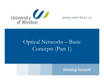
A transmitter connected to areceiver in an optical networkElectricalto OpticalSignalFiber (s)TransmitterOptical toElectricalsignalReceiverA lit-up bundle of fibers4
Global Optical Fiber Network5
Why do we need optical networks? Demand for bandwidth The tremendous growth of connected users online More and more bandwidth-intensive network applications: data browsing on the WWWApplications requiring large bandwidthvideo conferencingdownload movie
Advantages of optical networks High speed capability (theoretically possible to send 50Terabits per second using a single fiber) Low signal attenuation Low signal distortion Low power requirement Low material usage Small space requirements Low cost Immunity to electrical interference
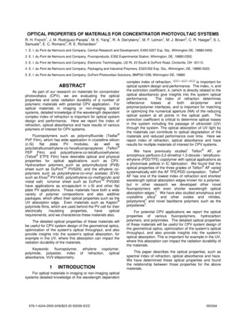
Optical Devices/components Optical Fiber consists of a cylindrical core of silica, with a refractive indexµ1, surrounded by cylindrical cladding, also of silica, with alower refractive index µ2.Figure 1: A fiber
An Optical FiberFigure 2: Structure of an Optical Fiber9
Propagation of a signal through a fiber How does an optical signal move through a fiber network send the optical signal at an angle greater than the critical anglesin-1 µ2 / µ1. Optical signals propagate through the core using a series of total internalreflections.Figure 3: Propagation using total internal reflectiobn
Optical fibers (Cont’d) data communication in an optical network use an optical carrier signal at some wavelength in the band of1450 to 1650 nm, at the source of the data, modulate the carrier with the data to becommunicated, send the modulated carrier towards the destination using a pathinvolving one or more fibers, when the signal reaches the destination, extract the data from theincoming signal using demodulation.
Wavelength Division Multiplexing The technology of using multiple optical signals on the samefiber is called wavelength division multiplexing (WDM). WDM Optical Network Divide the vast transmission bandwidth available on a fiber into severaldifferent smaller capacity “channels” – non-overlapping bandwidths, Each of these channels can be operated at a moderate bit rate (2.5-40Gb/s) that electronic circuits can handle, Each of these channels corresponds to a different carrier wavelength.
Transmission spectrum of fibersUsable BandwidthsFigure 4: Transmission spectrum of optical fibers.
Channel spacing or guard band in WDM– In WDM networks, eachsignal on a fiber is given afixed bandwidth.– In order to avoid interferencebetween signals, a fixedspacing is maintainedbetween signals usingadjacent bandwidths, calledas “guard band”.– Signal Bandwidth 10 GHz– Channel Spacing 100 GHzFigure 5: channels on a fiber14
Data Transmission in WDM networks Carrier Frequency: Digital Data Modulated signal15Figure 6: Modulated optical signalhttp://epq.com.co/softw internet/nag1/c4049.htm
What do we need to achieve WDMCommunicationTransmitter – convert data to a modulated optical signalReceiver – Convert a modulated optical signal to dataMultiplexer – to combine multiple optical signalsDemultiplexer – to separate signals having different carrier wavelengthsRouters – to direct the signals from the source to the destinationAdd- drop multiplexers – to add new signals to a fiber and extract some signalsDeMultiplexerMultiplexerOptical gure 7: Wavelength Division Multiplexing (WDM)16
Optical Devices/components Multiplexer (MUX) has a number of inputs, each carrying signals using a distinct channel. generates an output that combines all the signals.Figure 8: A 4-input Multiplexer
Optical Devices/components Demultiplexer (DEMUX) serves the opposite purpose -- its input is a fiber carrying n opticalsignals, with the i th signal using channel ci. has at least m outputs, with the ith output carrying the optical signal usingchannel ci, for all i; 1 i n.Figure 9: A 4-output Demultiplexer
Optical Devices/components Optical add-drop multiplexer(OADM) ADM: A pair consisting of a MUXand a DEMUX, where some of theoutputs from the DEMUX are notconnected to any of the inputs of theMUX. Each output of the DEMUX, notconnected to an input of theMUX, is connected to a receiver. Each input to the MUX which isnot connected to an output ofthe DEMUX is connected to theoutput of atransmitter/modulator. Add-drop multiplexers using opticaldevices are called Optical Add/dropMultiplexers (OADM).Figure 10: An optical add-dropmultiplexer (OADM)
Optical Devices/components End nodes: sources or destinations of data (typicallycomputers). Optical routers: direct each incoming optical signal to anappropriate outgoing fiber.
Optical Devices/componentsFigure 12: Use of add drop multiplexersand demultiplexers End node Ex (Ey) has transmitters(receivers) ti, tj (ri, rj) tuned towavelengths λi, , λj. The data in electronic form is the inputto transmitter ti , and is converted tooptical signals using wavelength λi. The optical signal using λi is routedthrough a number of intermediate endnodes Ep,Eq, ,Er to the destination Ey.
Optical Devices/components Tasks of End-Node receive optical signals from thepreceding node, separate the different optical signals onthe input fiber, Convert incoming signals, intended foritself to electronic form, forward, without electronic processing,other incoming signals intended forother end-nodes, convert, to optical signal(s), electronicdata that have to be communicated toother end-node(s), combine the optical signals send theseoptical signals using the outgoing fiberfrom itself.Figure 12: Use of add drop multiplexersand demultiplexers
Point to point communication in an OpticalNetworkFigure 11: Point to point communication in an optical network
Types of WDM networks Categorizations of WDM Networks Broadcast-and-select Networks Wavelength-Routed Networks
Broadcast-and-select Networks Typically a local network with a small number (NE) of end-nodes,Each end-node equipped with one or more transmitters and receivers.All the end-nodes are connected to a passive star coupler.Capable of supporting both unicast and multicast communicationMay be either a single-hop or a multi-hop network.Figure 15: A broadcast-and-select network
Broadcast-and-select Networks Unicast communication: the source end node selects an appropriate wavelength λp and broadcaststhe data to all end nodes using the wavelength λp. Receiver at destination tuned to λp ; receivers at all other end nodes aretuned to wavelengths different from λp. Data is detected and processed only at the destination node. A broadcast-and-select network is simple and easy to implementbut the size of the network is limited due to the requirement thatthe signal has to be broadcast to all end nodes.
Wavelength-Routed Networks the wavelength of the optical signal and the fiber it isusing determine the subsequent path used by the signal. Since each optical signal is sent along a specified pathand not broadcast to all nodes in the network, thepower requirement of such a network is lower than thatof a broadcast-and-select network.
Physical Topology of a wavelength routed network A circle represents an end node. A rectangle represents a routernode. directed line represents a fiber. A These fibers are unidirectionaland the arrow on the line givesthe direction in which opticalsignals can flow.Figure 16: The physical topology of atypical WDM network
Lightpath an optical connectionfrom one end node toanother. starts from an end node,traverses a number offibers and router nodes,and ends in another endnode. used to carry data in theform of encoded opticalsignals.λ12λ1λ113λ2λ24LightpathFigure 17: Lightpaths in an optical network
Logical Topology (Virtual Topology) view the lightpaths as edges of a directed graph GL where thenodes of GL are the end nodes of the physical topology. the edges of such a graph GL are called logical edges. A directed path through a logical topology is called a logical path.
Lightpath and Logical TopologyE1L5E1R1L1L5E4L3L3R4R2L2Lightpath L1R3L2E2E3Lightpath L2L1E3L4E2FiberL4E4Lightpath L3Lightpath L4Lightpath L5Figure 18: Some lightpaths on the physicaltopology shown in figure 10.Figure 19: The logical topology GLcorresponding to the lightpathsshown in Figure 18.
Wavelength Routed Networks In summary, wavelengthrouted WDM networks Route signals selectively basedon wavelength Routing is done in the opticaldomain Lightpath – a basiccommunication mechanism1423Optical routerEnd nodeλ1λ2Figure 20: lightpaths on a network
Wavelength Clash Constraint No two lightpaths mayuse the samewavelength, if they shareany fiber link.6304152L1(λ1) : 0 3 4 5 7L2(λ2) : 2 4 5 6Figure 21: wavelength clashmust be avoided337
Wavelength Continuity Constraint A lightpath from a source Ex to a destination Ey, on all fibers inits path Ex Ri Rj Rk Ey, uses the same channelci. no other signal on the fibers Ex Ri , Ri Rj , , Rk Ey isallowed to use the channel ci. (See previous slide) The carrier wavelength of a lightpath does not change fromfiber to fiber. When considering a route for a lightpath, some channel ci , 1 i nch must be available on every fiber on the route. See previous slides for an example
Design objectives of wavelength routed WDMnetworks Minimize the capital and operational costs. Maximize the network– throughput.– scalability.– survivability.– quality of service (QoS)
RWA in Wavelength Routed Networks Routing and wavelength assignment (RWA) Each lightpath must be assigned a route over the physicalnetwork, and a specific channel on each fiber it traverses.11λ12λ2244λ2λ133end-nodeEnd nodelightpathFigure 22Optical routerλ1λ2
Static Lightpath Allocation in Wavelength Routed Networks Set up lightpaths on a semi-permanent basis. The lightpaths will continue to exist for a relatively longperiod of time (weeks or months) once set-up. When the communication pattern changes sufficiently, theexisting lightpaths will be taken down and new lightpathswill be set up to handle the changes in traffic.
Connection Requests (static allocation)Static Requests:Source Destination1 6123 61 43541 5Notes: For 1 6 there are many routes ( e.g., 1 3 4 6, 1 2 4 6) On each fiber we have many channels Wavelength continuity constraint and wavelength clashconstraint must be satisfied Problem known to be NP-complete6Figure 23:Physical topologyof an opticalnetwork38
Dynamic Lightpath Allocation Lightpaths are set up on demand. When a communication is over, the corresponding lightpathis taken down.
Connection Requests (Dynamic Requests)Existing LightpathsSource DestinationStartTimeDurationEventType1 61030Setup3 62575Setup1 640-Tear down1 46025Setup3 6100-Tear down132546Random arrival time and random durationTear down time Start time Duration40Figure 24:Dynamic RWA
WDM Network design Traffic matrix T [t(i,j)] represents the trafficrequirements. The entry t(i,j) in row i and column j oftraffic matrix T denotes the amount of traffic from endnode Ei to Ej, i j.
A Traffic Matrix– Specify the data communication requests between a node-pair.– Often expressed in OC-n notation. OC-n n X 51.8 MbpsNodesSource1Destination23 j n1OC-3 OC-6 OC-12 OC-242:itij.:nT (tsd)42
WDM Network design Some popular units for specifying datacommunication: megabits/second (Mbps), gigabits/second (Gbps), the signal rate, using the Optical Carrier level notation(OC-n), where the base rate (OC-1) is 51.84 Mbps andOC-n means n x 51.84 Mbps. As a fraction of lightpath capacity
Types of scenarios Single-hop vs. Multi-hop networks In a single-hop network, all communicationuses a path length of one logical edge. Direct lightpath from source to destination also called all-optical networks, communication always in opticaldomain. No opto-electronic conversion in theintermediate node Example: 0 1, 1 2, 2 0, 2 3.Figure 25: The logicaltopology of an alloptical network
Multi-hop networks In a multi-hop network, some datacommunication involves morethan one lightpath. Uses a sequence of lightpaths Hop through intermediate nodes Opto-electronic conversionsneeded Example: 0 1 2, 1 2 0needs multi-hopFigure 26: Communication from 0 to2 (or 1 to 0) requires multi-hop
Multihop WDM Network design The constraints in designing a multi-hop wavelength-routednetwork using static lightpath allocation: The physical topology of the network. The optical hardware available at each end node whichdetermines how many lightpaths may originate from or end atthat end node. The characteristics of the fibers, which, for example, determinehow many lightpaths may be allowed in a single fiber. the amount of data that may be carried by a single lightpath, The traffic requirements between each pair of end nodes.
Optimal solution for static RWAStatic RWA Given: A physical fibre topology Number of wavelengths (channels)available on each fibre. A set of lightpaths to be established overthe physical topology. A lightpath isspecified by the source and destinationnode corresponding to the start and endof the lightpath.1 32 14 23 14 32134λ12 Goal: Find a route over the physical topology,for each lightpath. Find a single wavelength to be used foreach lightpath on all its hops. Minimize the total number of hops,considering all lightpaths.1λ1λ13λ2λ24Figure 27: static RWA illustrated
ILP for Multi-hop network designInteger Variables 1, if and only if the lth lightpathuses physical link e(i j). wk,l 1, if and only if the lth lightpathis assigned channel k.Continuous Variables 1, if and only if the lthlightpath is assigned channel kon physical link e.λ12λ1λ113λ2λ24Figure 281 32 14 23 14 3
ILP for Multi-hop network designMin l i j ExijSubject to:l lx ji xijl j i j Ej j i E1, if i s 1, if i d0, otherwise{ i N , l Lλ1λ11K max wk ,l 1λ12 l3λ2k 1xijl wk ,l δ ijk ,l 1, i j E , l L, k Klijx δk ,lij, i j E , l L, k Kwk ,l δ ijk ,l , i j E , l L, k Kλ241 32 14 23 14 3
What is an optical network? An ptica etwr connects computers (or any other device which can generate or store data in electronic form) using optical fibers.