Transcription
INTRODUCTION TOTRANSMISSION LINESPART IIDR. FARID FARAHMANDFALL 2012
Transmission Line Model
Perfect Conductor and Perfect Dielectric (notes)
Simulation Example
Transmission Line Model
Transmission-Line EquationsRemember:Kirchhoff Voltage Law:Vin-Vout – VRʼ – VLʼ 0Kirchhoff Current Law:Ae jθ A cos(θ ) Aj sin(θ )cos(θ ) A Re[ Ae jθ ]Note:sin(θ ) A Im[ Ae jθ ]E ( z ) E ( z ) e jθ zVL L . di/dtIc C . dv/dt e jθ 1C A jB θ tanIin – Iout – Icʼ – IGʼ 0B; C A2 B 2A
Transmission-Line Equationsac signals: use phasorsTransmissionLine Equationin PhasorForm
Derivation of Wave EquationsTransmission Line EquationFirst Order Coupled Equations!WE WANT UNCOUPLED FORM!complex propagationconstantattenuation constant(Neper/m)Phase constantCombining the two equations leads to:Second-order differential equationWave Equations for Transmission LineImpedance and Shunt Admittance of the linePay Attention to UNITS!
Solution of Wave Equations (cont.)Characteristic Impedance of the Line (ohm)Note that Zo isNOT V(z)/I(z)Using:Proposed form of solution:It followsthat:So What does V and V- Represent?Pay att. ToDirection
Solution of Wave Equations (cont.)So, V(z) and I(z) have two parts:Applet for standing wave:http://www.physics.smu.edu/ olness/www/05fall1320/applet/pipe-waves.html
Example: Air-LineAssume the following waves:V ( z, t ) 10 cos(2π 700 106 20 z 5)PerfectConductorà Rs 0à R’ 0Perfect Dielecà COND 0 à G’ 0I ( z, t ) 0.2 cos(2π 700 106 20 z 5)Assume having perfect dielectricinsulator and the wire haveperfect conductivity with no lossDraw the transmission line model andFind Cʼ and Lʼ; Assume perfect conductorand perfect dielectric materials are used!Note: If atten. Is zero à real part MUST be zero!
Transmission Line Characteristics Line characterization PropagationConstant (function of frequency) Impedance (function of frequency)n Lossy or LoslessIf lossless (low ohmic losses) Veryhigh conductivity for the insulator Negligible conductivity for the dielectric
Lossless Transmission LineIfThen:What is Zo?Non-dispersive line:All frequency components have the same speed!
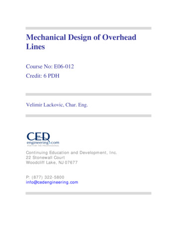
The Big Idea .Impedance is measured at difference points in the circuit!ZLV oZoZinWhat is the voltage/current magnitude at different points on theline in the presence of load?
Voltage Reflection CoefficientConsider looking from the Load point of viewAt the load (z 0):ReflectioncoefficientThe smallerthe better!Normalized loadimpedance
Expressing wave in phasor form: Remember: If lossless no attenuation constantAll of these wave representationsare along theTransmission Line
Special Line Conditions (Lossless) Matching line ZL Zo à Γ 0; Open Circuit ZL INF Vref 0à Γ 1; Vref VincShort Circuit ZL 0à Γ -1; Vref -VincVref Vreflected ; Vinc VincidentRemember:Everything is with respectto the load so far!
Voltage Reflection CoefficientPayattention!Normalized loadimpedance
ExampleExampleExampleNotes
Standing WavesFinding Voltage MagnitudeWe are interested to know whathappens to the magnitude of the V as such interference is created!When lossless!Remember: Standing wave is createddue to interference between thetraveling waves (incident & reflected)Note: When there is no REFLECTION Coef. Of Ref. 0 à No standing wave!
Standing ue to standing wave the received wave at the load is now different
Standing WavesFinding Voltage Magnitudevoltage magnitude at z -dcurrent magnitude at the sourceRemember max current occurswhere minimum voltage occurs(indicating the two waves areinterfering destructively)!Letʼs see how the magnitude looks like at different zvalues!
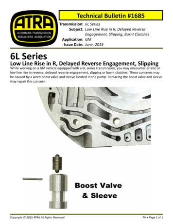
Standing Wave Patterns for 3 Types of Loads(Matched, Open, Short)No reflection, No standing wave Matching line Short Circuit ZL Zo à Γ 0; Vref 0ZL 0 à Γ -1; Vref -Vinc (angle –/ π)Open Circuit ZL INF à Γ 1; Vref Vinc (angle is 0)Remember max current occurswhere minimum voltage occurs!
Standing Wave Patterns for 3 Types of Loads(Matched, Open, Short)No reflection, No standing waveBUTMatchingWHENDOlineMAX& MINShort CircuitVoltages Occur? ZL Zo à Γ 0; Vref 0 ZL 0 à Γ -1; Vref -Vinc (angle –/ π) Open Circuit ZL INF à Γ 1; Vref Vinc (angle is 0)Remember max current occurswhere minimum voltage occurs!
Finding Maxima & MinimaOf Voltage MagnitudeS Voltage Standing Wave Ratio(VSWR)For a matched load: S 1For a short, open, or purely reactive load:S(open) S(short) INF where Γ 1;
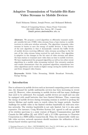
Example Measuring ZL with a Slotted LineSlotted Coaxial Line
What is the Reflection Coefficient (Γd) at any pointaway from the load? (assume lossless line)At a distance d from the load:Wave impedance
Frameset.htm
tmlExampleNotes
Input ImpedanceWave ImpedanceZdAt input, d l:
Short-Circuit/Open-Circuit Method For a line of known length l, measurements of itsinput impedance, one when terminated in a shortand another when terminated in an open, can beused to find its characteristic impedance Z0 andelectrical length
Standing Wave Properties
Power Flow How much power is flowing and reflected? InstantaneousP(d,t) v(d,t).i(d,t)n Incidentn Reflected Averagepower: Pav Pavi Pavrn Time-domainApproachn Phasor-domain Approach (z and t independent)n ½ Re{I*(z) . V(z)}
Average Power(Phasor Approach)Avg Power: ½ Re{I(z) * V (z)}Fraction of power reflected!
Summary
Practice1- Assume the load is 100 j50 connected to a 50 ohm line. Find coefficient of reflection (mag, &angle) and SWR. Is it matched well?2- For a 50 ohm lossless transmission line terminated in a load impedance ZL 100 j50 ohm,determine the fraction of the average incident power reflected by the load. Also, what is themagnitude of the average reflected power if Vo 1?3- Make sure you understand the slotted line problem.4- Complete the Simulation Lab answer the following questions:- Remove the MLOC so the TEE will be open. How does the result change? Take asnapshot. Briefly explain.- In the original circuit, what happen if we use paper as the dielectric (paper has er of3.85). Take a snapshot. Briefly explain.- For the obtained Zo in your Smith Chart calculate the admittance. You must show all your work.- What exactly is mag(S11)? How is it different from coefficient of reflection? Is thereflection of coefficient measured at the source or load?- What happens if the impedance of the source (TERM1) is changed to 25 ohm? Howdoes the impedance on the smith chart change?- How do you calculate the effective length?
Everything is with respect to the load so far! Vref Vreflected ; Vinc Vincident. Voltage Reflection Coefficient Normalized load impedance Pay attention! Example Example Example Notes . Standing Waves Finding Voltage Magnitude Note: When there is no REFLECTION Coef. Of Ref.