Transcription
White PaperThe Cisco Edge Analytics Fabric SystemA new approach for enabling hyperdistributed implementationsContentsExecutive Summary . 2Introduction . 2IoT System Basics . 3IoT System Flexibility and Scalability . 4Dealing with Complexity. 5IoT System Structure . 5Microservices . 7Microservice Implementation . 8The Message Router . 10Edge/Fog Database . 15Intermediate Processing Between Microservices . 16Tight Coupling. 18Development and Management Tools . 16Data Leverage . 20Control . 21 2016 Cisco and/or its affiliates. All rights reserved. This document is Cisco Public.Page 1 of 22
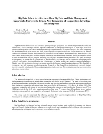
Executive SummaryThis white paper describes a software system that provides the framework for the Internet of Things (IoT). Itdramatically simplifies the task of creating sophisticated IoT systems.This system’s key capabilities include: A framework for edge and fog processing. High performance. Reusable microservices for collecting data from, and providing control over, devices and machines,as well as processing the data prior to delivery to its destination. Different options for reliable transport of data through the system, encompassing both batchand real-time streaming options. Flexible mechanisms for integration with IT systems, reporting, and analytics. An architectural framework to extend fog processing to multiple tiers: east west (fog to fog) andnorth south (hierarchical processing leveraging network topology). Easy-to-use GUI tools to simplify development, deployment, and operation for all aspects of the system. A pervasive control paradigm and flow of information back to microservices, devices and machinesfor management, control, optimization and specific actions. A completely open and polyglot system, where third parties can provide devices, processingstorage, software modules, analytics, applications, or any combination thereof.This is the technology that makes IoT approachable, and leads to much faster industry adoptionof the vision of IoT.IntroductionIoT is a combination of data generating devices, communications, and data processing that effectively leveragesmachine generated information for business advantage, including analytics and integration with existing ITsystems.Figure 1 is a conceptual model that depicts the different parts of an IoT system in a layered approach. Thisillustrative model has been adopted by the IoT World Forum as its reference model 1, with the goal of taking the firststep in converting from a concept to a tutorial diagram.1Building and Internet of Things: An IoT Reference Model, net-of-things-an-iotreference-model 2016 Cisco and/or its affiliates. All rights reserved. This document is Cisco Public.Page 2 of 22
Figure 1.IoT World Forum Reference ModelIoT is something that the industry has never seen before. It has been described in numerous ways, such as: The next generation of the Internet. An evolution of the networking industry enabling everything to become interconnected, with IoT focused onmachine communications. The bridging of operational technology (OT) and information technology (IT). The capture of information from machines that enable analytics that were never before possible. Pervasive control of highly distributed actuators.Despite the different perspectives on this industry movement, one thing is very clear: IoT requires infrastructuresoftware unlike that which currently exists. The handling of machine-generated data, combined with the scope ofvery large-scale systems (in terms of geography, number of data generating devices, diversity of manufacturers,frequency of data generation, and overall data volume) including machines, IT, and analytics, is new to theindustry. A new form of IoT enablement middleware is required.IoT System BasicsTo meet this need, Cisco has created a new type of software system that complements its advanced networkingand computing hardware. This system is driven by a complex set of requirements: Flexible: It handles a wide variety of IoT needs. Repeatable: Once configured to handle a manufacturing cell, an oil well, a parking lot lighting system,or other systems, it can be easily replicated. 2016 Cisco and/or its affiliates. All rights reserved. This document is Cisco Public.Page 3 of 22
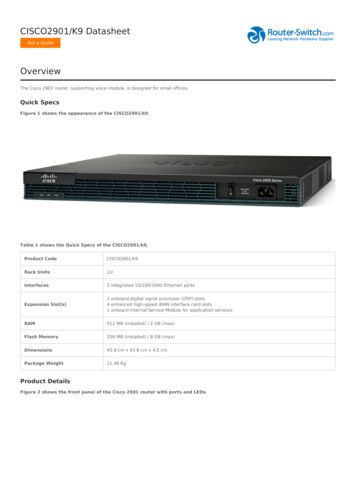
Scalable: Some IoT systems generate more data than Big Data. Many terabytes of data can be generatedquickly. The ability to effectively handle this load requires sophisticated engineering. Robust: Many industrial IoT systems must be monitored, managed, secure, and highly available. Using awell-tested system, a validated design, and a proven methodology yields better results. Control and action: Most industrial IoT solutions today are focused on data collection and actuation.As previously mentioned, the system described in this document accomplishes those tasks in a unique,flexible, and repeatable manner. Further, control and automation can be implemented with a pre-definedpolicy architecture. Multi-purpose: For example, the value and use of data changes over time. Initially collected data is valuablefor monitoring and control where latency and responsiveness may be crucial, later analytics can createoptimization and production improvements or cost savings, and in the long term IoT data may be requiredfor compliance assurance.The system described in this document is the infrastructure for Cisco IoT solutions, is used by Cisco AdvancedServices for custom implementations, and is available to Cisco partners and third parties as a stand-alone offeringto enable them to convert their IoT concepts into reality in record time.IoT System Flexibility and ScalabilityBecause customers have a wide variety of IoT use cases, the system is designed to handle complexity, as well assatisfying the needs of simpler problems. One complex example might be the need to bring data from thousands ofoff shore oil wells and reliably transport it half way around the world to a data center where it is integrated withmultiple applications. Another, simpler example might be a supervisory control system completely contained in amanufacturing cell, with only one user.Figure 2.Oil and Gas Example for Data Processing on Platforms, at the Regional Data Center, and the Main Data Center 2016 Cisco and/or its affiliates. All rights reserved. This document is Cisco Public.Page 4 of 22
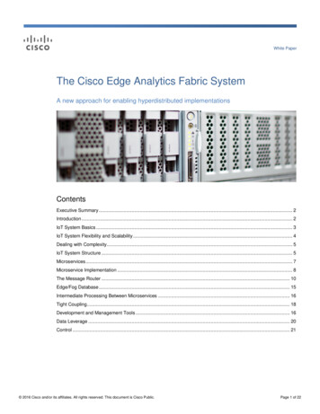
To accommodate the wide range of system scope, topologies, and geography, the system is modular. It can beused in scenarios where computing is executed in two, three, or four places. Processing is completed where mostappropriate, and data filtering, aggregation, and compression is performed at the edge, in the fog, or at the centerto optimize performance and scalability, and minimize networking costs.The diagram in Figure 3 depicts some of the basic options.Figure 3.Data Computing Tiers: Optional Fog Nodes for Better PerformanceDealing with ComplexityImplementing a solution quickly, with a solid scalable architecture and in a minimum amount of time, is a significantaccomplishment. To accelerate the widespread adoption of IoT systems, the time required to create complexsystems must be reduced from years to weeks. The system contains not only a sophisticated infrastructure thatmeets the requirements previously listed, but also a set of GUI tools that replace coding, dramatically decreasesskill requirements, dramatically shortens the time to operation, and dramatically increases the quality of theresulting system. These tools achieve several objectives: Ease of development and operation provided by these tools is a major improvement over pure open sourceproducts. Flexibility to adjust a solution quickly to changing needs is critical. Incremental complexity of a growing system that changes over time and is contained through the use oftools that support incremental changes and allow monitoring of the entire system.Example development tools are depicted in Figures 7 through 11.IoT System StructureDifferent scenarios require different approaches. The system is built with different hardware and software modules.With modularity in mind, the system is divided into different functional subsystems (Figure 4): 2016 Cisco and/or its affiliates. All rights reserved. This document is Cisco Public.Page 5 of 22
Data Acquisition: Interacting with devices (many times through a non-IP protocol), receiving data from thedevice, and handling the initial processing of the data. Data Retention: Data can be stored, transformed, and retrieved on demand from all locations within thesystem. Data Transport: Reliable delivery and transformation of data, assuring that the data is delivered to thedestination application and/or data repository guaranteed, exactly once, in order. Data Processing: Trade-offs are made regarding the location of the processing of telemetry data obtainedfrom devices. In some cases, edge processing is required. In other cases, aggregation of data from a widevariety of sources is necessary. And in other cases, the data cannot be fully leveraged until it reaches adata center or a cloud. All options are available with this system. Data Leverage: Enabling the consumer of the data to leverage it quickly and effectively. Examples include:reporting or business intelligence; creating an environment for analytics; responding appropriately to anevent; or providing data to existing IT systems. Each of these four categories requires different datamanipulation. A single system may encompass more than one of these categories, and they may occur indifferent tiers. Control: The system must be secure, extensible over time, changeable while running, and it must bemonitored as it operates. All of these aspects are implemented or enabled by the system.The modularity of the system provides independence and decoupling between the different subsystems, and addsgreat value to the customer through the lifetime of the system by allowing for growth using new modules fromCisco or third parties, or combining Cisco software with other third-party software as needed. This is anopen system supporting both proprietary and standard interfaces, with metadata management throughout thesystem.This modularity distributes the processing and logic throughout the system. It can occur at one or more edgenodes, in a fog node, by data center applications, or in a cloud. The software in this hyperdistributed system ispackaged as microservices. The system provides a uniform architecture to assure interoperability betweenmicroservices, common data encoding across all microservices, and different modes of communicating betweenthem. More details about what defines a microservice, the messaging system between microservices, and the toolsfor creating microservices are provided in following sections. 2016 Cisco and/or its affiliates. All rights reserved. This document is Cisco Public.Page 6 of 22
Figure 4.Cisco IoT System CapabilitiesFor each of these functions there are a rich variety of options and processing modules that can be invoked tocustomize the system to the customers’ exact needs (Figure 5). These options are provided by independentsoftware modules that connect to each other using a common architecture, providing the flexibility to add, modify,and upgrade as required over time. This openness allows for many ecosystem partners and developers to addfunctionality and enhance the system.Figure 5.IoT System Example: Functional System ProcessingMicroservicesProcessing is distributed throughout the system. For example, data from a device could be inspected, filtered,analyzed, and transformed in an edge node. Eventually, that data (or a derivative of it) can be used for analytics in 2016 Cisco and/or its affiliates. All rights reserved. This document is Cisco Public.Page 7 of 22
the cloud. We therefore need a uniform way to package software modules that perform one or more functions, butmay or may not qualify to be called a complete application. These modules are called microservices.Some key motivations for running microservices at the edge include: Reduce the data at the edge: Filter and reduce data before being sent to a cloud or on-premises datacenter. Sometimes this is required due to massive volumes of data and limited network bandwidth. Analyze the data at the edge: If the consumer of the data is local to the data generating device, such as ina factory control-loop feedback system, analysis of the data is best done local to where it is generated. Time series capture: If time precision is required as to when the measurement or sensing occurred, thedata is typically captured, time-stamped, and stored as close to the edge as possible, usually in a historiandatabase.Some microservices run at the edge, such as in an edge router or an IoT gateway. Some run in afog node, perhaps to aggregate data generated by many edge processing nodes. And some run in a data center orcloud. Regardless of location, all microservices in the system need to have certain attributes incommon, including: Interaction with each other through a common communication system. This system is called a messagerouter system and is described in detail in the Message Router section of this paper. Adherence to common data structures and encoding, so as data is passed between them, the value of thedata points remains unchanged. Share certain capabilities. For example, if one microservice publishes data on a certain topic, all subscribersto that topic will receive copies. Compliance with a common security system. Able to be monitored in the same way so that the entire system can be monitored. Common deployment model, so the complexity of the system grows at a much slower rate than the size ofthe system. Common infrastructure to interact in the same way to system GUI tools that are provided by Cisco as part ofthe system.The framework for building and deploying compatible microservices is a major aspect of Cisco’s IoT system.Microservice ImplementationCisco’s microservices framework is designed to be extremely flexible: There is no size or structural requirements for a microservice other than its interface to the messagerouter system. A microservice could be a few lines of code, an interface to a database, a user interface, oran application of any size. Microservices are not limited to specific functionality. A service could be a Modbus communicationservice, a data transformation service, a data analytic service, a bridge to move data in or out of a datastorage system, or a complete application. Services can be developed in a variety of languages, such as C, C#, Java, JavaScript, Ruby, Python,and Dart. 2016 Cisco and/or its affiliates. All rights reserved. This document is Cisco Public.Page 8 of 22
Services can be developed using familiar software development design patterns. All services can interact with each other and pass messages between them. Communication between services is typically loosely coupled (asynchronous), enablingunlimited scalability.The following sections describe the key design aspects of service development.Service DescriptionA service description captures the details of service capabilities in a declarative fashion. This includes theRPC/Pub-Sub endpoints, associated message schemas & models. The idea behind this is multi-fold. One, wewould like to have certain common service infrastructure (registration, invocation etc.) aspects, while hiding theservice implementations from the framework implementation choices (router implementation, for example).Second, this helps service developers focus on one interface to expose their capabilities. The framework and toolscan use this service description to generate various interfaces.Service DependencyServices can indicate other services they depend on. There are two kinds of dependencies taken into account. Onekind is a hard dependency. In this case, a service cannot function unless the dependent services are in place.Typically, this kind of dependency is limited to core services that the framework provides. The second kind is a softdependency. This means that service startup is not affected by the dependency. Service A can start even whenservice B (on which it depends) is not running at that instant. To locate a service B, service A could leverage thediscovery capabilities provided by the message router.Service DevelopmentServices can be developed in a variety of programming languages, as previously mentioned. Various languagespecific software design kits (SDKs) are provided, along with tutorial information, code samples, and bestpractices. This provides the services with a common infrastructure.Common Microservice InfrastructureThe SDK provides the following capabilities to service developers: Service container: This is a logical container to host the service code. It provides the necessarybootstrapping that enables the service to establish the connection with the message router and take theservice description and register the service capabilities with the router on startup. From a deploymentperspective, services can be bundled in different ways. On smaller compute nodes, some services can bebundled into a single package and run as a single process. On larger compute nodes, services can bebundled separately and run as independent processes. Service containers provide the necessaryabstraction layers such that service code is independent of the deployment aspects previously referenced. Service registration and discovery: The SDK provides software to enable services to be connected andregistered with the message router automatically. Service invocation: The SDK provides wrapper APIs to invoke other services, using either remoteprocedure call (RPC) and/or publish/subscribe. Logging and metrics: A common infrastructure is provided to collect various service specific metrics andexpose information to management layers in a consistent way. 2016 Cisco and/or its affiliates. All rights reserved. This document is Cisco Public.Page 9 of 22
Microservice Lifecycle ManagementSince the microservices are interdependent upon each other, management of the lifecycle of the associatedservices is required.The Message RouterWhen a system is composed of one or more components, those components must communicate in order tocomplete a process. Without an intermediate message router, a component would directly communicate withanother component by a direct connection(s). These connections between components tend to becomecomponent-to-component interaction specific. As the system and components evolve, these connections result in afull mesh topology, with every component tightly coupled with every other component, as shown in Figure 6. Thisimpedes scaling and manageability.Figure 6.Components in a Full Mesh TopologyIntroduction of new components into the system results in more connections and more component-to-componentspecific interactions. Over a time, components become interdependent and the system as a whole becomes brittleand rigid, making it difficult to evolve. The alternative, which provides better scaling, is a message router. Itprovides a messaging infrastructure for different services to communicate with each other in a common way.Figure 7 shows how using a message router results in N connections, instead of exponentially increasingconnections. 2016 Cisco and/or its affiliates. All rights reserved. This document is Cisco Public.Page 10 of 22
Figure 7.Connections Using a Message RouterThe message router enables services to be loosely coupled and evolve independent of other services. It achievesthe loose coupling between services by providing the following primary constructs: Messages and message exchange patterns (MEPs): This is the ability to define language-independentmessages and exchange them using a well-defined set of patterns. These patterns can provide a richer setof interaction options than the basic transmit/receive or get/put capabilities. Options such aspublish/subscribe are available. Message transport: A transport mechanism on which messages are routed between services can provideadditional capabilities and quality of services (QoS) beyond those available using TCP or HTTP protocols.These are described in more detail in the Message Router Quality of Service section of this paper. Control Messages: A set of control/command messages to facilitate services to register and declare theircapabilities with the router so that services can communicate with each other.Microservices expose their service capabilities to the message router, who can then broker communicationsbetween compatible interfaces of the participating microservices.Connectivity from the edge to the fog, data center, or cloud is always IP based. The messaging capabilitiesdescribed herein are layered on top of TCP/IP.Message Router Quality of ServiceThere are many possible failure modes in complex systems: network connectivity might be intermittent, bit errorrates might interfere with communications fidelity, power outages or glitches might occur, hardware fails, operatingsystems crash, or an application might simply be off-line. A robust IoT system requires reliability beyondnetworking protocols and involves handshaking the information between microservices and applications toguarantee end-to-end delivery and availability to the desired service level. This is a primary requirement of the datatransport subsystem. 2016 Cisco and/or its affiliates. All rights reserved. This document is Cisco Public.Page 11 of 22
The data transport subsystem provides protection against two categories of failure modes: failure of a messagerouter (or its communications links); and failure of a microservice (or connected application) that is dependent uponthe message router (or its communications link) to deliver information to it. Guaranteed delivery guarantees delivery of every message (even in the event of a network or messagerouter failure), providing a higher level of service than TCP or HTTP. This deals with a failure of a messagebroker. Durable connection options assure that a consuming microservice or application receives every message itshould receive, even if the application or its connectivity fails intermittently. This deals with a failure of anapplication or microservice.Message Router ScalabilityA single message router can handle hundreds of thousands of messages per second; in most cases this issufficient. However, in a few very high volume data scenarios, multiple message routers can be clustered andshare the load. With this option, load balancing, high availability (through automatic fail-over), and fault tolerance isachieved. This is an example of horizontal scalability.There are many systems where message routing is desired in an edge node(s), in a fog node(s), in one or moredata centers, and in a cloud(s). In this scenario, there may be multiple message routers. A microservice orapplication should not have to be aware of how many routers are in a system, or to which routers othermicroservices are connected, and may need to subscribe to messages from multiple sources that are being routedthrough different message routers. The system’s message routers can be connected together and the multi-routerprotocol between them will cause them to act as one. A publisher of data can connect to one router, a subscriber toanother, and the delivery QoS will be the same as if both were connected to the same router. Traffic can bepartitioned amongst multiple brokers when the ability to vertically scale a single broker is exhausted.Message Router IoT FeaturesThere are numerous special features present in Cisco’s IoT message router system that are not available in othermessaging systems. Examples include: IoT systems typically involve nodes with limited processor and memory capabilities. An IoT message routercan run on a very small footprint. For example, the message router described in this paper can run in lessthan 50MB of RAM. IoT systems are frequently geographically dispersed. The multi-router routing capability supports scalabilityin both the number of systems and their geographic dispersal. The communication links within an IoT system are frequently limited. The message router compresses thedata as it sends it across network links. The physical location of devices connected to an IoT system is sometimes difficult to determine. Themessage routers can obtain, propagate, and provide meta-data about the devices, including their location. Some devices have interfaces that provide many data points. This could result in a very large set ofunneeded data being transported across the network. Unlike other systems, this system supportssubscription to a very fine granularity―down to individual data elements. For example, a 500 cell batterymay provide 500 data points with every request. If a subscriber is interested in only three of these data 2016 Cisco and/or its affiliates. All rights reserved. This document is Cisco Public.Page 12 of 22
points, it can subscribe to only those points, resulting in a much more efficient use of the available networkbandwidth.In summary, enhancements to the state-of-the-art in message brokering have been made to handle the uniqueproperties of IoT systems.Application/Microservice InteractionsThere are multiple computing models which require different approaches of the data transport subsystem.A detailed treatment of this topic is very technical and beyond the scope of this document. A simplified explanationis that sometimes the data is pushed to the application and sometimes the application pulls the data (Figure 8).When the data is pushed through the system to the application, the assumption is made that the application cankeep up with the stream of data. To use this model, an analysis is required to assure that the timing always worksand that data is not lost. The data transport/storage system supports both real-time streaming processing (enablingevent stream processing and analytics by an appropriate microservice), as well as periodic transfer of bulk datasupporting batch processing and/or analytics on at rest data.When the data is pulled, it is first captured from the device using the data collection subsystem. Then it must bestored until the consuming microservice or application requests it. There are options for storing the data in itsinterim state, as it is being transported. This is covered in more detail in the next section.In summary, the data transport system supports multiple application models, and is easily configurable with tools,enabling sophisticated and robust systems without programming.Figure 8.Data Flows From Devices to the IoT Data System Supporting Multiple ModelsMessagesServices communicate by exchanging messages. The message router provides mechanisms to registerdifferent message types and exchange them between services.The messages can be encoded using several options, including: Binary Text 2016 Cisco and/or its affiliates. All rights reserved. This document is Cisco Public.Page 13 of 22
JSON – text based serialization MsgPack – binary serialization of JSONMessage TransportSome examples of message transport interfaces are: TCP HTTP WebSockets Unix Domain SocketsMessage Exchange PatternsMessage Exchange Patterns (MEPs) define a sequence of messages exchanged between two entities in order tocomplete an interaction. There are two common MEPs that are of interest: Request Reply: An interaction in this pattern consists of two messages, request and reply. This MEP iscommonly used with RPC style applications, where a client sends a request to a server and the serverresponds with a reply. Publish Subscribe: An interaction in this pattern consists of more than one message. An initial message(subscription request) from a subscriber expressing the interest to receive one or more messages that are
The next generation of the Internet. An evolution of the networking industry enabling everything to become interconnected, with IoT focused on machine communications. The bridging of operational technology (OT) and information technology (IT). The capture of information from machines that enable analytics that were never before possible. Pervasive control of highly distributed actuators.