Transcription
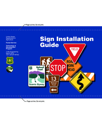
Page cut line. Do not print.United StatesDepartment ofAgricultureForest ServiceTechnology &DevelopmentProgramSign InstallationGuide7100–EngineeringMarch 20101071-2812P-MTDCROADWORKAHEADScenic BywayPage cut line. Do not print.
NoticeThis document is disseminated under the sponsorship of the U.S. Department of Transportation in the interest of information exchange. The U.S. Government assumes no liability for the use of information contained in this document.The U.S. Government does not endorse products or manufacturers. Trademarks or manufacturers’ names appear in thisreport only because they are considered essential to the objective of this document.The contents of this report reflect the views of the authors, who are responsible for the facts and accuracy of the data presented herein. The contents do not necessarily reflect the official policy of the U.S. Department of Transportation.This report does not constitute a standard, specification, or regulation.ROADWORKAHEADScenic Byway
Page cut line. Do not print.Thanks to:Steve Coupal—R-2Mike Tippie—R-6Fred Ranck—FHWAVictoria Brinkly—FHWAThis publication is a result of a partnership between the U.S.Depar tment of Agriculture (USDA), Forest Ser vice,Technology and Development Program and the U.S.Department of Transportation, Federal Highway Administration(FHWA), Coordinated Technology Implementation Program(CTIP). CTIP is a cooperative technology deployment andsharing program between the FHWA Federal Lands Highwayoffice and the Federal land management agencies.The Forest Service, United States Department of Agriculture (USDA), has developed this informationfor the guidance of its employees, its contractors, and its cooperating Federal and State agencies, andis not responsible for the interpretation or use of this information by anyone except its own employees.The use of trade, firm, or corporation names in this document is for the information and convenienceof the reader, and does not constitute an endorsement by the Department of any product or serviceto the exclusion of others that may be suitable.The U.S. Department of Agriculture (USDA) prohibits discrimination in all its programs and activitieson the basis of race, color, national origin, age, disability, and where applicable, sex, marital status,familial status, parental status, religion, sexual orientation, genetic information, political beliefs,reprisal, or because all or part of an individual’s income is derived from any public assistanceprogram. (Not all prohibited bases apply to all programs.) Persons with disabilities who requirealternative means for communication of program information (Braille, large print, audiotape, etc.)should contact USDA’s TARGET Center at (202) 720-2600 (voice and TDD). To file a complaint ofdiscrimination, write to USDA, Director, Office of Civil Rights, 1400 Independence Avenue, S.W.,Washington, D.C. 20250-9410, or call (800) 795-3272 (voice) or (202) 720-6382 (TDD). USDA isan equal opportunity provider and employer.Page cut line. Do not print.Sign InstallationGuideROADWORKAHEADScenic BywayDonna SheehyTraffic Management EngineerTed J. CoteVisual Information SpecialistUSDA Forest ServiceTechnology and Development ProgramMissoula, MT6E62H99—Sign Installation Field GuideMarch 2010
ContentsIntroduction. . . . . . . . . . . . . . . . . . . . . . . . . . . . . . . . . . . . . . . . . . . . . . . . . . . . . 1Placement Guidelines . . . . . . . . . . . . . . . . . . . . . . . . . . . . . . . . . . . . . . . . . . . . . . . . . . . . . . . . . . . . . . . . . . . . . . . . . . . . . . . . . . . . . . . . . . . . . 2Breakaway Guidelines for Wood Sign Posts. . . . . . . . . . . . . . . . . . . . . . . . . . . . . . . . . . . . . . . . . . . . . . . . . . . . . . . . . . . . . . . . . . . . . 4Wood Sign Post Spacing and Size Requirements. . . . . . . . . . . . . . . . . . . . . . . . . . . . . . . . . . . . . . . . . . . . . . . . . . . . . . . . . . . . . . . 5Sign Face Orientation Angle . . . . . . . . . . . . . . . . . . . . . . . . . . . . . . . . . . . . . . . . . . . . 6Sign Decals. . . . . . . . . . . . . . . . . . . . . . . . . . . . . . . . . . . . . . . . . . . . . . . . . . . . . . . . . . . . . . . . . . . . . . . . . . . . . . . . . . . . . . . . . . . . . . . . . . . . . . . . . 7Regulatory Sign Installations. . . . . . . . . . . . . . . . . . . . . . . . . . . . . . . . . . . . . . . . . . . . . . . . . . . . . . . . . . . . . . . . . . . . . . . . . . . . . . . . . . . . . 8Warning Sign Installations . . . . . . . . . . . . . . . . . . . . . . . . . . . . . . . . . . . . . . . . . . . . 10Object and Barricade Marker Installations. . . . . . . . . . . . . . . . . . . . . . . . . . . . . . . . . . . . . . . . . . . . . . . . . . . . . . . . . . . . . . . . . . . . . . 16Guide Sign Installations. . . . . . . . . . . . . . . . . . . . . . . . . . . . . . . . . . . . . . . . . . . . . . . . . . . . . . . . . . . . . . . . . . . . . . . . . . . . . . . . . . . . . . . . . . 22Delineator Installations . . . . . . . . . . . . . . . . . . . . . . . . . . . . . . . . . . . . . . . . . . . . . . 33ROADWORKAHEADScenic Bywayii
Page cut line. Do not print.IntroductionIt is very important to install standard traffic control signs consistently andcorrectly. The effectiveness of a sign can be compromised if it is used inappropriately or if it is installed incorrectly. A sign that is confusing, or one thatcannot be seen in time, is useless.Uniform installation of signs is highly desirable. However, because no tworoads are exactly alike, unusual situations may be encountered relating totopography, man-made objects, intermediate intersections, or other circumstances that may require some modifications to typical sign placementguidelines and standards. The most suitable placement of each sign mustbe determined at the site—where all variables are visible. Any deviations oradjustments should be documented.This guide contains information needed to install traffic control signs onNational Forest System roads in accordance with the “Manual on UniformTraffic Control Devices” (MUTCD) and EM 7100-15, “Sign and PosterGuidelines for the Forest Service.” The guide provides a visual reference forcontractors, volunteers, and Forest Service field personnel who install andmaintain signs. A quick check of the guide should ensure far fewer errors ininstallations.State and county sign requirements may vary. Check with local jurisdictions when installing signs on county, State, or Federal roads. The ForestService has no authority to install signs of any nature within the right-of-wayof county, State, or Federal roads without a signed agreement from theauthorizing agency.Before any signs are ordered and installed, this guide assumes that: A sign plan has been completed and approved. An engineering study or engineering judgment has been used to determine sign needs. All traffic control signs, messages, and sizes meet MUTCD and ForestService standards.The guide is not intended to serve as a substitute for training nor does itinclude every type of sign. Refer to the “Manual on Uniform Traffic ControlDevices” (MUTCD) and EM 7100-15, “Sign and Poster Guidelines for theForest Service,” for complete information.1Page cut line. Do not print.
Page cut line. Do not print.Placement GuidelinesLocate signs on the right side of the road unless specificstandards require otherwise.Place signs where they are clearly visible and provide adequatetime for proper viewer response. Consider factors such as vehiclespeed, road conditions, intermediate intersections, sight distance,and alignment. Select locations that minimize viewing obstructions.Avoid locations such as: Dips in the road Just beyond the crest of a hill Where a sign could be obscured by other signs or objects Where the sign may interfere with the normal use of the road Where there is increased need for users to focus on the road Where vegetation could cover the sign Snow removal and disposal areasCertain signs supplement each other and are mounted on thesame post, such as: A warning sign with an advisory speed plate (page 14) Route markers and destination signs (pages 22 to 25)Some signs should not be mounted together. Signs with different messages should be erected individually on separateposts, such as: A speed limit and a one-way sign A curve warning sign and a junction-ahead sign A warning sign and a guide signSign SpreadingSeveral signs at the same location can overload users with too much information,causing confusion and detracting from critical messages. Signs requiring differentdecisions should be spaced sufficiently far apart for the required decisions to bemade independently and safely. To determine the minimum spread distance betweensigns, use table 1.Table 1—Minimum spread distance (distance between signs) for the speed posted.If the speed limit is not posted, an engineering traffic study should be conducted todetermine the 85th percentile speed (normally considered the highest safe speedfor a section of roadway). The sign spread is based on the 85th percentile speed.SpeedMinimum Spread Distance 35 miles per hour100 feet 40 miles per hour5 x the speed feetIn situations where two or more signs are needed at about the same location, use thefollowing placement order:1. Location-critical regulatory signs, such as STOP and YIELD2. Location-critical warning signs, such as TURN and INTERSECTION3. Other regulatory or warning signs, such as SPEED LIMIT or LIVESTOCK4. Route markers and guide signs5. Other informational signs2Page cut line. Do not print.2
Page cut line. Do not print.Placement Guidelines (cont.)Lateral OffsetMounting HeightLateral offset is the distance from the edge of the traveled way to the nearestedge of the sign—not the distance to the sign post.1. On conventional roads, use:a) A minimum of 12 feet from the edge of the traveled wayb) Where the shoulder is wider than 6 feet, a minimum of 6 feet from theedge of the shoulderc) No less than 2 feet where it is impractical to follow a or b2. On roads where signs are placedbehind barriers such as curbs orguardrails, use:a) A minimum of 2 feet from theroadside edge of the barrierLateraloffset*Mounting height is measured from the road surface to the bottom ofthe sign.Primary SignUse a minimum of 5 feet in: Rural areasUse a minimum of 7 feet in: Areas with parking or pedestrians Urban, business, commercial, or residential areas Areas where the view of the sign may be obstructedNARROWSTEEPROADSupplemental plaque orsign3. On low-volume roads (fewer than 400vehicles per day) with no shoulders,use:a) A minimum of 12 feet where terrainand vegetation permitb) A minimum of 2 feet where terrainor vegetation make it impractical tofollow aSupplemental plaques or signsmay be 1 foot lower than theminimum mounting height forthe primary sign.Edge oftraveled wayAllow a 1-inch gap betweenstacked signs so they canexpand and contract.* Follow lateral offsetguidelines 1, 2, or 3.If a sign is installed within the clear zone, a breakaway sign post shall beused (see page 4). The clear zone is the area that ideally would be clear ofobstacles that might be a hazard to a vehicle that left the road. The width ofthe clear area depends on traffic volume, vehicle speed, and the terrain.Page cut line. Do not ue or signN EXT7 MI LES*****Road surface** Mounting height for primary signs*** Mounting height for supplementalplaques or signs3
Page cut line. Do not print.Breakaway Guidelines for Wood Sign PostsSign postDirection of travelDireCL18 inB*TBreakawaydistanceGround lineBreakawayholes18 in4 innoftraBreakaway holes must beperpendicular to the directionof vehicle travel.Dimension T is parallel to thedirection of vehicle travel and isthe larger of the dimensions.lAfter installing the sign post,drill the breakaway holes andtreat holes with preservative.See chart for hole diameter.For T dimensions notshown on chart, use T/3,rounded up to the nearest1 2 in.Typical Hole Spacing Detail4 inBreakaway Design RequirementsDPost size(in)Holediameter(in)Dminimumburial depth(ft)Bminimum breakawaydistance(ft)4 by 44 by 66 by 66 by 8—1.5233444——77DTypical Breakaway Support*All posts closer than 7 feet from each other act together. Install nomore posts than allowed within 7 feet of each other so the combination of posts meets the breakaway guidelines.ioveTBreakawayholesctAll wood posts 4 x 6 and largermust be modified to meetbreakaway requirements if theyare within the clear zone.4Page cut line. Do not print.4
Page cut line. Do not print.Wood Sign Post Spacing and Size RequirementsMax. width1 8Width3 8WidthMax. widthMax. width3 8Width1 8Width1 5WidthThree-Post Spacing*(Nonbreakaway installation)1 5WidthTwo-Post Spacing**Post spacing applies to both wood and steel posts.**For sizes of steel posts, refer to EM 7100-15, chapter 3c.***The maximum width is 36 inches for diamond-shaped signs.PostSize**(in)Nonbreakaway sign posts should be installed outside theclear zone, behind a guardrail, or behind a nontraversable ditch.5Page cut line. Do not print.3 5WidthSingle-PostOne postTwo postsMax.width(in)Max. signarea(sq. ft)Max.width(in)Max. signarea(sq. ft)4 by 448***10724 by 64820726 by 6482096Three postsMax.width(in)Max. signarea(sq. ft)209630501447595——
Page cut line. Do not print.Sign Face Orientation AngleSigns are mounted at approximately rightangles to oncoming traffic. It may be necessary to rotate a sign slightly off 90 degreesto avoid glare reflecting off the sign facedirectly into the driver’s eyes.Traffic directionAn angle of about 93 degrees to the line ofapproaching traffic is recommended.93 On curves, orient the sign to face the oncoming traffic—not the road edge.On steep grades, it may be necessary totilt the sign forward (uphill grades) or back(downhill grades) to make it easier formotorists to read.Traffic direction93 6Page cut line. Do not print.6
Page cut line. Do not print.Sign DecalsWhen they are first installed, all signs should have the installation date and vandal warning decals attached to the corner of the sign closest to the road.The vandal warning decal goes on the back of STOP or YIELD signs, but on the front of all other signs. The installation date decal goes on the back ofall signs.Both decals may be obtained from Unicor.Sign installationdate decal2 0 0 1YEAR123456INSTALLATION7DATE89 MONTH10 11 1221234567890Vandal warningdecalTHE WILLFUL DEFACING ORREMOVAL OF FOREST SERVICENOTICES SUBJECT TO CRIMINALPROSECUTION WHICH MAYRESULT IN A FINE AND/ORIMPRISONMENT1 USC S. 1 1 10,000 FINE AND/OR 10 YEARSTypical placement on the front of the sign.Typical placement of the decalon the back of the sign.NATIONANATIONALNA FORESTACCESSAANTELOPE LAKEGuide signsRegulatory signsGuide sign—decal has white legend ontransparent filmWarning signsRegulatory sign—decal has blacklegend ontransparent filmVandal Warning DecalInstallation Date Decal7Page cut line. Do not print.ONEWAYWarning sign—decal has blacklegend ontransparent film
Page cut line. Do not print.Regulatory Sign InstallationsR12-5Regulatory signs: Inform users of traffic laws, regulations, and legal requirements Are enforceable Are placed at the point where the regulation begins5-ft min.**Roadsurface**As close as practical,following the lateraloffset guidelines onpage 3.Edge of traveled way or shoulder***The 5-foot minimum mounting heightapplies only in rural areas. See page 3 forthe mounting height guidelines that applyin other areas.orR1-2Other Regulatory Signs Used onNational Forest System RoadsR1-1Yield and Stop SignsR11-2ONEWAYR2-18R6-1Page cut line. Do not print.8
Page cut line. Do not print.Regulatory Signs for a Low-Volume Rural Road*The 2-foot minimum distance for low-volume roads applies onlywhere terrain or vegetation limit the distance. See page 3 forlateral offset guidelines on other types of roads or where terrainand vegetation are not factors.Page cut line. Do not print.9**The 5-foot minimum mounting height applies only in rural areas.See page 3 for the mounting height guidelines that apply in otherareas.
Page cut line. Do not print.Warning Sign InstallationsWarning signs: Warn drivers of unexpected conditions or situations Indicate need for caution May call for reduced speed or an unexpected vehicle maneuver Are placed in advance of the situation to allow adequate time for proper response considering approach speed,road conditions, intermediate intersections, and other factors as shown in table 2 on page 11225 ftTraffic directionTraffic direction225 ftExampleUsing table 2: 85th-percentilespeed 35 mphMinimum distance fromintersection 225 ftAdvance Warning Sign Placement Distances10Page cut line. Do not print.10
Page cut line. Do not print.Warning Sign Installations (cont.)Minimum Advance Placement DistancesTable 2—Advance warning sign placement distances for unpaved low-volume roads.Posted speed t)2025303540455055115155200250305360425495Distance for deceleration (feet)to advisory speed listed (mph)10203040(ft)Additional distance (feet)on downgrade 50185225whether the placement distances may be reduced. Document calculations and rationale. Distances are for level roadways. Increase placement distance ondowngrades of 3 percent or steeper. Placement distances on upgrades may be reduced by one-half thedistances listed for downgrades. On conventional roads and paved low-volume roads (fewer than 400vehicles per day), use the MUTCD. These minimum distances may be exceeded when necessary. Distance for deceleration is the minimum distance a warning signshould be placed in advance of a condition. Sign placement distances are based on sign legibility for 24-inchsigns and 4-inch letters. If larger signs are used, evaluate the placement distances as partof the engineering study or use engineering judgment to determine11Page cut line. Do not print.————275300375450
Page cut line. Do not print.Warning Sign Installations (cont.)Not less than2 ft fromedge oftraveledwayRoadsurfaceNot lessthan2 ftHEAVYTRUCKTRAFFICNot lessthan 12 ft*NARROWSTEEPROADN EXT7 MILESGuardrailor curb5 ft**5 ft**4 ft***Edge oftraveled wayRoadsurface5 ft***See page 3 for lateral offset guidelines that apply to roads with shoulders or where the 12-footminimum is not practical.**The 5-foot minimum mounting height applies only in rural areas. See page 3 for the mountingheight guidelines that apply in other areas.***See page 3 for the mounting height of supplemental plaques or signs and for therecommended gap between stacked signs.Low-Volume Rural RoadsWhere Terrain or VegetationAll Rural Roads—Limit the Lateral OffsetStandard PlacementRural Low-Volume andConventional RoadsLateral Offset and Mounting Height for Warning Signs12Page cut line. Do not print.12
Page cut line. Do not print.Warning Sign for Low-Volume Rural Roads(no supplemental plaques)*The 2-ft minimum distance for low-volume roads applies onlywhere terrain or vegetation limit the distance. See page 3 forlateral offset guidelines on other types of roads or where terrainand vegetation are not factors.Page cut line. Do not print.13**The 5-foot minimum mounting height applies only in rural areas.See page 3 for the mounting height guidelines that apply in otherareas.
Page cut line. Do not print.Warning Sign With Advisory Speed Plate for a Conventional orLow-Volume Rural RoadAdvisory speed plates supplement the warning sign and shall notbe used alone.**The 5-foot minimum mounting height applies only in rural areas.See page 3 for the mounting height guidelines that apply in otherareas.***See page 3 for the mounting height of supplemental plaques orsigns.*See page 3 for lateral offset guidelines on other types of roads orwhere terrain or vegetation limit the distance.14Page cut line. Do not print.14
Page cut line. Do not print.Warning Sign With Advisory Speed Plate and Supplemental Plaque forConventional or Low-Volume Rural RoadsAdvisory speed plates and supplemental plaques are not to be usedalone. They shall be used only to supplement a warning sign.*See page 3 for lateral offset guidelines on other types of roads orwhere terrain or vegetation limit the distance.Page cut line. Do not print.**See page 3 for the mounting height of supplemental plaques orsigns.15
Page cut line. Do not print.Object and Barricade Marker InstallationsType 3 object markers are used to mark objects that intrude into or constrict the roadway.Single-lane roadTraffic sideNotes:1. Stripes slope downwardtoward the side of theobstruction on whichtraffic is to pass.Traffic side3-in min.Bridge rail endInner edge ofmarker in linewith inneredge of theobstructionRoad surface4 ft*2. For a bridge with arailing but no curb, markthe inner edge of therailing.Curb orhazardousobstructionto be markedEdge oftraveled way8 ftor lessType 3objectmarker4 ft*Road surfaceGround*Vertical mounting height may vary according to need. Mounting height isnormally 4 feet, but shall be no less than 6 inches.Placement of Type 3 Object Markers16Single-Lane RoadWith Narrow BridgePage cut line. Do not print.16
Page cut line. Do not print.Bridge Signing With Type 3 Object Markers(to mark objects that intrude into or constrict the roadway)Option: Type 1 object markers also may be used to mark objects that intrude into or constrict the roadway. For a bridge with a railing but no curb, mark the inner edgeof the railing.17Page cut line. Do not print.
Page cut line. Do not print.Type 2 Object Marker InstallationsType 2 Object Markers are used to mark objects that are outside the roadway, but close enough to present a hazard. For narrowobjects, such as cattleguards, object markers may be mounted back to back on the same post.RoadAlternate locationObject markers mounted back to backObject Marker Locations on a CattleguardModified Type 2Object Marker18Page cut line. Do not print.18
Page cut line. Do not print.Modified Type 2 object marker shownCattleguard Signing With Type 2 Object Markers(roadway is not constricted)*Vertical mounting height may vary when an object requires a lower or higher mounting. Mount at least 6 inches above the road surface.19Page cut line. Do not print.Inner edge ofmarker in linewith inner edge ofthe obstruction.
Page cut line. Do not print.Gate Sign InstallationBMType 2 OMMin. 32 to 42 inMin. 32 to 42 inTraveled wayOne-lane roadOM4-1, 2, or 3Type 2 OMMin. 32 to 42 inMin. 32to 42 inOne-lane roadBarricade Markers (BM), Type 2 Object Markers (OM),and End-of-Roadway Markers (OM4-1, 2, or 3) Used on GatesTypeTypeIf motorizedor nonmotorized use (such as bicycles) occurs behind a gate, the back side may require signing also. The size of barricade markersSecuringOMdepends onapproachSecuringspeeds.2 OMpost2post20Edge of roadPage cut line. Do not print.Locking deviceType2 OMPlan viewBMLocking deviceType 2 OMType2 OM20
Page cut line. Do not print.Gate Signing With Object Markers (OM) for One-Lane Roads21Page cut line. Do not print.
Page cut line. Do not print.Guide Sign InstallationsGuide signs: Are placed ahead of the intersection Provide guidanceMilemarkerDestination signNot less than12 ft*Not less than12 ft*DUTCH JOHN 53TRUCKEE232122145-ft min.**Edge oftraveledwayRoutemarkers4-ftmin.***Not less than12 ft*Edge oftraveledway3-ft min.to lowestnumberorEdge oftraveledway4-ftmin.31345-ft min.**orRoad surfaceRoad surface*See page 3 for lateral offset guidelines that apply to roads with shoulders or where the 12-footminimum is not practical.**The 5-foot minimum mounting height applies only in rural areas. See page 3 for the mountingheight guidelines that apply in other areas.***See page 3 for the mounting height of supplemental plaques or signs and for the recommended gap between stacked signs.Lateral Placement and Mounting Height for Guide Signs22Page cut line. Do not print.22
Page cut line. Do not print.Guide Sign Installations (cont.)Table 3—Advance placement of guide signs at intersections. Speeds arerounded off to the nearest 5-miles per hour.Speed limit or85th-percentile Maintenance levelspeed (mph)3, 4, 5 roads (ft)Under 15Maintenance level 2 roads androads within administrativeor recreation sitesAt or near intersectionAt or near intersection15 to 25100At or near intersection30 to 40100 to 200—45 and higher200 minimum—Example using table 3 fora maintenance level 4 road:85th-percentile speed 45 mphRoad maintenance level 4Min. distance 200 ft*Use 25 to 200 feet onunpaved roads orabout 300 feeton paved roads.FOREST BOUNDARY 9ANTELOPE LAKE13FRDMaintenanc e le*vel 4Placement of Guide, Destination,and National Forest Access SignsACCESSANTELOPELAKEorNATIONAL FORESTACCESSANTELOPE LAKEFRDSA**Use table 3 for distances.23Page cut line. Do not print.road**
Page cut line. Do not print.Guide Sign Installations (cont.)TRUCKEE 3KEYSTONE 4210*202DUTCH JOHN 5TRUCKEE3210Allow a 1-inch gap between stackedsigns so they can expand andcontract.NFSR 202Center the sign for the approachinglane of traffic.orNFSR 210*Obtain distance from table 3(page 23) based on the speedlimit or anticipated speed oftraffic on the road.*DUTCH JOHNKEYSTONE21054202Placement for Destination Signs24Page cut line. Do not print.24
Page cut line. Do not print.Destination Sign With Route Markers for Conventional andLow-Volume Rural Roads*See page 3 for lateral offset guidelines on other types of roads orwhere terrain or vegetation limit the distance.**The 5-foot minimum mounting height applies only in rural areas.See page 3 for the mounting height guidelines that apply in otherareas.Page cut line. Do not print.***See page 3 for the mounting height of supplemental plaques orsigns and for the recommended gap between stacked signs.25
Page cut line. Do not print.Guide Sign Installations (cont.)Installation of Route MarkersHorizontalroute marker214Distinctiveroute marker21425 to 100ftNote: Route markers may be installedbelow applicable guide signs as shownon page 24.M1-7M6-725 to 100ft*Use table 3 to determinethe distance based on thespeed limit or anticipatedspeed of traffic on theroad.6 to 12 ftAll FM1-7H*214or214Minor intersectionMajor intersectionLocations for Distinctive and Horizontal Route Markers forMaintenance Level 3, 4, and 5 Roads26Page cut line. Do not print.26
Page cut line. Do not print.Horizontal or Distinctive Route Marker on Low-Volume Rural Roads*The 2-ft minimum distance for low-volume roads applies onlywhere terrain or vegetation limit the distance. See page 3 forlateral offset guidelines on other types of roads or where terrainand vegetation are not factors.Page cut line. Do not print.27**The 5-foot minimum mounting height applies only in rural areas.See page 3 for the mounting height guidelines that apply in otherareas.
Page cut line. Do not print.Guide Sign Installations (cont.)Road surfaceEdge of traveled wayInstallation of Vertical Route Markers2 to 12 ft35Barrier or entrancetreatment3 ft tolowestnumberMaintenanceLevel 1 road25 to 100 ft212Option: Use a delineatorpost with a wood oraluminum sign panel.*25 to 100 ft124FM1-7VMaintenance Level 2 road*Distances may be greater when theentrance is intentionally disguisedto discourage use.Locations for Vertical Route Markers on Maintenance Level 1 and 2 Roads28Page cut line. Do not print.28
Page cut line. Do not print.Vertical Route Marker for Maintenance Level 1 and 2 Roads29Page cut line. Do not print.
Page cut line. Do not print.Trailblazer Assembly for Conventional or Low-Volume Rural Roads*See page 3 for lateral offset guidelines on other types of roads orwhere terrain or vegetation limit the distance.30**The 5-foot minimum mounting height applies only in rural areas.See page 3 for the mounting height guidelines that apply in otherareas.Page cut line. Do not print.30
Page cut line. Do not print.Milepost Marker for Conventional or Low-Volume Rural Roads*See page 3 for lateral offset guidelines on other types of roads orwhere terrain or vegetation limit the distance.Page cut line. Do not print.31
Page cut line. Do not print.Federal Recreation Symbol Assembly for Conventional or Low-Volume Rural RoadsGenerally, no more than four symbols should be mounted on a singlesign assembly.*See page 3 for lateral offset guidelines on other types of roads orwhere terrain or vegetation limit the distance.32**The 5-foot minimum mounting height applies only in rural areas.See page 3 for the mounting height guidelines that apply in otherareas.Page cut line. Do not print.32
Page cut line. Do not print.Delineator InstallationsTravel direction2 to 8 ftfrom theedge ofpavementor 48 inDelineatorsU-postRoad surfaceTop View30 inBidirectional delineatorNotes:1. Colors (as viewed by driver) on two-way roads, including singlelane roads, are white on both sides of the road.On one-way roads, colors are white on the right and yellow on theleft side of the road. (From MUTCD Section 3D.03)2. Delineator posts may be galvanized steel U-posts, 1.12 pounds perlinear foot, 6.5 feet long, or flexible fiberglass posts.3. Reflectors may be fastened to posts using rivets or other suitable,nonremovable fasteners.4. The delineators shall be 4- by 4-inch (silver) crystal on both sides,Type 3 retroreflective sheeting. The delineator housing shall be thebidirectional type.33Page cut line. Do not print.
Page cut line. Do not print.Delineator Installations (cont.)Positioning and 0270300BEnd of curveNotes:1. Prorate distance “
a) A minimum of 12 feet from the edge of the traveled way b) Where the shoulder is wider than 6 feet, a minimum of 6 feet from the edge of the shoulder c) No less than 2 feet where it is impractical to follow a or b 2. On roads where signs are placed behind barriers such as curbs or guardrails, use: a) A minimum of 2 feet from the