Transcription
PREVOST ELECTRICAL SYSTEMSOur coaches have a number of systems that seem mysterious. They are mysteriousonly until we get to know and understand them, at which point we see and appreciatetheir logic and relative simplicity. What follows is an attempt to provide an overviewor a glimpse at the fundamentals of the electrical systems typically found in ourcoaches. It is not an attempt to be a trouble shooting guide or even to explain someof the nuances of the electrical systems but to help the owner to at least be able tounderstand how it all works and how to identify when something is not working.THE CHASSISCommon to all of our coaches is the chassis (Prevost bus) electrical system.An important thing for all owners to recognize is that there is a point at which thechassis and the house electrical systems come together. For the most partconverters limit that merging of the house and chassis to a single point. There aresome exceptions and they will not be covered here because they tend to be converterspecific and proprietary.All chassis electric is DC voltage, both 12 volts and 24. The batteries supplyboth voltages because they are wired such that both voltages can be provided. Ourfour chassis batteries are wired both in series (two 12 volt batteries in series canprovide 24 volts) or in parallel (two 12 volt batteries in parallel provide 12 volts, butthe capacity of 2 batteries). They are charged using an engine driven alternator in allcases. Some coaches are provided with auxiliary chassis battery chargers that arepowered from the generator or shore power. For now we will focus on the alternator.The battery electrical diagram is located on the RH side door.
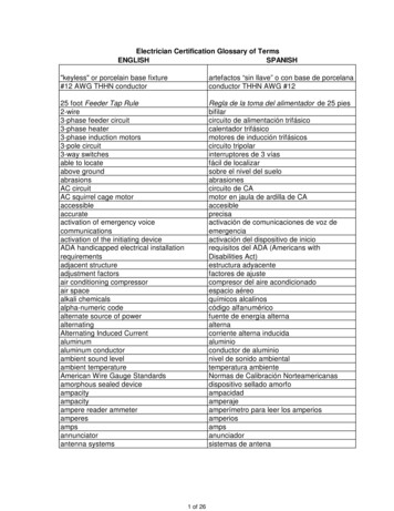
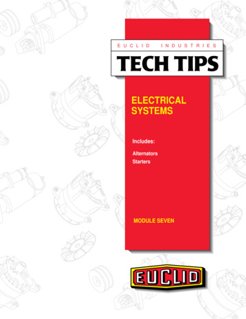
This is a large style alternator supplied with Prevost shells. It can be used as thesingle engine powered battery charging device, or it can be used in conjunction with asecond alternator such as show below.
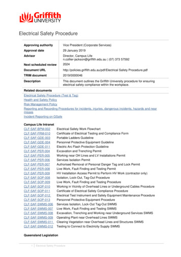
This is a typical second alternator, engine driven. It can be located near the fan drive,or in this case near the chassis batteries.Some coaches have a single alternator. It is typically a large alternator withsufficient power output to handle not only the loads of lighting, AC systems, andbattery charging, but the single alternator will also be used to maintain the charge onthe house batteries. When one alternator is used to charge both the house and thechassis batteries the power from the alternator will pass through some means ofisolating the two sets of batteries so the discharge of one set will not cause adischarge of the other set. That device to keep the two sets of batteries independentof one another may be an “isolator” (clever of someone to name it that) or it may bea device such as a solenoid relay that closes only when the alternator is functioning.It is important to understand the chassis batteries and the house batteries are to beindependent of each other and they are only “joined” electrically when receiving acharge from the engine driven alternator
Two different ways to isolate the house and chassis batteries. Both will not alloweither set of batteries to discharge and pull the other set’s voltage down at the sametime.
Since the bus chassis alternator is 24 volts, and since the batteries are wiredto provide both 12 and 24 volts there must be a means of insuring the batteries arecharged in such a way as to insure a 12 volt load will not pull down some of thebatteries in the set and not others. To accomplish this there is a device that insuresthe batteries receive an equal charge. Based on previous knowledge about how theisolator was named you can safely assume the means of equally charging both the12 and 24 volt battery banks will be via a device called an “equalizer.“ Seeing thatsome of the devices used in our electrical systems have descriptive names likeisolator and equalizer I wonder why the device that charges our batteries is called analternator?
Some coaches have two equalizers, but later model coaches have a single isolatorsuch as the two shown above.Already this is starting to sound complicated, but lets peel back the layers andlook only at the basics. First and most important we need to know when everything isworking and how to verify it. Start with the alternator. Every Prevost owner needs toown a decent quality multimeter and at least have an understanding of how to readvoltages and how to check for open or closed circuits. I am going to assume here that
will be the case. If you are unfamiliar with the use of a multimeter, or a multitesterthis would be a good opportunity to review its manual.It is important for owners to be very clear on the electrical circuits andwhether those circuits are chassis or house. The chassis circuits are associated withthe bus only. They are for exterior lighting such as headlights and brake lights andclearance lights. Other exterior lights such as those that are used to light the areabeneath the awning however would likely be house electrical circuits. The chassiselectrical system will be used to power the engine and transmission computers, thebus heating and AC systems, dash lighting, and the engine starting system. To learnwhat electrical circuits are associated with the chassis the listing of relays, circuitbreakers and wires on the doors of the front and rear electrical compartments is anexcellent source of information.Somewhere in your coach there is a gauge that tells you your chassis voltage.I have no idea how it will be labeled or where it will be. If I were to guess it will notshow a voltage until you turn on the ignition key. With the key on, but the bus notrunning the displayed chassis voltage should be around 24 or 25 volts DC. That isdirect current, not to be confused with alternating current found in the house, suchas for the outlets, or the TV or the microwave. Once you have found the chassisvoltage and it is around the range specified you are verifying your batteries have acharge and everything appears OK. Now start the bus and see the voltage change.With the bus running the chassis battery voltage displayed on the gauge should bearound 27 or 28 volts. Now you have verified the alternator is working. If the voltagedid not rise you have a problem.
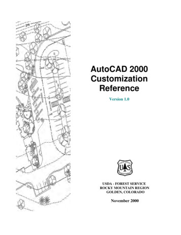
This pair of gauges is located on the dash. The LH gauge shows the chassis voltage(the key is off so no information is displayed), and the RH gauge shows the housebattery voltage. The voltage displayed is approximately 27.2 volts DCYou can do the same system check with your multimeter. Connect the blacklead to a bare metal spot on the chassis. Connect the red lead to a 24 volt post onthe bank of chassis batteries (refer to the wiring diagram on the inside of the RH sidechassis door). Your multimeter used in this fashion is gong to give you precisereadings. The gauge inside the coach may be less precise because there is a currentdrop when the voltage passes through a long run of wire.If your chassis batteries with the coach engine off are anywhere between 24.5volts DC and 25.8 your batteries are likely in good shape. When you start the busengine the voltage should now read between 26.5 volts on the low side to 28.5 voltson the high side. Anything lower or higher is an indication there may be a problem.Keep in mind however these values are for the chassis when the bus is notconnected to shore power or the generator is not running. These are also voltagevalues taken at the batteries with an accurate multimeter. (Note, being connected toshore power or having the generator run may not change the values listed above, butin some coaches the presence of shore or generator power automatically powers a
chassis battery charger.)Already you know what values to expect for your bus or chassis batteries andcharging system. You know what to expect when the engine is not running (and youhave not run down the batteries), and you know that the voltage will increase to adifferent value to indicate the charging system, including the alternator, the isolatorand the equalizer are working. If you compare the multimeter voltage reading takenat the batteries with the gauge reading from inside the coach you will know if there isa difference between the two and you can mentally adjust the inside reading tocompensate for the probable voltage drop.The chassis voltage is something that must be monitored. It is as important asoil pressure or temperature or air pressure. If it is too low you may not be able to startthe coach, or if the coach is running the computers may shut the coach down due tolow voltage. Conversely, voltage that is too high can damage not only the batteries,but it can also damage other devices and possibly create a fire hazard. Personally Iconsider voltages lower than 12 volts per battery (or 24 volts) or higher than 14.3volts (28.6 volts) to be cause for concern. These are my values, and depending onyour coach, your specific type of chassis batteries, and how your coach is set up yourvalues may be a little different.What if the chassis voltage gauge shows a value approaching or out of thelimits of the normal operating range? The answer is simple. Something is wrong. Thefirst action to be taken is to decide if the problem is serious enough to shut down thebus, or if you can safely get the coach to a service facility. Different types of problemsrequire different actions.High voltage is an indication there is a problem with the alternator, or thevoltage regulator if the device is external to the coach. High voltage is dangerous andit requires the alternator rendered inoperative by removing the alternator drive belt,or if the voltage regulator is external, by removing the field wire from the alternator orthe regulator. You cannot and should not continue to allow an over voltage situationto occur.
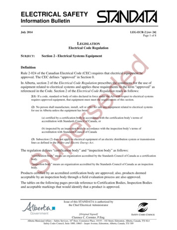
In some cases the coach is equipped with a device such as this monitor that will lightwarning lights on the dash to alert the driver to abnormal chassis electricalconditions. Note, this is not used to monitor the house DC electrical system.Low voltage is an indication you are not charging the chassis batteries, and insome cases it is an indication you are not charging the house batteries also. Let’spresume you notice while driving that the voltage with the engine running is lowerthan normal. The gauge shows the batteries are not receiving a charge. Dependingon the voltage displayed you can drive a considerable distance as long as you canminimize electrical loads on the chassis. For example, if you can drive without lights
or the AC system working you will go much greater distances than if you have to havelights on and the AC system functioning. If you have an auxiliary chassis batterycharger you can maintain a charge by running the generator. But once your chassisvoltage starts to drop below 24 volts you need to consider getting off the road.Many owners have had an alternator or alternator control unit (voltageregulator) fail. If it has not happened in their bus it may have happened in a car, boator plane. As long as the failure is not an over voltage type failure it is usually safe todrive the coach, especially if the coach is equipped with a generator or shore powercharger.When the electric stops in the bus charging system it is sometimes easilyrepaired. As an owner you at least should be able to isolate the problem. If you aregoing to make the repairs yourself or if you are going to arrange for service youshould know what has failed. Start with the obvious and the easy stuff to diagnose orrepair and move towards the more complex causes.If the alternator is belt driven check the belt and check to see the belt is tight.If the alternator has a good belt and the belt is not slipping check to see if thealternator is putting out voltage. Attach the black multitester lead to a good groundand check the voltage at the heavy wire output terminal. If the alternator is notproducing charging current it will be zero volts or close to it at this terminal. If thealternator has voltage at this point go to the next device in line with the red lead onthe multitester (or multimeter, the names being interchangeable). If the coach uses asingle alternator to charge both the house and chassis batteries that next device willbe the isolator. Verify it has current to the center terminal, or the input. If it does,check for current at the house and chassis outputs. If the coach uses a solenoid relaytype of isolator and the solenoid has current at the coil posts (the smaller posts),then check to see if the solenoid has current passing through the relay. If it is passingcurrent it will be at both posts.If you have an external voltage regulator you can further narrow your searchfor the problem. An external voltage regulator typically has a wire called the “field”wire going to the alternator. This wire is the key to regulating the voltage regulatoroutput. In order for an alternator to create voltage, the alternator requires somecurrent input. This current is essential and in the case of completely dead batterieseven if the engine is started the alternator will still not function because there is nopower available to “excite” the windings. A regulator functions by alternatelysupplying power to the alternator windings via the field wire, and when the voltagereaches the set limit, it removes power from the field wire which causes the voltageto drop back within range, at which point it builds until it exceeds the set point andthe regulator again removes field wire current.
This is an external alternator voltage regulator. Some are smaller and have adifferent appearance. Some are internal to the alternator and are not repairable oradjustable.This alternating application and removal of power to the field wire happens sofrequently it appears the voltage is a constant. To determine if the cause of anapparent alternator failure is the regulator or the alternator, disconnect the field wirefrom the regulator, and either directly or using a short jumper connect the field wiredirectly to the 24Volt post of the chassis batteries. If the alternator is functioning youwill note the engine (which must be running) will lug slightly, but perceptibly, and the
voltage to the batteries will begin ramping up and will be able to go higher than thesafe range. By hooking the alternator field wire directly to a 24Volt power sourcesuch as the batteries you have created an unregulated power supply. Monitor thealternator output at the 24 volt battery posts using your multimeter. Obviously eitherdisconnect the wires or shut the engine down as soon as it is determined thealternator is capable of creating voltage. Failure to do so could result in damage tothe batteries and chassis electrical components.If voltage goes up using this method the regulator has failed, and if it does notthe alternator has failed.THE HOUSELike the chassis the house portion of the conversion uses another set ofbatteries as part of the house electrical system. The batteries may share a chargingalternator with the chassis, or the chassis and the house may have dedicatedalternators. Each converter has a different approach to charging the house batteriesand some use the single chassis alternator, and some use a dedicated alternator tocharge the house batteries. Often the house batteries are charged using a smalleralternator, but not always. There is no standard and as an owner you should make aneffort to learn which alternator charges the house batteries and which charges thechassis batteries. Merely guessing is not an acceptable way to make thedetermination. The reason for determining how the house batteries are receivingtheir charge is to make trouble shooting when the time comes easier. Once you know(on a two alternator bus) which alternator supplies power to the house the troubleshooting steps are the same as for the chassis.Unlike the chassis batteries which may not have a separate means ofcharging, the batteries when the engine is not running, the house batteries willalways have an alternate means of maintaining a charge. Whatever device is used formaintaining a charge on the house batteries, it will require a connection to shorepower or it will require the generator to be operating. On some coaches the housebattery charging system is automatically operational and on some the owner has tomanually engage switches to engage the chargers.Older vintage coaches (preceding the early nineties) usually usedcharger/converters and the owner had to manually select the available power source.The power to the chargers was then switched on, usually via a circuit breaker in the120 volt AC electric panel. (For those not familiar with the difference between 120volt AC electric power and the 12 or 24 volt DC electric power discussed previously,think of 120 volt AC power as the electric used in our homes. When we plugsomething into an outlet, such as a lamp or the TV or a small appliance that is the
electricity used. The 12 or 24 volt DC power we have been discussing is low voltagedirect current power and it is a higher voltage version of the type of electric powertypically found in a flashlight. The two types of electric power are never mixed usuallyhaving even their wires isolated from one another. There are a few devices that canoperate on DC and AC power, such as some small TV sets designed to operate onbatteries or plugged into a wall outlet, usually through an adapter.)Later model coaches use automatic transfer switches which recognize theavailability of AC power sources and automatically select the source to use based ona priority established by the converter. For example, in the absence of shore orgenerator power sources a typical coach automatically creates 120 volt AC power forthe various house devices such as the refrigerator, outlets, the TV, etc by convertingbattery DC voltage to 120 volt AC power by means of inverters. Inverters, in theabsence of 120 volt AC input power (such as shore or generator power) automaticallyconvert the available battery power to 120 volt AC current.Inverters have different appearances and are located in various places in the coach.Some are accessible by opening a bay door, and others are hidden behind panels orunder cabinetry. The inverter shown is a combination inverter/charger which hasbecome the most common type.But when those same inverters are provided with 120 volt AC input power,they cease converting the electrical current, and pass that input power into a battery
charger section of the inverter to restore or maintain fully charged house batteries,and they also automatically provide output power by instead passing the inputvoltage directly to the loads stated above. A transfer switch senses the presence ofshore or generator power and no action is required by the owner.As an owner it is important to monitor the house systems. The first priority isto verify the house batteries are being charged or maintaining a charge. When thecoach engine is not running and the coach does not have electrical input from shorepower or generator the house batteries are expected to be within a range of 12 voltsto 12.7 volts (or 24 to 25.4 volts). When the coach has input to the inverters orchargers the expected voltage range will be 13 plus volts (or 26 plus volts). The lackof specificity here is because house batteries can be wet cell, AGM, or Gel cell andeach different type has its own range of acceptable voltages.It is necessary to insure the house batteries are charged and maintained inaccordance with the manufacturer’s specifications. Here are some excellent sites tolearn about your specific type batteries:http://www.windsun.com/Batteries/Battery teries.com/charging procedures.phpWhen monitoring the house battery state of charge it needs to be recognizedthat the voltages are going to vary and that as long as you keep the voltages wellwithin the range specified by the battery manufacturer everything is working asdesigned. When the coach was converted the house battery charging system wasbuilt for the types of batteries originally installed. Years ago the only type of batteryinstalled in our coaches was the conventional wet cell lead acid battery. Newercoaches were equipped with AGM or Gel cell batteries, and their charging systemswere set up for the charging protocols and voltages those types of batteries required.To get the maximum battery life it is important for an owner to verify the converters orinverters are set to properly charge the specific house batteries that are installed.When monitoring the house battery voltages note that the range of voltages observedis within an acceptable range for the type battery installed.But what if the voltages are on the low end of the scale and dropping eventhough the coach is connected to shore power or the generator is running? Theproblem may relate to the loads on the batteries. Are the loads greater than theability of the chargers to maintain battery voltage? Shed load to see if the batteryvoltage starts to increase. If it does increase it may be possible one of the (generally)two chargers is not functioning. Turn off the chargers one at a time. If one of the twochargers is not functioning a voltage drop on the house batteries will be noted.Generally speaking it is a good practice to occasionally verify the proper
operation of the house battery chargers by alternately turning one then another off soif one has failed you will be aware of it before the loss of a charger becomes a crisis.It is recommended that like the chassis batteries you monitor the house batteryvoltages at the battery posts using a good quality multimeter and compare thereadings with the readings shown inside the house at the house battery voltagegauge.By monitoring voltages, and alternately cycling chargers or inverters on and offand verifying voltage readings at the house batteries you are going to be aware of afailure, and what has likely failed. However, before repairing or replacing chargers orinverters it is worthwhile to check battery post connections to insure they are cleanand tight. Lastly, before sending off that inverter check the batteries individually toverify they have not failed and that they are not falsely indicating the charging systemhas failed.CHECKING BATTERIESToday there are some great products available that are light and easy to useto verify the condition of batteries. This is just one ehouse/ATM-SB-300.htmlA search of the web will find many others that can easily be carried in the coach. Abattery can also be tested without a tester. I have charged batteries in a set, andthen disconnected the cables so they are isolated electrically from one another. Afterseveral hours with no load and no connection to other batteries I check the voltagesof each battery individually. Good batteries will be at about 12.7 to 12.8 volts andthey will hold that voltage for days. A battery that starts losing voltage almostimmediately is almost sure to be bad.If a battery tests bad it is probable that it is also pulling down the otherbatteries in the house or chassis groups. Batteries can fail due to age, but also dueto lack of maintenance or failure to observe the proper charging procedures. Isuggest that anytime a battery tests bad, especially if it is less than five years old theentire charging system should be checked to verify it is charging batteries accordingto the requirements of the battery manufacturer.When a battery has failed it generally means the entire set has to be replaced.Replacing a single battery in a multiple battery set often leads to other problems andcreates issues with charging the batteries equally.AC CIRCUITS
AC current (or alternating current) is the type of power we get from shorepower or when we run our generator. It is not to be confused with battery powerwhich is direct current. Our AC power is typically 120 volts although there may besome circuits that are 240 volts AC.Somewhere within our coaches is a display or a gauge that shows the ACvoltage. The standard for an acceptable range is 120 volts, plus or minus 10%. Thatmeans we could see a voltage reading as low as 108 volts, or as high as 132 volts.Neither end of the so called acceptable range is really good, but since the electricindustry has set the standards, that is the range we have to learn to live with. Withshore power we have to accept what we get within that range. Our generator orinverters however should provide 120 volt power much closer to the nominal voltage.If not they should be adjusted by a technician to an acceptable level.This house 120 volt AC panel shows that the incoming shore power is at 117 volts,and the load on the leg shown is 36.9 amps. Although it cannot be seen due to thequality of the photo, the status light shows this power is shore power on the port side.Our inverters have a limited power output expressed in watts. An inverter with
a 2500 watt rating can supply up to that wattage continuously. As an adjunct to thevoltage display, the house AC electrical panel should also display the load expressedin amps. An ampere is a function of the watts divided by the voltage. It soundsscientific, but for nominal voltages of 120, each 120 watts equals an amp. A 1200watt device will draw 10 amps. If the voltage is higher than 120 volts the amperagewill be a little less and if the voltage is lower it will draw a little more amperes. That isan important concept to understand because at lower voltages the amperage loadsincrease. The reason for this understanding is to be able to manage you power.Since everything in our coach or associated with our coach has limits, it will benecessary to manage power consumption. For example, if dry camping and notrunning the generator, the maximum available 120 volt AC power is limited by theinverter rating (and battery capacity). If you have two 2500 watt inverters and theinverters supply the house outlets, the TV, the refrigerator, an auxiliary aircompressor, the water pump, and a trash compactor you have 5000 watts or 41.6amps available. If the refrigerator uses 7 amps (840 watts) and the TV uses 5 amps(600 watts) you have roughly 3500 watts or a little over 29 amps still available.So far so good. But what if you plug in a 2000 (16.6 amps) watt coffee maker,start to take a shower which kicks on a 10 amp water pump, and the auxiliary aircompressor which uses 7 amps starts to run? You have just exceeded your availablepower by a wide margin and something has to shut down. Monitoring the loadsbecomes second nature after a while, but until you reach the point where youintuitively know what loads to turn off when the power available is limited it isworthwhile to record the load for each device and consider if you have the poweravailable for the load before you turn on the switch or device. Every coach has “keyoff” or phantom loads. These are current drawing devices that are out of sight or outof mind. You as an owner can determine what they are by turning every 120 volt ACcircuit off, leaving the house battery chargers (inverters) on, and once the housebatteries are fully charged, note the current draw in amps. On my coach it is about 3amps. This value has to be taken into consideration when managing your availablepower.But what if you are connected to shore power? Depending on the circuitcapacity you could be connected to 20 amp, 30 amp or 50 amp service. These areindustry standard descriptions, but they are confusing. 20 amp service is theavailability of 20 amps (2400 watts) of 120 volt AC power. 30 amps service is theavailability of 30 amps (3600 watts) of 120 volt AC power. So far that seems to makeperfect sense.However 50 amp service is actually two 50 amp (6000 watt) 120 volt ACcircuits for a total of 100 amps of 120 volt AC power. But wait. There’s more. The
circuit breakers rated at 20, 30 and 50 amp are only required by the electricalstandards to handle a continuous load of 80% of their rated capacity, or 16 amp, 24amp or 40 amp. So when you are connected to shore power keep in mind that youcan safely consume power up to the 80% value of the breaker. Beyond that, if thebreaker does not trip consider it a bonus.Even if we have 50 amp service shore power available, and even if thebreakers do not trip until a continuous 50 amp load (per leg) has been applied westill need to manage our electrical loads to insure we do not exceed the shore powerlimits. A coach with four air conditioners, a hot water heater, inverter chargers pullinga heavy load, a refrigerator, an aux air pump, and the TV’s turned on can easilyexceed the available shore power. The loads I described above, even if perfectlybalanced would add up to about 45 amps per leg. If I wanted a cup of coffee orwanted to grill some hot dogs or my wife wanted to use a hair dryer we would trip thecircuit breakers. So again, like when using inverters we need to be aware of the loadsand to observe the amperes as well as the voltage.The running of the generator is the largest source of electric power. In mycoach I have a maximum capacity of 12,000 watts on shore power, but I have a20,000 watt capacity on the generator. My energy management concerns almostdisappear when I am running the generator. The house 120 volt AC electrical systemis quite reliable, and as an owner your main concerns will be understanding the limitsdepending on your power source.INVERTERSThere is no standard relative to how a converter sets up the electrical systememploying inverters. To add to the lack of uniformity there are numerous models ofinverters used. An owner needs to develop an understanding of three things relatingto his inverters. The first and most critical is understanding is what devices are oneach inverter circuit, and the capacity of the inverter powering those devices. Forexample an inverter can have a 3500 Watt rating and it may have an air conditioner,a refrigerator and som
PREVOST ELECTRICAL SYSTEMSPREVOST ELECTRICAL SYSTEMS Our coaches have a number of systems that seem mysterious. They are mysterious only until we get to know and understand them, at which point we see and appreciate