Transcription
Planning and Design GuideFOD-Utilities High Voltage9/24/2014
PLANNING and DESIGN GUIDE final.docxSeptember 2014Table of Contents1Introduction . 41.1Campus Planning . 41.2BDS Requirements and Basis . 41.3General Design Criteria . 41.4Detailed Design Criteria . 41.5Authority Having Jurisdiction . 41.6Design Control. 62Organization and Maintenance . 83Bulk Power Planning Study . 84Distribution System Planning Study . 85Design Process . 8675.1Introduction . 105.2Control Plan. 155.3Parallel Processes . 175.4Design Control (Construction process) . 205.5Drawing Control . 205.6Software Control . 235.7Information Storage and Retrieval. 245.8Electrical Equipment Specification and Selection . 24Testing, Sight Check-out and Pre-Operational Testing . 266.1Introduction . 266.2Factory Testing . 276.3In Process Testing. 286.4Pre-Operational Testing and Commissioning . 286.5Staffing and Staff Qualifications. 286.6In-Process Construction Testing . 286.7Construction Third Party Check-out. 286.8Liaison with Local Utilities and ODIC. 296.9Configuration Management. 29Exposition of General Design Criteria (BDS) . 29The Ohio State University, FOD – Utilities, UTHVSPage 1 of 186
PLANNING and DESIGN GUIDE final.docxSeptember 2014897.1General system design criteria are as follows: . 297.2Supplemental Design Criteria . 33Designing for a Safety Culture . 438.1Designing for Safety . 438.2Introduction: . 438.3Constructability . 448.4Operability . 448.5Maintainability . 458.6Reliability. 478.7Safety and Risk Awareness/Avoidance . 488.8Design Margin . 49Detailed Design Criteria . 499.1Main Transformers. 499.2Main Switchgear . 549.3Standby Generation Paralleling Gear. 599.4Primary Switchgear . 749.5Unit Substations . 879.6Line Reactors . 889.7MV Cable . 909.8Primary Metering . 919.9DC Battery Systems . 929.10Standby Power Systems . 959.11Relay Protection . 989.12Fusing Strategies . 1109.13Low Voltage AC Distribution . 1119.14Grounding Systems . 1149.15Switchgear Control. 1169.16Motor Control . 1199.17Motors. 1229.18Valve Control. 1269.19Control hierarchy . 1299.20Annunciators and Annunciation . 130The Ohio State University, FOD – Utilities, UTHVSPage 2 of 186
PLANNING and DESIGN GUIDE final.docxSeptember 20149.21Relay logic . 1329.22Potential Transformers and Current Transformers . 1379.23PLC application . 1399.24Failure Modes . 1469.25Failure Analysis . 1479.26Power Dependencies . 1489.27Cable Systems, Tray and Conduit . 1499.28Duct Bank Design . 1509.29Manhole (Vault) Design . 1549.30Equipment Enclosure Design (Small, Medium, Habitable) . 1569.31System Voltage Regulation . 1629.32LTC Control . 1639.33CAP Bank Design and Control . 1659.34MV Facility and Equipment Rodent and Pest Control . 1679.35UPS Systems . 1689.40HMI Design and Labeling . 1709.41Feeder Pair Design . 1719.42Third Feeder Design . 1739.43Design of Primary Services, RFI Application Rules . 1749.44Aggregation of Switching Points . 1789.45Utility Communications System . 185The Ohio State University, FOD – Utilities, UTHVSPage 3 of 186
PLANNING and DESIGN GUIDE final.docxSeptember 2014Planning and Design Guide1 Introduction1.1 Campus PlanningTo be effective, planning for the MV Distribution System needs to be an ongoing process integral withthe schematic design of all electrical infrastructure modifications and additions. It is not enough to justhave a plan. That plan needs to be relied upon to direct MV system activity, and regulate system growthand be reflected in the choice of design options. If and when the plan needs to be changed oraugmented to address changes in campus growth patterns or administrative policy, the appropriatechanges need to be documented, and the plan re-issued.1.2 BDS Requirements and BasisDivisions 33 and 48 of the Building Design Standards generally give direction to the organizations thatdesign and construct Utility facilities on Campus. They are not intended to provide project specificdetailed design, except where needed to maintain the design integrity of the MV electrical system as awhole. In some places they touch on the basis and rational for following BDS requirements. In general,they are not a detailed design manual. This document is provided to fill this gap and provide a detailedbasis for adhering to recommended practices at both a system and a component level of design. Wherethis document supports the need to have a high level of consistency within Utility Electrical system, it isnot meant to stifle innovation or technological growth. It is intended to raise the bar, however.1.3 General Design CriteriaThe BDS contains General Design Criteria. These are high level compliance criteria and are meant toprovide direction to the designer. This document provides a discussion of each of these criteria andsome detail on their application.1.4 Detailed Design CriteriaThere are many design practices and component application rules that can benefit from a detaileddiscussion. The basis may not be immediately obvious and in some instances may even becounterintuitive. This document also provides a break-out by component or system of many of the mostsignificant of these and includes discussion of each in the context of the typical applications on campus.1.5 Authority Having Jurisdiction1.5.1 IntroductionOSU Utilities, as a part of a state entity and operating as a bonafide utility, has jurisdiction over majorportions of the campus electrical distribution system up to and including portions of the individualbuilding primary services. It also, under the Utility Exemption clause of the National Electric Code, hasresponsibility and jurisdiction over the process electrical portions of the campus power plant and chilledwater facilities. It is also responsible to coordinate its inspection activities with the Ohio Division ofThe Ohio State University, FOD – Utilities, UTHVSPage 4 of 186
PLANNING and DESIGN GUIDE final.docxSeptember 2014Industrial Compliance (ODIC) for building services and as a courtesy on non-process portions of the LVdistribution in central chiller facilities operated and maintained by Utilities.1.5.2 Permitting ProcessUtilities uses a permitting process to track and regulate the certifications and inspection of primaryservices to campus facilities. Details of this process are described on FODNET Utilities page forestablishing primary services to Main Campus facilities and construction sights. Adherence to this Policyis key to Utilities functioning as authority having jurisdiction (AHJ) for electrical distribution on the MainCampus.1.5.3 Campus Building ServicesMain campus buildings and facilities are served from the campus 13.2 kV distribution system throughPrimary select switches. Utilities has responsibility for the portions of the building services powered at13.2 kV services down to the secondary main circuit breakers or switches on the low voltage side of thePrimary transformers including the low voltage tie breakers in a double ended Unit Substationconfiguration. Power will not be turned on either for Construction or permanent service until UTHVS hascompleted its inspections and confirmed that the relevant ODIC inspections have been completed andthe service is approved for energization.1.5.4 Utility Production FacilitiesThe Main campus has one power plant (presently there are no production-generating assets). Thesefacilities are designed and operated by Utilities under the Utilities exclusion of the NEC. Utilities providessupervision of the test and inspection processes. Work on low voltage building systems and fireprotection is coordinated with ODIC on a mostly informal basis.1.5.5 Role of BDS Div. 33 and 48The OSU Building Design Standards serve as the basis for the approved MV system design and the basisfor production facilities design. DIV 33 covers MV distribution systems and building services. DIV 48(draft), through its use in Design References, serves as the basis for process facility MV and LV electricaldesign. All UTHVS inspection and testing activity is based on conformance to these specifications.1.5.6 Inspection ProcessThe inspection process applied by Utilities to the MV distribution system is built around a checklist.There are two main elements: an in-process inspection of buried facilities such as duct bank and awitnessing of cable testing; and a checklist-driven review and pre-energization inspection. Theseinspections are done for each project to affirm compliance to the BDS as amended by any variancesgranted for the construction being inspected. Non conformances are noted and the work rejected orallowed to continue for minor and correctable discrepancies with the requirement in place forcorrection. A record of all major non conformances is maintained by Utilities as well as a file ofinspection reports and reported in a yearend review and work summary prepared by UTHVSmanagement.The Ohio State University, FOD – Utilities, UTHVSPage 5 of 186
PLANNING and DESIGN GUIDE final.docxSeptember 20141.6 Design Control1.6.1 OverviewFor most, design control is a vague term usually associated with the design process and sometimesextended to the construction phase of a project as well. In reality, the term refers to the integrity of thedesign from concept to equipment or system retirement. Designs first start out as a concept aimed ataddressing a set of stated concerns. This is a necessary first step for a design to be successful. Simplyput, you have to come to grips with the issue or problem you are addressing and you need to develop asolution of sorts to address it.That solution gradually evolves into a design, always mindful of the original design intent, never, losingtrack of the original issue or need it is addressing. That design is then converted into documents thatprovide a means to convey it from the designer to the planner and constructor who have to find a wayto construct the design and retain the original design intent. While they may from time to time have to,or want to, modify the design, they nevertheless must hold to the original design intent. From that pointthe design goes into checkout and functional testing. Here again the design may undergo modificationsand adjustments to make it fully functional. Here again the design intent must not be lost. Finally thedesign goes into operation, hopefully effectively addressing the original set of concerns.However, this is not the end of the process. Over the service life of the design, there may be manyopportunities to alter its functionality, try to make it perform outside of its original design envelope, orotherwise apply it to solve concerns never stated at the time the design was conceptualized. This is theback door to losing design control. Typically the people attempting these changes will not be veryknowledgeable of the original design constraints or assumptions, may not be very familiar with thetechnology (particularly if it is an old technology) and may not be fully aware or have thought throughthe new application.There are some good practices to help see a design through its life cycle without losing design control.Ignoring these good practices invites disaster and will potentially subvert even the best of designs.Hence the need for a well-thought and carefully executed design control program.1.6.2 In DesignThe design process needs to start with a design basis. All design decisions by all disciplines need to bemade and coordinated in a way that stays rooted in this design basis. If the basis has to be changed, itneeds to be changed by the entity that is the design authority. Individual designers can’t be allowed toindependently modify the design basis without undergoing a thorough design review in collaborationwith the other involved disciplines.In the end the design needs to be fully documented in a way that supports a concise and easy tointerpret form to construction forces and planners (there may be an intervening step involvingequipment specification and a bidding cycle). These documents must be given a thorough design reviewagainst the original design basis to insure preservation of the design intent. This then is what is termedthe design output and conformance to the documents is required until such time as designThe Ohio State University, FOD – Utilities, UTHVSPage 6 of 186
PLANNING and DESIGN GUIDE final.docxSeptember 2014modifications are offered by the construction forces or the equipment vendor, and accepted by theDesign Authority.1.6.3 In ConstructionDesign documents have to be the Bible. They have to be thorough and complete with little room forinterpretation by the installers. When constructability issues arise, a field fix can only be permitted aftera thorough review by the design authority which takes the proposed design back to the design basisand, more important, the design intent. When installation is complete, field documentation mustsupport all significant details of the installed design including all the sight-originated changes and all thechanges originating from the design office.Field checkout and preoperational testing need to be conducted under the same level of control. Thepresence of a startup or checkout engineer does not relieve the project of its responsibility to bringproposed changes back to the attention of the Design authority for a comprehensive design review andapproval. Again this is back to the design basis and design intent.1.6.4 In OperationAs mentioned earlier, probably the greatest opportunity to lose design control happens when the designis put into service and the people charged with the operation will take charge of the design. Typicallythey may be very skilled in operation and maintenance but they are seldom equipment or systemdesigners. There is an overriding pressure from budgets and schedules to put in a “Fix” or chase a newproblem without fully researching either the issue of the design basis of the equipment or system to bemodified. It is very easy to add a feature to make a fix that seriously over-duties a design or subverts itsoriginal design purpose with serious unanticipated consequences. The solution is simple but frequentlyoverlooked. Keep good records of the original design and use them. When you make a modification of adesign, document the changes, and do a thorough design review and if possible engage resources withdesign experience or the design authority if still available. Make sure that that review makes good use ofthe original design documents and updates.1.6.5 Design AuthorityWho is the design authority? For most projects it is the AE or ”Engineer”. For Utility projects thatresponsibility is less clear cut.On Utility projects, early on, it is common for Utilities to provide or work closely with the Engineer indeveloping a pre-schematic design. In this period, since Utilities owns the final installation and has thedesign basis and design intent of the existing system and facilities under their wing, they are a keyresource in developing the design concept and pre-schematic design.Design authority shifts with certain caveats to the AE through the schematic, DD and CD phases of theproject, with Utilities providing a substantial portion of the design review.Design Authority remains with the Engineer into the Bid and Construction phases but with substantiallymore shared responsibility for reviewing and approving proposed changes to the design going toUtilities. This balance eventually shifts almost entirely to Utilities at the conclusion of startup andThe Ohio State University, FOD – Utilities, UTHVSPage 7 of 186
PLANNING and DESIGN GUIDE final.docxSeptember 2014functional testing as the design is started up and the decisions shift to operating considerations. The AEstill remains the contractual design authority but in reality the decision structure has shifted away fromthe project and into the hands of the operator. This shift in responsibility highlights the need for theproject to produce a comprehensive set of up to date design documents, without which there would belittle likelihood that the operator would be able to operate the design without eventually violating thedesign basis and losing sight of the design intent, i.e., lose Design Control.Once in service, and throughout the life cycle of the Design, design authority rests with the organizationresponsible for the operation and maintenance of the document systems and records needed to insureconformance with the design basis and the design intent (Configuration Management).2 Organization and MaintenanceThis document is provided as a tutorial as well as a design guide. It is organized topically around what istreated as an integrated process of planning and design. When using this document keep in mind thatmodifying or ignoring a design requirement may significantly impact system planning options andlikewise, choosing a different approach at the planning stage of a design, may impact associated designcriteria or require the development and promulgation of new criteria in order to maintain consistency ofdesign and operation.3 Bulk Power Planning Study(See Study)4 Distribution System Planning Study(See Study)5 Design ProcessThe University follows an established sequence with its Engineering Associates in developing the designand construction documents for facilities. This process has three stages after AE selection: SchematicDesign; Design Development; and Construction Document Release (CD). In practice, Utilities has found itnecessary to expand on this somewhat in order to better establish the appropriate initial approach toSchematic Design and better integrate the Construction phase into the pre-operational testing andsystem integration activities at the end of the project. This has been found to be necessary because,unlike most campus buildings, new or modified utilities facilities constitute a part of a larger system offacilities and processes. Compatibility and reliability are key objectives out of the box.It is not uncommon to think of Design as an activity and miss the significance of the fact that Design is astructured process involving multiple individuals or organizations, executed in a deliberate sequence ofsteps, to a plan and schedule, with a high level of inherent discipline required of all parties involved.The Ohio State University, FOD – Utilities, UTHVSPage 8 of 186
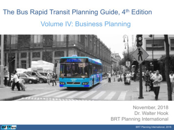
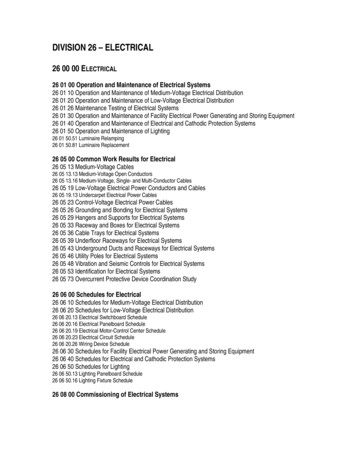
PLANNING and DESIGN GUIDE final.docxSeptember 2014The figure below details in block diagram form the key steps in the design process applied toinfrastructure projects. While it was developed for Utility Infrastructure work, it is no less applicable tomost major projects involving physical structures and systems on campus. It shows the success pathfrom concept to execution of a design. In parallel with this process are other processes such as a QualityProgram containing elements of process improvement (Continuous Improvement) as well as projectmanagement with its focus on cost control and schedule adherence.Design Engineering ProcessThe Ohio State University, FOD – Utilities, UTHVSPage 9 of 186
PLANNING and DESIGN GUIDE final.docxSeptember 20145.1 IntroductionThe Design Process flow chart is a success path. It does not show details such as what happens if, onreview, it is necessary to rework a portion of the design or add to the design. It focuses on the key stepsand the proper sequence of steps, and reviewable products to support a successful project outcome.The following discussion will detail each step and frame its significance to the process as a whole. Onecommon theme that runs from the first to the last step in the process is discipline. It is incumbent on allparticipants in the process to do their homework, come prepared, have thought through their concerns,suggestions and requirements and keep an open mind. Design is a multidiscipline activity with teamworka key element in the process, and with design decisions building on previous design decisions.We need to move forward in the design process with caution. Backtracking is inefficient, and wasteful ofthe resources already committed. Shortcuts and combining steps (taking shortcuts) is extremely risky.For this reason, Value Engineering (VE) is made part of the process from the outset and not applied as adiscrete step later on in the process.One thing that must be stressed as much as discipline, is the need to do adequate preparation, researchand planning. Ten percent of the detail in a project may be contained in the Pre-Schematic andSchematic stages, but 90 percent of the outcome will be determined at this point. Poor planning or anincomplete or faulty definition of project requirements, no matter how well executed in the subsequentproject phases, will still result in a less efficient and less acceptable project outcome.Each step in the process chart is explained below. Sections are number coded respective to the activityblock on the diagram.5.1.1 PreparationThe first step in the design process involves preparation for the design
September 2014 The Ohio State University, FOD - Utilities, UTHVS Page 4 of 186 Planning and Design Guide 1 Introduction 1.1 Campus Planning To be effective, planning for the MV Distribution System needs to be an ongoing process integral with the schematic design of all electrical infrastructure modifications and additions.