Transcription
M710e User Guide and HardwareMaintenance ManualEnergy Star Machine Types: 10UQ, 10UR, 10VB, and 10VC
Note: Before using this information and the product it supports, be sure to read and understand theImportant Product Information Guide and Appendix A “Notices” on page 45.Second Edition (August 2019) Copyright Lenovo 2018, 2019.LIMITED AND RESTRICTED RIGHTS NOTICE: If data or software is delivered pursuant to a General ServicesAdministration “GSA” contract, use, reproduction, or disclosure is subject to restrictions set forth in Contract No. GS35F-05925.
ContentsChapter 1. Overview . . . . . . . . . . . 1Front view . . . . . . . .Rear view . . . . . . . .System board . . . . . .Machine type and model label.1356Chapter 2. Specifications . . . . . . . . 7Chapter 3. Computer locks . . . . . . . 9Locking the computer cover . . . . . . . . . . . 9Attaching a Kensington-style cable lock . . . . . 10Attaching a cable lock . . . . . . . . . . . . 10Chapter 4. Replacing hardware . . . . 11Before replacing hardware . .Knowing FRUs (including CRUs)Locating CRUs and FRUs . . .Replacing the vertical stand . .Replacing the power cord . . .Removing the computer cover .Replacing the front bezel . . . Copyright Lenovo 2018, 2019.11111214151617Replacing the optical drive . . . . . .Replacing the storage drive . . . . . .Replacing the card reader . . . . . . .Replacing the internal speaker . . . . .Replacing the illuminated red dot . . . .Replacing the power supply assembly . .Replacing the cover presence switch . .Replacing the M.2 storage drive . . . .Replacing the coin-cell battery . . . . .Replacing a memory module. . . . . .Replacing a PCI Express card . . . . .Replacing the heat sink and fan assemblyReplacing the microprocessor . . . . .Replacing the system board . . . . . .Completing the parts replacement . . .182023252628293032343537394243Appendix A. Notices . . . . . . . . . . 45Appendix B. Trademarks . . . . . . . 47i
iiM710e User Guide and Hardware Maintenance Manual
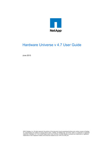
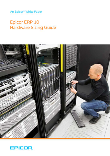
Chapter 1. OverviewThis chapter provides basic information to help you get familiar with your computer.Front viewNote: Your computer model might look slightly different from the illustration.Figure 1. Front view1 Optical drive eject/close button2 Optical drive status indicator3 Internal speaker (optional)4 Storage drive status indicator5 Card reader slot (optional)6 Power indicator7 Power button8 Microphone connector9 Headset connector10 USB 3.1 Gen 1 connectors (2)11 Illuminated red dot1Optical drive eject/close button Copyright Lenovo 2018, 20191
Used to eject the tray of the optical drive. After you insert a disc into the tray, press the eject/close button toclose the tray.2Optical drive status indicatorThis indicator is on when the optical drive is in use.3Internal speaker (optional)Used to listen to the sounds from your computer without using a headset or headphones.4Storage drive status indicatorThis indicator is on when the storage drive is in use.5Card reader slot (optional)Used to read data from a supported memory card.6Power indicatorThis indicator is on when the computer is on.7Power buttonUsed to turn on your computer. When you cannot shut down the computer from the operating system, pressand hold the power button for four or more seconds to turn off the computer.8Microphone connectorUsed to connect a microphone to your computer. You can use the microphone to record sounds or interactwith the computer using speech-recognition software.9Headset connectorUsed to connect headphones to your computer.10USB 3.1 Gen 1 connectorUsed to connect a USB-compatible device. For optimal data transfer, connect a USB 3.1 device to a USB3.1 connector instead of a USB 3.0 or USB 2.0 connector.11Illuminated red dotThis indicator is on when the computer is on.2M710e User Guide and Hardware Maintenance Manual
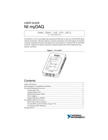
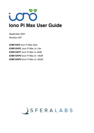
Rear viewNote: Your computer model might look slightly different from the illustration.Figure 2. Rear view1 Audio line-out connector2 DisplayPort -out connector3 VGA-out connector4 USB 2.0 connectors (2)5 USB 3.1 Gen 1 connectors (2)6 Power cord connector7 Serial connector8 Ethernet connector9 Cable lock slots (2)10 Padlock loop11 Security-lock slot12 Serial connector (optional)13 PCI-Express card area1Audio line-out connectorUsed to send audio signals from the computer to external devices, such as powered stereo speakers,headphones, or multimedia keyboards. To connect a stereo system or other external recording device,Chapter 1. Overview3
connect a cable between the audio line-in connector of the device and the audio line-out connector of thecomputer.Note: If your computer has both an audio line-out connector and a headset or headphone connector, alwaysuse the headset connector or headphone connector for earphones, headphones, or a headset. Theheadphone connector does not support headset microphones.2DisplayPort connectorUsed to send audio and video signals from the computer to another audio or video device, such as a highperformance monitor.3VGA-out connectorUsed to send video signals from the computer to another video device, such as a monitor.4USB 2.0 connectorUsed to connect a device that requires a USB 2.0 connection.5USB 3.1 Gen 1 connectorUsed to connect a USB-compatible device. For optimal data transfer, connect a USB 3.1 Gen 1 device to aUSB 3.1 or USB 3.1 Gen 1 connector instead of a USB 2.0 connector.6Power cord connectorUsed to connect the power cord to your computer for power supply.7Serial connectorUsed to connect an external modem, a serial printer, or other devices that use a serial connector.8Ethernet connectorUsed to connect an Ethernet cable for network access.9Cable lock slotsUsed to secure a cable lock.10Padlock loopUsed to secure a padlock.11Security-lock slotUsed to secure a Kensington-style cable lock.12Serial connector (optional)Used to connect an external modem, a serial printer, or other devices that use a serial connector.13PCI-Express card areaTo improve the operating performance of the computer, you can connect PCI-Express cards into this area.Depending on the computer model, the connectors in this area vary.4M710e User Guide and Hardware Maintenance Manual
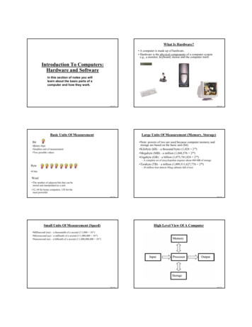
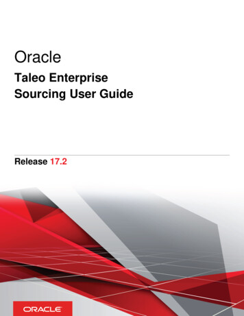
System boardNote: See “Front view” on page 1 and “Rear view” on page 3 for additional component descriptions.Figure 3. System board1 Microprocessor socket2 Microprocessor fan connector3 Memory slot (DIMM1)4 Memory slot (DIMM2)5 Coin-cell battery6 6-pin power connector7 Internal speaker connector8 Illuminated red dot connector9 SATA 3.0 connector10 M.2 storage drive slot11 Parallel connector12 Serial (COM2) connector13 SATA power connector14 SATA 3.0 connector15 Card reader connector16 PCI Express x16 graphics card slot17 Cover presence switch connector (Intrusion switchconnector)18 PCI Express x1 card slotChapter 1. Overview5
Machine type and model labelThe machine type and model label identifies the computer. When you contact Lenovo for help, the machinetype and model information helps support technicians to identify the computer and provide faster service.The machine type and model label is attached on the top of the computer as shown.Figure 4. Machine type and model label6M710e User Guide and Hardware Maintenance Manual
Chapter 2. SpecificationsPower supply 180-watt automatic voltage-sensing power supplyStorage drives 3.5-inch storage drive 2.5-inch storage driveVideo features The integrated graphics card supports the following:– DP-out connector– VGA-out connector The optional discrete graphics card provides an enhanced audio experience and extended capabilities.Audio features The integrated audio card supports the following:– Audio line-out connector– Headset connector– Internal speaker (optional)– Microphone connector The optional discrete audio card provides an enhanced audio experience and extended capabilities.Input/Output (I/O) features Audio connectors (audio line-out, headset, and microphone) Card reader slot (optional) Display connectors (VGA-out) Ethernet connector Serial connectors USB connectorsExpansion Card reader slot Memory slots Optical drive PCI Express x1 card slot PCI Express x16 graphics card slot Storage drive bayNetwork features Ethernet LAN Copyright Lenovo 2018, 20197
Physical dimensions Width: 100.0 mm (3.9 inches) Height: 273.5 mm (10.8 inches) Depth: 303.5 mm (11.9 inches)Weight (without the package)Maximum configuration as shipped: 4.2 kg (11.3 lb)Statement on USB transfer rateDepending on many factors such as the processing capability of the host and peripheral devices, fileattributes, and other factors related to system configuration and operating environments, the actual transferrate using the various USB connectors on this device will vary and will be slower than the data rate listedbelow for each corresponding device.USB deviceData rate (Gbit/s)3.1 Gen 153.1 Gen 2103.2208M710e User Guide and Hardware Maintenance Manual
Chapter 3. Computer locksThis chapter provides instructions on how to lock your computer with the locking devices to keep yourcomputer safe.Locking the computer coverLocking the computer cover helps prevent unauthorized access to the inside of your computer. Yourcomputer features a padlock loop so that the computer cover cannot be removed when a padlock isinstalled.Figure 5. Locking the computer cover Copyright Lenovo 2018, 20199
Attaching a Kensington-style cable lockYou can use a Kensington-style cable lock to secure your computer to a desk, table, or other nonpermanentfixture. The cable lock connects to the security-lock slot at the rear of your computer. Depending on the typeselected, the cable lock can be operated with a key or combination. The cable lock also locks the buttonsused to open the computer cover. This is the same type of lock used with many notebook computers. Youcan order such a cable lock directly from Lenovo by searching for Kensington at:http://www.lenovo.com/supportFigure 6. Attaching a Kensington-style cable lockAttaching a cable lockA cable lock can be used to secure devices, such as the keyboard and the mouse, by locking the devicecables to the computer. The cable lock connects to the cable-lock slots on the rear of the computer. Toinstall a cable lock, do the following:1. Insert the clip 1 into the cable-lock slot 4 .2. Pull the cables you want to lock through the dents in the cable lock.3. Press the clip 2 into the cable-lock slot 3 until it snaps into position.Figure 7. Attaching a cable lock10M710e User Guide and Hardware Maintenance Manual
Chapter 4. Replacing hardwareThis chapter provides instructions on how to replace hardware for your computer.Before replacing hardwareAttention: Do not open your computer or attempt any repairs before reading this section and the ImportantProduct Information Guide.Notes before replacing hardware Use computer components provided only by Lenovo. When installing or replacing an option, use the appropriate instructions explained in this manual along withthe instructions that come with the option. In most areas of the world, Lenovo requires the return of defective CRUs. Information about this will comewith the CRU or will come a few days after the CRU arrives.Handling static-sensitive devicesDo not open the static-protective package containing the new part until the defective part has been removedand you are ready to install the new part. Static electricity, although harmless to you, can seriously damagecomputer components and options.When you handle options and other computer components, take these precautions to avoid static-electricitydamage: Limit your movement. Movement can cause static electricity to build up around you. Always handle options and other computer components carefully. Handle PCI/PCIe cards, memorymodules, system boards, and microprocessors by the edges. Never touch any exposed circuitry. Prevent others from touching the options and other computer components. Touch the static-protective package containing the part to a metal expansion-slot cover or otherunpainted metal surface on the computer for at least two seconds. This reduces static electricity from thepackage and your body before you install or replace a new part. When possible, remove the new part from the static-protective package, and install it directly in thecomputer without setting the part down. When this is not possible, place the static-protective package ona smooth, level surface and place the part on the package. Do not place the part on the computer cover or other metal surface.Knowing FRUs (including CRUs) Field Replaceable Units (FRUs) are computer parts that a trained technician can upgrade or replace. FRUsinclude all CRUs. For detailed FRU information, such as the FRU part numbers and supported computermodels, go to:http://www.lenovo.com/serviceparts-lookup Customer Replaceable Units (CRUs) are computer parts that a user can upgrade or replace.– Self-service CRUs: You can install self-service CRUs easily. These CRUs might be stand-alone,latched, or secured by up to two screws. Examples of self-service CRUs include the keyboard, mouse,any USB device. You are responsible for replacing all self-service CRUs.– Optional-service CRUs: Handling optional-service CRUs requires some technical skills and simple tools(such as a screwdriver). These CRUs are isolated parts within the computer. They are usually Copyright Lenovo 2018, 201911
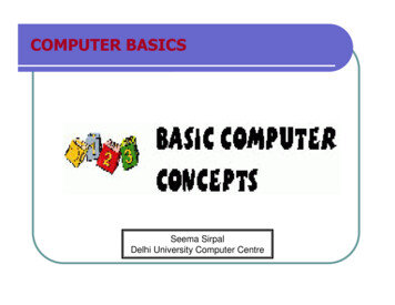
concealed by an access panel that is secured by more than two screws. You must remove the screwsand panel to access the specific CRU. Optional-service CRUs can be removed and installed by usersor, during the warranty period, by a Lenovo service technician.Before replacing FRUsBefore replacing any FRU, read the following: Only certified and trained personnel can service the computer. Before replacing an FRU, read the entire section about replacing the part. Be extremely careful during writing operations such as copying, saving, or formatting.The sequence of the drives in the computer that you are servicing might have been altered. If you selectan incorrect drive, data or programs might be overwritten. Replace an FRU only with another FRU of the correct model.When you replace an FRU, ensure that the model of the machine and the FRU part number are correct. An FRU should not be replaced because of a single, unreproducible failure.Single failures can occur for a variety of reasons that have nothing to do with a hardware defect, such ascosmic radiation, electrostatic discharge, or software errors. Consider replacing an FRU only when aproblem recurs. If you suspect that an FRU is defective, clear the error log and run the test again. If theerror does not recur, do not replace the FRU. Only replace a defective FRU.Locating CRUs and FRUsCustomer Replaceable Units (CRUs) are computer parts that a user can upgrade or replace. There are twotypes of CRUs: self-service and optional-service. Self-service CRUs: You can install self-service CRUs easily. These CRUs might be stand-alone, latched,or secured by up to two screws. Examples of self-service CRUs include the keyboard, mouse, any USBdevice. You are responsible for replacing all self-service CRUs. Optional-service CRUs: Handling optional-service CRUs requires some technical skills and simple tools(such as a screwdriver). These CRUs are isolated parts within the computer. They are usually concealedby an access panel that is secured by more than two screws. You must remove the screws and panel toaccess the specific CRU. Optional-service CRUs can be removed and installed by users or, during thewarranty period, by a Lenovo service technician.Field Replaceable Units (FRUs) are computer parts that a trained technician can upgrade or replace. Fordetailed FRU information, such as the FRU part numbers and supported computer models, go to:http://www.lenovo.com/serviceparts-lookupNotes: 1 , 5 , 6 , 7 , 8 , 9 , 12 , 13 , 16 , 17 , 18 , 19 , 21 and 26 are optional-service CRUs. 4 and 20 are selfservice CRUs. Other parts are Field Replaceable Units. Some of the following components are optional. To replace a component that is not in the list below, contact a Lenovo service technician. For a list ofLenovo Support phone numbers, go to:http://www.lenovo.com/support/phone12M710e User Guide and Hardware Maintenance Manual
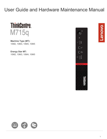
Figure 8. Locating CRUs and FRUs1 Computer cover2 System board3 Microprocessor4 Coin-cell battery5 Memory module6 M.2 storage drive7 Storage drive bracket8 3.5-inch storage drive9 2.5-inch storage drive10 Storage drive cable11 Optical drive cable12 Optical drive bracket13 Optical drive14 Card readerChapter 4. Replacing hardware13
15 Internal speaker16 Front bezel17 Keyboard18 Mouse19 Power cord20 Power supply assembly21 PCI Express card22 Chassis23 Cover presence switch24 Heat sink and fan assembly25 Fan duct26 Vertical standReplacing the vertical standAttention: Do not open your computer or attempt any repairs before reading the Important ProductInformation Guide.1. Remove any media from the drives and turn off all connected devices and the computer.2. Disconnect all power cords from electrical outlets and disconnect all cables from the computer.3. Replace the vertical stand.Figure 9. Removing the vertical stand14M710e User Guide and Hardware Maintenance Manual
Figure 10. Installing the vertical stand4. Complete the replacement. See “Completing the parts replacement” on page 43.Replacing the power cordAttention: Do not open your computer or attempt any repairs before reading the Important ProductInformation Guide.1. Remove any media from the drives and turn off all connected devices and the computer.2. Disconnect all power cords from electrical outlets and disconnect all cables from the computer.3. Replace the power cord.Chapter 4. Replacing hardware15
Figure 11. Removing the power cordFigure 12. Installing the power cordRemoving the computer coverAttention: Do not open your computer or attempt any repairs before reading the Important ProductInformation Guide.CAUTION:Before you open the computer cover, turn off the computer and wait several minutes until thecomputer is cool.1. Remove any media from the drives and turn off all connected devices and the computer.2. Disconnect all power cords from electrical outlets and disconnect all cables from the computer.16M710e User Guide and Hardware Maintenance Manual
3. Unlock any locking device that secures the computer cover.4. Remove the computer cover.Figure 13. Removing the computer cover5. Complete the replacement. See “Completing the parts replacement” on page 43.Replacing the front bezelAttention: Do not open your computer or attempt any repairs before reading the Important ProductInformation Guide.1. Remove the computer cover. See “Removing the computer cover” on page 16.2. Replace the front bezel.Chapter 4. Replacing hardware17
Figure 14. Removing the front bezelFigure 15. Installing the front bezel3. Complete the replacement. See “Completing the parts replacement” on page 43.Replacing the optical driveAttention: Do not open your computer or attempt any repairs before reading the Important ProductInformation Guide.1. Remove the computer cover. See “Removing the computer cover” on page 16.2. Remove the front bezel. See “Replacing the front bezel” on page 17.18M710e User Guide and Hardware Maintenance Manual
3. Disconnect the signal cable and the power cable from the optical drive.4. Replace the optical drive.Figure 16. Removing the optical driveFigure 17. Removing the optical drive bracketChapter 4. Replacing hardware19
Figure 18. Installing the optical drive bracketFigure 19. Installing the optical drive5. Connect the signal cable and the power cable to the new optical drive.6. Reinstall the removed parts. To complete the replacement, see “Completing the parts replacement” onpage 43.Replacing the storage driveAttention: Do not open your computer or attempt any repairs before reading the Important ProductInformation Guide.1. Remove the computer cover. See “Removing the computer cover” on page 16.2. Remove the front bezel. See “Replacing the front bezel” on page 17.3. Remove the optical drive. See “Replacing the optical drive” on page 18.4. Disconnect the signal cable and the power cable from the storage drive.20M710e User Guide and Hardware Maintenance Manual
5. Remove the storage drive bracket.Figure 20. Removing the storage drive bracket6. Replace the storage drive. 3.5-inch storage driveFigure 21. Removing the 3.5-inch storage driveChapter 4. Replacing hardware21
Figure 22. Installing the 3.5-inch storage drive 2.5-inch storage driveFigure 23. Removing the 2.5-inch storage drive22M710e User Guide and Hardware Maintenance Manual
Figure 24. Installing the 2.5-inch storage drive7. Install the storage drive bracket.Figure 25. Installing the storage drive bracket8. Connect the signal cable and the power cable to the new storage drive.9. Reinstall the removed parts. To complete the replacement, see “Completing the parts replacement” onpage 43.Replacing the card readerAttention: Do not open your computer or attempt any repairs before reading the Important ProductInformation Guide.1. Remove the computer cover. See “Removing the computer cover” on page 16.2. Remove the front bezel. See “Replacing the front bezel” on page 17.3. Remove the optical drive. See “Replacing the optical drive” on page 18.4. Remove the storage drive bracket. See “Replacing the storage drive” on page 20.5. Disconnect the card reader cable from the system board.6. Replace the card reader.Chapter 4. Replacing hardware23
Figure 26. Removing the card reader bracketFigure 27. Removing the card readerFigure 28. Installing the card reader24M710e User Guide and Hardware Maintenance Manual
Figure 29. Installing the card reader bracket7. Connect the new card reader cable to the system board.8. Reinstall the removed parts. To complete the replacement, see “Completing the parts replacement” onpage 43.Replacing the internal speakerAttention: Do not open your computer or attempt any repairs before reading the Important ProductInformation Guide.1. Remove the computer cover. See “Removing the computer cover” on page 16.2. Remove the front bezel. See “Replacing the front bezel” on page 17.3. Remove the optical drive. See “Replacing the optical drive” on page 18.4. Remove the storage drive bracket. See “Replacing the storage drive” on page 20.5. Disconnect the internal speaker cable from the system board.6. Replace the internal speaker.Figure 30. Removing the internal speakerChapter 4. Replacing hardware25
Figure 31. Installing the internal speaker7. Connect the new internal speaker cable to the system board.8. Reinstall the removed parts. To complete the replacement, see “Completing the parts replacement” onpage 43.Replacing the illuminated red dotAttention: Do not open your computer or attempt any repairs before reading the Important ProductInformation Guide.1. Remove the computer cover. See “Removing the computer cover” on page 16.2. Remove the front bezel. See “Replacing the front bezel” on page 17.3. Remove the optical drive. See “Replacing the optical drive” on page 18.4. Remove the storage drive bracket. See “Replacing the storage drive” on page 20.5. Disconnect the illuminated red dot cable from the system board.6. Replace the illuminated red dot.Figure 32. Removing the illuminated red dot cover26M710e User Guide and Hardware Maintenance Manual
Figure 33. Removing the illuminated red dotFigure 34. Installing the illuminated red dotFigure 35. Installing the illuminated red dot cover7. Connect the new illuminated red dot cable to the system board.8. Reinstall the removed parts. To complete the replacement, see “Completing the parts replacement” onpage 43.Chapter 4. Replacing hardware27
Replacing the power supply assemblyAttention: Do not open your computer or attempt any repairs before reading the Important ProductInformation Guide.Although there are no moving parts in your computer after the power cord has been disconnected, thefollowing warnings are required for your safety and proper Underwriters Laboratories (UL) certification.CAUTION:Never remove the cover on a power supply or any part that has the following label attached.Hazardous voltage, current, and energy levels are present inside any component that has this labelattached. There are no serviceable parts inside these components. If you suspect a problem with oneof these parts, contact a service technician.1. Remove the computer cover. See “Removing the computer cover” on page 16.2. Remove the front bezel. See “Replacing the front bezel” on page 17.3. Remove the optical drive. See “Replacing the optical drive” on page 18.4. Remove the storage drive bracket. See “Replacing the storage drive” on page 20.5. Disconnect the power supply assembly cable from the system board.6. Replace the power supply assembly.Figure 36. Removing the power supply assembly28M710e User Guide and Hardware Maintenance Manual
Figure 37. Installing the power supply assembly7. Connect the new power supply assembly cable to the system board.8. Reinstall the removed parts. To complete the replacement, see “Completing the parts replacement” onpage 43.Replacing the cover presence switchAttention: Do not open your computer or attempt any repairs before reading the Important ProductInformation Guide.1. Remove the computer cover. See “Removing the computer cover” on page 16.2. Remove a PCI Express card. See “Replacing a PCI Express card” on page 35.3. Disconnect the cover presence switch cable from the system board.4. Replace the cover presence switch.Figure 38. Removing the cover presence switchChapter 4. Replacing hardware29
Figure 39. Installing the cover presence switch5. Connect the new cover presence switch cable to the system board.6. Reinstall the removed parts. To complete the replacement, see “Completing the parts replacement” onpage 43.Replacing the M.2 storage driveAttention: Do not open your computer or attempt any repairs before reading the Important ProductInformation Guide.1. Remove the computer cover. See “Removing the computer cover” on page 16.2. Remove the front bezel. See “Replacing the front bezel” on page 17.3. Remove the optical drive. See “Replacing the optical drive” on page 18.4. Remove the storage drive bracket. See “Replacing the storage drive” on page 20.5. Replace the M.2 storage drive.Figure 40. Removing the screw30M710e User Guide and Hardware Maintenance Manual
Figure 41. Removing the M.2 storage driveFigure 42. Installing the M.2 storage driveFigure 43. Installing the M.2 screw6. Reinstall the removed parts. To complete the replacement, see “Completing the parts replacement” onpage 43.Chapter 4. Replacing hardware31
Replacing the coin-cell batteryAttention: Do not open your computer or attempt any repairs before reading the Important ProductInformation Guide.Your computer has a special type of memory that maintains the date, time, and settings for built-in features,such as parallel connector assignments (configurations). A coin-cell battery keeps this information activewhen you turn off the computer.The coin-cell battery normally requires no charging or maintenance throughout its life; however, no coin-cellbattery lasts forever. If the coin-cell battery fails, the date, time, and configuration information (includingpasswords) are lost. An error message is displayed when you turn on the computer.To replace the coin-cell battery,1. Remove the computer cover. See “Removing the computer cover” on page 16.2. Remove the front bezel. See “Replacing the front bezel” on page 17.3. Remove the optical drive. See “Replacing the optical drive” on page 18.4. Remove the storage drive bracket. See “Replacing the storage drive” on page 20.5. Replace the coin-cell battery.Figure 44. Removing the coin-cell battery32M710e User Guide and Hardware Maintenance Manual
Figure 45. Removing the coin-cell batteryFigure 46. Installing the coin-cell batteryChapter 4. Replacing hardware33
Figure 47. Installing the coin-cell battery6. Reinstall the removed parts. To complete the replacement, see “Completing the parts replacement” onpage 43.To dispose of the coin-cell battery, refer to Lithium coin-cell battery notice in theSafety and Warranty Guide.Replacing a memory moduleAttention: Do not open your computer or attempt any repairs before reading the Important ProductInformation Guide.If your computer supports one memory module, install the module into the DIMM 1 slot. If your computersupports two memory modules, install one memory module into the DIMM 1 slot first and then install theother into the DIMM 2 slot.1. Remove the computer cover. See “Removing the computer cover” on page 16.2. Remove the front bezel. See “Replacing the front bezel” on page 17.3. Remove the optical drive. See “Replacing the optical drive” on page 18.4. Remove the storage drive bracket. See “Replacing the storage drive” on page 20.5. Replace a memory module.34M710e User Guide and Hardware Maintenance Manual
Figure 48. Removing a memory moduleFigure 49. Installing a memory module6. Reinstall the removed parts. To complete the replacement, see “Completing the parts replacement” onpage 43.Replacing a PCI Express cardAttention: Do not open your computer or attempt any repairs before reading the Important ProductInformation Guide.1. Remove the computer cover. See “Removing the computer cover” on page 16.2. Replace a PCI Express card.Chapter 4. Replacing hardware35
Figure 50. Removing a PCI Express cardNote: If the card is held in place by a retaining latch, press the latch 1 as shown to disengage the latch.Then, gently remove the card from the slot.Figure 51. Installing a PCI Express card36M710e User Guide and Hardware Maint
Rear view Note: Your computer model might look slightly different from the illustration. Figure 2. Rear view 1 Audio line-out connector2 DisplayPort -out 3 VGA-out connector 4 USB 2.0 connectors (2) 5 USB 3.1 Gen 1 connectors (2) 6 Power cord connector 7 Serial connector 8 Ethernet connector 9 Cable lock sl