Transcription
HindawiWireless Communications and Mobile ComputingVolume 2020, Article ID 8857271, 9 pageshttps://doi.org/10.1155/2020/8857271Research ArticleImage Dehazing Method of Transmission Line for UnmannedAerial Vehicle Inspection Based on Densely ConnectionPyramid NetworkJun Liu,1,2 Rong Jia,1 Wei Li,1 Fuqi Ma ,3 and Xiaoyang Wang41Xi’an University of Technology, 710048 Shaanxi Province, ChinaState Grid Shaanxi Maintenance Company, 710065 Shaanxi Province, China3School of Electrical Engineering and Automation, Wuhan University, Wuhan, China4Guangzhou Power Supply Company, 210000 Guangzhou, Wuhan, China2Correspondence should be addressed to Fuqi Ma; 18392647176@163.comReceived 14 July 2020; Revised 26 August 2020; Accepted 21 September 2020; Published 8 October 2020Academic Editor: Panagiotis SarigiannidisCopyright 2020 Jun Liu et al. This is an open access article distributed under the Creative Commons Attribution License, whichpermits unrestricted use, distribution, and reproduction in any medium, provided the original work is properly cited.The quality of the camera image directly determines the accuracy of the defect identification of the transmission line equipment.However, complex external factors such as haze can seriously affect the image quality of the aircraft. The traditional imagedehazing methods are difficult to meet the needs of enhanced image inspection in complex environments. In this paper, theimage enhancement technology in haze environment is studied, and an image dehazing method of transmission line based ondensely connection pyramid network is proposed. The method uses an improved pyramid network for transmittance mapcalculation and uses an improved U-net network for atmospheric light value calculation. Then, the transmittance map,atmospheric light value, and dehazed image are jointly optimized to obtain image dehazing model. The method proposed in thispaper can improve image brightness and contrast, increase image detail information, and can generate more realistic deblurimages than traditional methods.1. IntroductionIn recent years, with the breakthrough of key transmissiontechnologies such as intelligent autonomous operations andmaintenance systems, UAV inspection [1–7] has been rapidly promoted and applied. For the patrol pictures, videosand other data generated during the patrol operation of thetransmission line UAV, pattern recognition and computervision technology [8–12] can be used to complete the discrimination work with the help of computers. This technology uses the deep learning network [13–18] to train andlearn the fault samples of transmission line equipment, toobtain amature power vision target detection model, andautomatically realize the target detection and fault locationof the machine patrol image. The recognition accuracy andpositioning accuracy of the target detection algorithm arepositively correlated with the quality of the machine patrolimage. The higher the image quality, the more effective thedetection algorithm. However, drone inspections are mostlycarried out in the wild, and their complex weather conditionsplay a crucial role in the quality of the photos taken. Due toenvironmental pollution, in recent years, a large range ofhaze weather has occurred in China, and the visibility ofthe field of vision has declined sharply.Particulate matter in the atmosphere will seriously scatterthe light coming into the camera, causing the brightness andcontrast of transmission line pictures taken during dronepatrols to decrease. The background image information isblurred, which ultimately leads to a serious degradation ofimage quality and the accuracy of image target detection.Therefore, it is urgent to study the image enhancement technology which is more suitable for the smog environment.Image dehazing has always been a hot issue in the field ofimage enhancement. The research on image dehazingmethod at home and abroad is mainly divided into two categories: nonphysical methods based on image enhancement
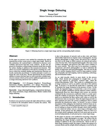
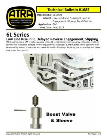
2and restoration methods based on imaging models [19–23].The method of image enhancement is mainly to use the traditional image enhancement technology to directly filter thelow-quality foggy image to remove the influence of noise inthe image and restore the image clarity. The typical imagedehazing method based on image enhancement includes histogram equalization [24–28], wavelet transform method, andRetinex algorithm [29–31]. The method based on imagephysical repair is mainly to study the degradation model offoggy image and inversely solve the optical imaging modelto obtain the dehazing image. This method can retain thedetailed information of the image and improve the authenticity of the image. It is the mainstream direction of the currentresearch on dehazing algorithms, and its representativemethod is based on the partial differential equation dehazingmethod [32], defog method based on depth of field [33, 34],defog method based on a priori theory, and defog methodbased on deep learning [35–37]. In recent years, CNN networks have achieved great success in the fields of image segmentation, target detection, object classification, etc. Affectedby this, more and more scholars have begun to introduceCNN networks into image dehazing algorithms. Literature[38–41] obtained the transmittance map of foggy images byestablishing a shallow neural network and then used theimage degradation model to achieve image dehazing. Literature [42, 43] combines convolutional neural networks andguided filters to achieve the restoration of foggy images.Image dehazing method based on convolutional neural network achieves good dehazing results in some specific scenarios, but the network depth is insufficient, and the networkarchitecture has defects that lead to unsatisfactory effects onscenes with high fog density.Through the study of the existing image dehazingmethod, it is found that the traditional image dehazingmethod relies heavily on prior knowledge [44]. The modelis seriously simplified, and the detail information of thedehazing image is insufficiently restored. The imageenhancement method does not consider the physical imagingmodel, but only improves the visual effect of the image bychanging the contrast and gray value of the image; image restoration is based on the imaging physical model, using darkchannel prior theory [45] to repair the haze image. Compared with image enhancement, this method has betterdehazing effect, but there are some simplifications to theimage generation model during the implementation process,and there is still a certain difference between the restoredimage and the real image. In view of the shortcomings ofthe traditional image dehazing method, this paper proposesthe image dehazing method of transmission line machinepatrol image based on densely connected pyramid network.It directly embeds the atmospheric degradation model intothe deep learning framework and uses physical principles torestore the image fog. The fog image obtained by this methodis closer to the real image in visual effect.2. Single Image Defog Model2.1. Haze Image Optical Attenuation Model. In the field ofimage processing, the model [46] shown in Equation (1) isWireless Communications and Mobile Computingoften used to describe the image formation process in fogand haze.I ðz Þ J ðz Þt ðz Þ Að1 t ðz ÞÞ:ð1ÞAmong them, I represents the real image taken by thecamera in the case of fog and haze; J represents the clear picture taken in the case of clear weather. A is the ambient lightintensity, which is usually assumed to be constant in the localarea of the image; t is the transmittance, which is used todescribe the proportion of light that enters the camera lensthrough the haze; z represents the position of the pixel inthe image. Transmittance is a factor related to distance,which represents the proportion of light transmitted by thetarget object through the atmosphere and reaching the camera lens. When the atmospheric light value A in the local areaof the image is constant, the transmittance can usually beexpressed as Equation (2).t ðz Þ e βdðzÞ :ð2ÞIt can be seen from Equation (1) that the image taken infog and haze is the superposition of the light passing throughthe fog and the atmospheric light scattered by the fog andhaze in a clear background image. The process of imagedehazing is to find the global atmospheric light value A andtransmittance t from the foggy image I, inversely calculateEquation (1), and finally obtain the clear image J.2.2. Model Architecture of Densely Connected PyramidDehazing Network. This paper proposes a new deeplearning-based transmission line machine patrol imagedehazing network, called dense connection pyramid dehazing network (DCPDN). The network uses the method ofend-to-end learning to achieve the purpose of image dehazing. The essence of the DCPDN network is to use the physicalmethod of image restoration to solve the problem of imagedegradation. The end-to-end image dehazing repair isachieved by embedding the atmospheric degradation modelEquation (1) into the deep learning network. In the dehazingnetwork, the deep fusion between the transmittance mapestimation module, the atmospheric light value estimationmodule, and the dehazing image is realized, and the information exchange and restriction between the various modulesare achieved to achieve the purpose of commonoptimization.The architecture of the DCPDN network proposed in thispaper is shown in Figure 1. The network is composed of fourparts: (1) a transmission diagram estimation module withdensely connected pyramids, (2) atmospheric light value estimation module, (3) dehazing module based on image degradation equation, and (4) joint discriminator module. Thefour modules are introduced in detail below:2.2.1. Pyramid Densely Connected Transmission GraphEstimation Network. Inspired by the previous method usingmultilevel features to estimate the transmittance map [47–51], this paper also attempts to use the multilevel featuresof the image to estimate the transmittance map, as shown
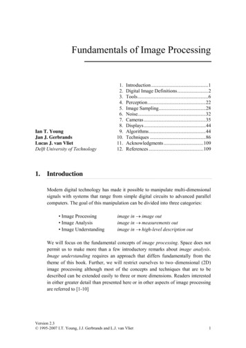
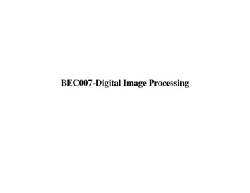
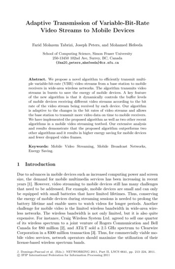
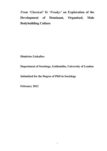
Wireless Communications and Mobile Computing3Transmittance chartPyramid dense connection encoder–decoderJoint discriminatorSpliceInputTransmittance plotestimationt (z)Atmospheric light mapI(z)–A(z)(1–t(z)J(z) t(z)DefogimageJ(z)Atmospheric light value estimationA (z)Figure 1: Densely connected pyramid dehazing network.in Figure 2. A densely connected encoding-decoding structure is proposed. The encoder-decoder uses dense blocks asthe basic structural unit, and dense connections are madebetween layers within the dense blocks. Dense blocks cannot only use CNN network to extract multilevel features ofthe image, but also ensure better convergence of the entireencoding-decoding network. In addition, the encoderdecoder also uses a multilayer pyramid pooling module,which uses the global transmission information of the imageto estimate the transmittance map, avoiding the problem thatthe network pays too much attention to local details andignores the global information.In the encoder, it is a first traditional convolution blockand then four dense blocks. The output of the encoder is1/32 of the original input image. Corresponding to theencoder is the decoder, whose structure is completely symmetrical with the encoder and contains four dense blocksand one convolution block. The output of the decoder andthe original image have the same size, and the correspondingmodules of the two are directly connected. Although theproposed densely connected encoding-decoding structurecombines different features within the network, the transmittance graph output only through the encoder-decoder stilllacks global structural information with different scale features. This is because the features extracted from the imagesof different scales are not directly used to generate the featurerate map, so after the codec, the network has added a multilevel pyramid pooling module to use the feature informationobtained by each layer of the feature pyramid. The finaltransmittance map is estimated. The pyramid pooling module designed in this paper contains four levels of poolingoperations, and the output size is 1/4, 1/8, 1/16, and 1/32 ofthe original image size. Then, all the four sizes of transmittance maps are upsampled to the original image size, andthe original images are connected, respectively, and finally,the fined transmittance map is obtained.2.2.2. Atmospheric Light Value Estimation Network. The calculation of atmospheric light values in the traditional imagedehazing method is based on empirical formulas. The atmospheric light map used for dehazing is also rough and notprecise, so it is difficult to obtain satisfactory dehazingimages. This network proposes an improved U-net networkwhen solving atmospheric light values, as shown inFigure 3. The entire network includes two parts: upsamplingand downsampling. The upsampling process is to capture thecontext information of the image, and the downsamplingprocess is to obtain the local precise information of theimage. In the downsampling process, every two 3 3 convolutional layers will be followed by a 2 2 pooling layer. ReLUis used as the activation function after each convolutionallayer. The upsampling process is symmetrical with the downsampling process. Each 2 2 pooling layer is followed by two3 3 convolutional layers. The high-pixel atmospheric lightfeature maps extracted during the downsampling processare directly transmitted to the corresponding upsamplingprocess to guide the generation of new feature maps andretain some of the important feature information obtainedduring the previous downsampling process to the greatestextent. The final output of the network is a refined atmospheric light map. The value of each pixel in the picture isas close as possible to the atmospheric light value in the caseof real haze.2.2.3. Dehazing Module Based on Image DegradationEquation. In order to realize image dehazing using physicalimaging principles, this network directly embeds the imagedegradation model into the dehaze network. As shown inthe dehazing module in Figure 1, accurate transmittancemap and atmospheric light map can be obtained from thefirst two modules, and the dehazing image can be easilyobtained by using the image degradation model.2.2.4. Joint Optimization Discriminant Network. In order toestablish the relationship between transmittance map, atmospheric light map, and dehazing image, this paper builds ajoint optimization discriminant network based on GANnetwork [51]. The discrimination network uses the high
4Wireless Communications and Mobile Computing1/41/8Up1/161/32Figure 2: Densely connected encoding-decoding structure.OutputInputMax poolConv 3 3 ReLUCopy and cropMax pool 2 2Up–Conv 2 2Conv 1 1Figure 3: Atmospheric light value estimation network.correlation between the three to optimize the generatedtransmittance map, atmospheric light map, and dehazingimage and finally obtain a clear and true dehazing image.LetGt and Gd denote the generation networks of clear imagesand transmittance maps respectively. As shown in Equation(3), the first part and the second part of the formula are thegames between the generator and the discriminator. Continuously optimize the generation and discrimination networkand finally be able to generate the transmittance map anddehazing image as realistic as possible. The third part of theformula is to compare the actual clear image with thedefogged image to further optimize the dehazing image. min max EI pdataðIÞ log 1 Djoint ðGt ðI ÞÞGt ,Gd Djoint EI pdataðIÞ log 1 Djoint ðGd ðI ÞÞ Et, J pdataðt,J Þ log Djoint ðGt ðt, J ÞÞ :2.3. Defog Network Loss Functionð3Þ2.3.1. Edge Protection Loss Function. For the training of deeplearning networks, the simplest loss function is the L2 lossfunction, but after many experiments, it is found that onlythe L2 loss function is used for network training, and the output image is often blurred. Through in-depth analysis of theimage, it is found that the value of the edge pixel point of thetarget object has a discontinuity. It can be characterized bycalculating the gradient of the pixel value. The edge and contour features of the target object can be captured in the firstfew layers of the CNN structure, so the first few layers ofthe convolutional neural network can be used as the edgedetector for target feature extraction. So the first few layersof the convolutional neural network can be used as the edgedetector for target feature extraction. Based on the aboveanalysis, this paper proposes an edge protection loss function, which adds a two-way gradient loss and feature edgeloss on the basis of the L2 loss function. The function expression is shown in Equation (4).LE λE,l2 LE,l2 λE,g LE,g λE, f LE, f :ð4Þ
Wireless Communications and Mobile Computing5(a) Foggy image(b) Proposed method to defog images(c) Foggy image(d) Proposed method to defog imagesFigure 4: Image dehazing result graph.LE is the retention losses for the entire edge of the targetobject, LE,l2 is the loss for L2, LE,g is for the horizontal andvertical gradient loss, andLE, f is a characteristic loss. Thespecific calculation formula of loss is shown in Equation (5).LE,g ðH x ðGt ðI ÞÞÞw,h ðH x ðt ÞÞw,hw ,h H y ðGt ðI ÞÞ w,h H y ðt Þ2 w ,h 2ð5Þ:c1 ,w1 ,h1ðV 1 ðGt ðI ÞÞÞc1 ,w1 ,h1 ðV 1 ðt ÞÞc1 ,w1 ,h1 c2 ,w2 ,h22ðV 2 ðGt ðI ÞÞÞc2 ,w2 ,h2 ðV 2 ðt ÞÞc2 ,w2 ,h22:ð6ÞV i is on behalf of the CNN structure, ci , wi , hi , V i are thedimension of the corresponding low-level feature.λE,l2 , λE,g ,andλE, f are the weight of the balance loss function.2.3.2. Overall Loss Function. For the entire network training,in addition to the edge protection loss function, the loss function of the atmospheric light map, the loss function of thedehazing module, and the loss function of the joint optimization discriminator are also required. The overall loss functioncan be expressed as Equation (7).L Lt La Ld λ j L j :L j log Djoint ðGt ðI ÞÞ log Djoint ðGd ðI ÞÞ,ð8Þwhere j is a constant.3. Model TrainingH x and H y calculate the image pixel gradient along thehorizontal and vertical, respectively, and w h representsthe width and height of the output feature map. Feature lossdefinition is shown in Equation (6).LE , f composed of the traditional L2 loss Ld , which denotes defogloss, which also consists of L2 loss only.L j is for the jointdiscriminator loss, andL j is defined as Equation (8).ð7ÞLt consists of edge retention loss LE x, and La is the lossfunction of the atmospheric light calculation module that is3.1. Composition of the Dataset. In order to train the denseconnection pyramid dehazing network (DCPDN), this paperconstructs a training set containing 8000 images throughsimulation. The training set contains a total of four datatypes, namely, foggy images, clear images, transmittancemaps, and atmospheric light maps. In the process of obtaining the training set through simulation, we randomly sampleas the atmospheric light value in the range of 0.5–1, And construct of the corresponding atmospheric light map, we randomly select the data as the scattering coefficient in therange of 0.4–1.6 and generate the corresponding transmittance map. We randomly selected 2000 transmission lineimages captured by drone patrol under clear weather andsynthesized them according to the foggy image model Equation (1), obtaining a total of 8000 simulation images. Then,the dataset is divided into training set, validation set, and testset according to 7 : 2 : 1. In order to ensure that the traineddehazing network has good generalization performance, thetraining set in this paper does not contain any pictures inthe verification test set.3.2. Training Details of the Dehazing Network. In the modeltraining process, we choose λE,l2 1, λE,g 0:5, and λE, f 0:8 in the transmission graph as parameters of the loss function, λ j 0:25. As a parameter of the loss function, the jointoptimization discriminator is optimized. The entire network
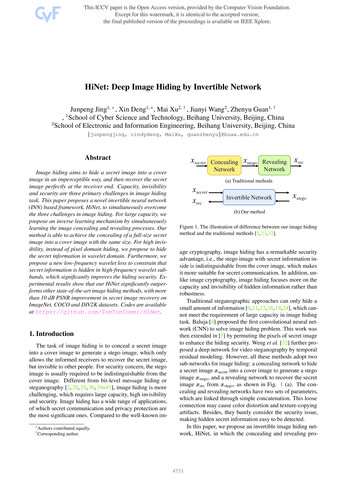
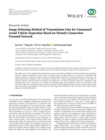
6Wireless Communications and Mobile Computing(a) Foggy image(b) He method to defog images(c) Li method to defog images(d) Proposed method to defog imagesFigure 5: Contrast of image dehazing result.Table 1: PSNR and SSIM of dehazing image.MethodHe image dehazing methodLi image dehazing methodDCPDN image dehazing 478uses Gaussian random variables to initialize the weight parameters, and the Adam optimization algorithm is used to optimize the network. The initial learning rate of the generatorand the joint discriminator is set to 2 10 3 . The learning rateis a key parameter that affects the model training.The smaller the learning rate, the less likely to miss thelocal minimum, but the smaller the learning rate, the slowerthe model convergence. The number of samples in the training set of this network is not very large, so the full training setis selected for the batch size. Each iteration of the networkcan make full use of the feature information of the data inthe entire training set and can accelerate the network’sapproach to the extreme point. In addition, the size of theimage input from the network is uniformly adjusted to 512 512. In the end, the paper performed 40,000 iterations onthe network and determined all the parameters of the network through cross-validation.During the initial training of the model, we found thatstarting to train the entire network directly, the convergencespeed of the network is very slow. The possible reason is thatthe gradient descent direction of different modules in the network in the initial training period is inconsistent, causing theconvergence speed of the entire network to decrease. In orderto solve this problem and accelerate training, this methodintroduces a staged learning strategy, which has been usedin multimodel recognition [52] and feature learning [53]The algorithm is applied. We input the information in thetraining data to different modules in the network, and eachmodule is trained separately without affecting each other,and we update the parameters independently. After eachmodule completes the “initialization” of parameters, we associate different modules with each other to jointly optimizethe entire network.4. Analysis of Experimental Results4.1. Defog Image Rendering Comparison. We randomly selecta foggy image from the UAV inspection image sample libraryand use the DCPDN dehazing algorithm for dehazing. Theresults are shown in Figure 4.Figures 4(a) and 4(c) are the original foggy images.Figures 4(b) and 4(d) are the images after DCPDN method.It can be seen from Figure 4 that the method in this papercan effectively remove the haze in the image and restore theimage detail information.We randomly select a foggy image from the UAV inspection image sample library and use the He dehazing algorithm[37], Li dehazing algorithm [38], and DCPDN dehazing algorithm for dehazing. The results are shown in Figure 5.Figures 5(a)–5(d) are the original foggy image, the imageafter He dehazing method, the image after Li dehazingmethod, and the image after DCPDN method, respectively.It can be seen from Figure 5(b) that the image processed bythe He image dehazing method is seriously distorted in thesky area, and it is not good for dehazing images containinglarge white areas. It can be clearly seen from Figure 5(c) thatthe image dehazing is not thorough enough. The main reasonis that the CN method used in the Li method has fewer layers,and the fog feature extraction is insufficient, resulting in thepresence of fog in the processed image. Figure 5(d) is theresult obtained by adopting the new dehazing network
Wireless Communications and Mobile Computing7Table 2: Target detection results.Foggy imageHe defog imageLi defog imageThis article methodTower failure (AP)Small-size fittings (AP)Ground wire fault (AP)Insulator failure 0130.53040.58590.58800.6770proposed in this paper. From the visual effect, it is obviouslysuperior to the first two methods, and the image detail information is restored while ensuring the image brightness andcontrast.4.2. Comparison of Dehazing Image Indicators. Peak signalto-noise ratio (PSNR) and structural similarity (SSIM) areoften used as the basis for image quality evaluation. The peaksignal-to-noise ratio is defined by the ratio of the maximumsignal power to the signal noise power, usually expressed indecibels. Structural similarity is to evaluate the image qualityfrom the image brightness, contrast, and structural properties of the target object. We calculate the PSNR and SSIMvalues of Figure 5, and the results are shown in Table 1.It can be seen from the comparison of the PSNR value andSSIM value in Table 1 that the DCPDN image dehazingmethod proposed in this paper is better than the image dehazing method of He and Li, and the PSNR value and SSIM valueare higher. It shows that the image dehazing method proposedin this paper is good for image repair and can generate dehazing images with high similarity to clear images.4.3. Target Detection Accuracy Comparison. In the field oftarget detection, two indicators, average precision (AP) andmean average precision (mAP), are usually used to evaluatethe pros and cons of the target detection algorithm. The average accuracy is used to measure the recognition accuracy of atarget detection algorithm for an object. The mean averageaccuracy is used to measure the recognition accuracy of analgorithm on all targets. Generally speaking, mAP is a simpleaverage of multitarget detection AP.From the test set, 100 randomly selected images offoggy transmission lines with pole tower failure, smallsize fitting failure, ground conductor failure, and insulatorfailure were selected. The He image dehazing method, Liimage dehazing method, and DCPDN image dehazingmethod were used for image dehazing, respectively. TheFaster Rcnn target detection algorithm [54] was used todetect the equipment defect targets for foggy images, Hedehazing images, Li dehazing images, and DCPDN dehazing images. We calculate the AP values of the four faultsand the mAP values of each group of images separately.The results are shown in Table 2.It can be seen from the results in Table 2 that the APvalue and mAP value of the target detection algorithm afterimage dehazing have been improved, and the effect of themethod proposed in this article is the most obvious, indicating that the preprocessing of image dehazing can improve theaccuracy of target detection. The AP value of the target detection algorithm for tower failure, ground conductor failure,and insulator failure has been greatly improved. The APvalue of small-size metal fittings has a small increase, whichproves that the image dehazing process can improve theoverall image quality, and the effect of recovering the edgeinformation of large-size target objects is obvious.5. ConclusionThis paper proposes an image dehazing method of transmission line machine patrol image based on densely connectedpyramid network. It embeds the atmospheric degradationmodel directly into the deep learning framework and usesphysical principles to restore the image. For the calculationof the transmittance graph, this paper proposes a new denseconnection encoding-decoding structure with multilevelpooling modules and redesigns the edge retention loss function. This method introduces a joint discriminant optimizerbased on GAN network in the network, which can jointlyoptimize the transmittance map and dehazing image withhigh correlation. Then use the sample set designed in thispaper to train the network to obtain an image dehazingmodel suitable for the transmission line background. Experiments show that the dehazing image obtained by the methodproposed in this paper is closer to the real image in visualeffect. Using the dehazing algorithm proposed in this paperfor image enhancement can improve the accuracy of the target detection algorithm.Although the proposed method indeed promotes thequality of transmission line UAV inspection image, it is stillnot a real-time solution. Considering the actual problem thatfor the deep learning model proposed in this paper, the number of existing samples is still insufficient and future work canfurther increase the number of training set samples throughdata expansion method. In addition, the main work carriedout in this paper is to enhance the image containing haze,but there are still some problems in the actual aircraft patrolimage including raindrop image and motion blur. Thus,there is an important and meaningful need for work in thefuture to explore more comprehensive image enhancementmethod for unmanned aerial vehicle inspection in :SSIM:AP:Convolutional neural networkUnmanned aerial vehicleDensely connection pyramid networkPeak signal-to-noise ratioStructural similarityAverage precision.
8Data AvailabilityThe authors do not share the data, due to the requirements ofthe foundations.Conflicts of InterestThe authors declare that they have no competing interests.AcknowledgmentsThe authors would like to thank the anonymous reviewersfor their helpful insights and suggestions which have substantially improved the content and presentation of thispaper. This work was supported by the National Natural Science Foundation of China (No. 51777142, No. 71371127, No.91846301, No. 71790615, No. 51779206, and No. 71431006),the Key Project for Philosophy and Social Sciences Researchof Shenzhen City (No. 135A004), Key Project of Natural Science Basic Research Plan in Shaanxi Province of China(Grant No. 2019ZDLGY18-03), and the FundamentalResearch Funds for the Central Universities (Program No.2722019PY052).References[1] A. Lytos, T. Lagkas, P. Sarigiannidis, M. Zervakis, andG. Livanos, “Towards smart farming: systems, frameworksand exploitation of multiple sources,” Computer Networks,vol. 172, article 107147, 2020.[2] F. J. Chen Miyu
level pyramid pooling module to use the feature information obtained by each layer of the feature pyramid. The final transmittance map is estimated. The pyramid pooling mod-ule designed in this paper contains four levels of pooling operations, and the output size is 1/4, 1/8, 1/16, and 1/32 of the original image size.