Transcription
SEPTEMBER 2009REVERSEENGINEERINGPROJECTREPORTThe purpose of this project was to learn the Reverse Engineering techniques & toutilize all the techniques used in material’s investigation. RE was performed on afinished metal part, and different techniques were performed on this part toidentify the grade of the metal used in that part. Different studies of material’sproperties were also conducted along the identification.By MUHAMMAD KAMRAN BHATTI(Student of TE - Materials Engineering)Submitted to:DR. ASHRAF ALI MEOChairman, Materials Engineering Department,NED University of Engineering & Technology, Karachi
Page 1NAME OF THE PART:CRANK SHAFTREVERSE ENGINEERING PERFORMED BY:NAME:CLASS:ROLL NUMBER:BATCH:MUHAMMAD KAMRAN BHATTITE – MATERIALS ENGINEERINGMM – 0322006 – 2007DEPARTMENT OF MATERIALS ENGINEERING,NED UNIVERSITY OF ENGINEERING AND TECHNOLOGY,KARACHI, PAKISTAN
Page 2CONTENTSPAGE #OBJECTIVES (as directed by the Chairman MMD)PREFACEACKNOWLEDGMENTINTRODUCTION4567CHAPTER ONE1 - THEOROTICAL ASPECT1.1 – CRANKSHAFT9 - 2191.1.1 – HISTORY1.1.2 – BEARINGS1.1.3 - PISTON STROKE1.1.4 – CONSTRUCTION9910101.2 - AISI 1045 - PLAIN CARBON STEEL1.3 - HEAT TREATMENT TECNIQUES ON AISI 10451.3.1 – ANNEALING1.3.2 – NORMALIZING1.3.3 – HARDENING1.3.4 – TEMPERING1214141515161.4 – METALLOGRAPHY1.5 – ROCKWELL HARDNESS TESTER1.6 - X-RAY FLUORESCENCE (XRF)171820CHAPTER TWO2 - PRACTICAL WORK2.1 – PHOTOGRAPHS IN AS RECEIVED CONDITION2.2 – SECTIONING2.3 - HARDNESS PROFILE IN AS RECEIVED CONDITION2.4 – MICROSTRUCTURE IN AS RECEIEVED CONDITION2.4.1 - IN LATERAL DIRECTION OF CRANKSHAFT2.4.2 - IN LONGITUDENAL DIRECTION OF CRANKSHAFT21 - 50222527282830
Page 32.5 - XRF ANALYSIS2.6 – LIGHT EMISSION SPECTROSCOPY2.7 – IDENTIFICATION3435352.7.1 – GRADE2.7.2 – MANUFACTURING PROCESS35362.8 – HEAT TREATMENTS PERFORMED372.8.1 – ANNEALING2.8.1.1 – Annealed hardness2.8.1.2 – Annealed microstructures2.8.2 – NORMALIZING2.8.2.1 – Normalized hardness:2.8.2.2 – Normalized microstructures2.8.3 –HARDENING2.8.3.1 – Quenched hardness2.8.3.2 – Quenched microstructures2.8.4 – TEMPERING2.8.4.1 – Tempered hardness2.8.4.2 – Tempered microstructures3838384141414444444747472.9 – HARDNESS PROFILES AFTER HEAT TREATMENTS2.9.1 - ANNEALED TO NORMALLIZED - HRB PROFILE2.9.2 – QUENCHED TO TEMPERED – HRC PROFILESUMMARYGOALS5050505152
Page 4OBJECTIVES(AS DIRECTED BY THE CHAIRMAN MMD Dr. ASHRAF ALI MEO)REVERSE ENGINEERING/TECHNIQUESPROJECT’S PLANObjectives: To provide a learning opportunity by reverseengineering utilising all the techniques used in material’sinvestigation.1. Get a metallic “PART” of minimum size 25mm x 25mm or 25mm indiameter [Wrought samples such rods, sheets, squares etc., will notserve the purpose!]2. Get photograph of the component-take at least five pictures indifferent directions!3. Make sketches (in all directions) and mark the position for hardnesstest, metallography and microscopy in as-received condition4. Get hardness profile across the sample.5. Get sample for metallography, microscopy and XRF analysis from allareas of different hardness regions.6. Prepare the samples for metallohgraphy and study the microstructureget at least 6 to 10 micrograph from different region of the samples.7. Go to the library, compare the microstructure of your sample fromMetals Handbook and other books on microstructures and identify it.8. Get XRF analysis from all the areas of different hardness.9. Identify the sample material/s from chemical composition10.Go to the library do literature survey and see “what type of heattreatment is possible” on the sample. A TTT diagram will be helpful.11.Workout heat treatment cycles.12.Discuss all your results and data with the project Advisor.13.Perform heat treatment14.GO To number 415.Make a report of all the work.
Page 5PREFACEThe purpose of this report is to explain what we did andlearned during Reverse Engineering Project.The report focuses primarily on the Metallurgical aspectsof the Reverse Engineering. The various parts of the reportreflect the analytical and theoretical part of reverseengineering, its successes, observations and key processes.The report also gives an efficient overview of all thetechnical and statistical norms of an unknown sampleafter being reverse engineered.It is hoped that this report would serve as a cardinalvehicle to the new students of Materials Engineering.
Page 6ACKNOWLEGEMENTSI am, grateful to be engaged with such a well coordinated and behavedfaculty of Materials Engineering Department.I have developed a deep respect for Materials Engineering Management &faculty members, especially the entrepreneurial spirit and the passion ofChairman Materials Engineering Prof. Dr. ASHRAF ALI MEO forexcellence he bring to this Department.I am very much thankful to all of the concerned people, due to whom myproject became possible,I like to mention their names with full devotion and respect,Prof. Dr. Ashraf Ali Meo.(Chairmain, Department of Materials Engineering, NEDUET)Engr. Mr. Fayaz Hussain.( Lecturer and Project Advisor )Engr. Mr. Ghufran (PSM)(Lecturer )Moreover, i also like to thanks the persons in the laboratories whohelped me alot in all the project work.Mr. Zahid.(Metallography lab)Mr. Kamran(Heat treatment Lab)Equally valuable has been their contribution. Because of the help of all, myexperience with this project gives me great confidence.
Page 7INTRODUCTIONThis report consists of two chapters.1. Theorotical Aspect2. Practical workThe first chapter of the report comprises to all the theoretical knowledge aboutthe techniques, processes, and equipments used in this Reverse engineeringproject. This chapter mainly includes:Introduction to CrankshaftSome properties of AISI 1045 Plain Carbon SteelLiterature about the Heat treatment techniques, which applied onCrankshaft specimensSome knowledge about the Metallography, Rockwell hardness Tester,XRF technique which were the basis of all the projectThe second chapter which is the back bone of this report, includes all thepractical performance done during all this project. It starts from selection of afinished part (Crankshaft) to the identification of the steel grade used in thatcrankshaft and further goes towards the material’s properties investigationtechniques that is heat treatments, Metallography, hardnessmeasurements etc.the second chaptermainly includes:Photographs in as received condition,Different heat treatments techniques performed on different sections ofcrankshaft,Hardness measurements in as received and heat treated form,Metallography done in as received and heat treated form in differentmagnifications,Metal composition analysis i.e. Spectroscopy (XRF) done in MMD XRFlab and from PSM,Steel grade identification with the help of hardness, microstructures, andcomposition.Moreover the report contains a comprehensive knowledge about all the stepsand procedures during the entire project. I hope the reader would be quitepleasant to see and read this report.
Page 8BASED ON ALL THE THEORY RELATED TO STEP-WISEEXPERIMENTAL WORK/TECHNIQUES PERFORMED ON THECRANKSHAFT INCLUDING:Introduction to CrankshaftSome properties of AISI 1045 Plain Carbon SteelLiterature about the Heat treatment techniques, which appliedon Crankshaft specimensSome knowledge about the Metallography, Rockwell hardnessTester, XRF technique which were the basis of all the project.
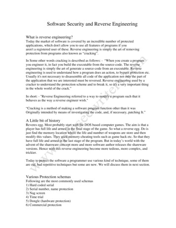
Page 91.1-CRANKSHAFTThe crankshaft, sometimes casually abbreviated to crank, is the part of an engine whichtranslates reciprocating linear piston motion into rotation. To convert the reciprocatingmotion into rotation, the crankshaft has "crank throws" or "crankpins", additional bearingsurfaces whose axis is offset from that of the crank, to which the "big ends" of the connectingrods from each cylinder attach.It typically connects to a flywheel, to reduce thepulsation characteristic of the four-stroke cycle, andsometimes a torsional or vibrational damper at theopposite end, to reduce the torsion vibrations oftencaused along the length of the crankshaft by thecylinders farthest from the output end acting on thetorsional elasticity of the metal.Figure 1.1 - Crankshaft1.1.1 - HISTORYThe crank and connecting rod was first used in Roman water mills of late antiquity. Theearliest evidence appears on a late 3rd century AD relief of a saw mill from Hierapolis, AsiaMinor, in which the mechanism converted the rotary motion of the waterwheel into the linearmovement of the saw blades.[1] Two 6th century saw mills excavated at Ephesus respectivelyGerasa, now Jordan, working with a very similar mechanism add to the growing body ofevidence that the Romans knew and applied the crank and connecting rod as part of amachine.In literature, crankshafts were described by Al-Jazari (who used it in two of his water-raisingmachines) in 1206, Konrad Kyeser (d. 1405), Francesco di Giorgio (1439–1502), Leonardoda Vinci (1452–1519), and Taqi al-Din in 1551. A Dutch "farmer" Cornelis Corneliszoon vanUitgeest also described a crankshaft in 1592. His wind-powered sawmill used a crankshaft toconvert a windmill's circular motion into a back-and-forward motion powering the saw.Corneliszoon was granted a patent for the crankshaft in 1597.1.1.2 - BEARINGSThe crankshaft has a linear axis about which it rotates, typically with several bearing journalsriding on replaceable bearing (the main bearings) held in the engine block. As the crankshaftundergoes a great deal of sideways load from each cylinder in a multicylinder engine, it mustbe supported by several such bearings, not just one at each end.High performance engines often have more main bearings than their lower performancecousins for this reason.
P a g e 101.1.3 - PISTONSTROKEThe distance the axis of the crank throws from the axis of the crankshaft determines thepiston stroke measurement, and thus engine displacement. A common way to increase thelow-speed torque of an engine is to increase the stroke. This also increases the reciprocatingvibration, however, limiting the high speed capability of the engine.1.1.4 - CONSTRUCTIONCrankshafts can be monolithic (made in a single piece) or assembled from several pieces.Monolithic crankshafts are most common, but some smaller and larger engines use assembledcrankshafts.BY FORGING AND CASTING:Crankshafts can be forged from a steel bar usually through roll forging or cast in ductile steel.Today more and more manufacturers tend to favor the use of forged crankshafts due to theirlighter weight, more compact dimensions and better inherent dampening. With forgedcrankshafts, vanadium microalloyed steels are mostly used as these steels can be air cooledafter reaching high strengths without additional heat treatment, with exception to the surfacehardening of the bearing surfaces. The low alloy content also makes the material cheaper thanhigh alloy steels. Carbon steels are also used, but these require additional heat treatment toreach the desired properties. Iron crankshafts are today mostly found in cheaper productionengines (such as those found in the Ford Focus diesel engines) where the loads are lower.Some engines also use cast iron crankshafts for low output versions while the more expensivehigh output version use forged steel.BY MACHINING:Crankshafts can also be machined out of a billet, often using a bar of high quality vacuumremelted steel. Even though the fiber flow (local inhomogeneities of the material's chemicalcomposition generated during casting) doesn’t follow the shape of the crankshaft (which isundesirable), this is usually not a problem since higher quality steels which normally aredifficult to forge can be used. These crankshafts tend to be very expensive due to the largeamount of material removal which needs to be done by using lathes and milling machines, thehigh material cost and the additional heat treatment required. However, since no expensivetooling is required, this production method allows small production runs of crankshafts to bemade without high costs.BY FATIGUE STRENGTH:The fatigue strength of crankshafts is usually increased by using a radius at the ends of eachmain and crankpin bearing. The radius itself reduces the stress in these critical areas, butsince the radii in most cases are rolled, this also leaves some compressive residual stress inthe surface which prevents cracks from forming.
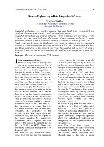
P a g e 11BY HARDENING:Most production crankshafts use induction hardened bearing surfaces since that method givesgood results with low costs. It also allows the crankshaft to be reground without having toredo the hardening. But high performance crankshafts, billet crankshafts in particular, tend touse nitridization instead. Nitridization is slower and thereby more costly, and in addition itputs certain demands on the alloying metals in the steel, in order to be able to create stablenitrides. The advantage with nitridization is that it can be done at low temperatures, itproduces a very hard surface and the process will leave some compressive residual stress inthe surface which is good for the fatigue properties of the crankshaft. The low temperatureduring treatment is advantageous in that it doesn’t have any negative effects on the steel, suchas annealing. With crankshafts that operate on roller bearings, the use of carburization tendsto be favored due to the high Hertzian contact stresses in such an application. Like nitriding,carburization also leaves some compressive residual stresses in the surface.BY COUNTERWEIGHTS:Some expensive, high performance crankshafts also use heavy-metal counterweights to makethe crankshaft more compact. The heavy-metal used is most often a tungsten alloy butdepleted uranium has also been used. A cheaper option is to use lead, but compared withtungsten its density is much lower.Figure 2 - CRANKSHAFT MADE OF AISI 1045 PLAIN CARBON STEEL
P a g e 121.2 -AISI 1045PLAIN CARBON STEELAISI 1045CategorySteelClassCarbon steelTypeStandardDesignations France: AFNOR XC 42 TS , AFNOR XC
Metallography done in as received and heat treated form in different magnifications, Metal composition analysis i.e. Spectroscopy (XRF) done in MMD XRF lab and from PSM, Steel grade identification with the help of hardness, microstructures, and composition. Moreover the report contains a comprehensive knowledge about all the steps