Transcription
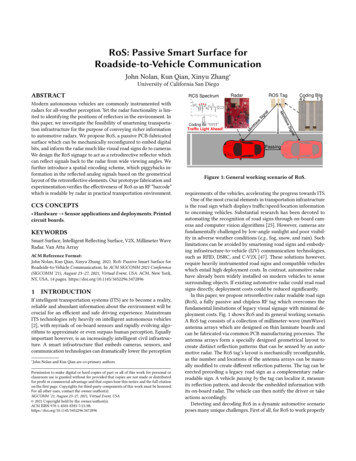
RoS: Passive Smart Surface forRoadside-to-Vehicle CommunicationJohn Nolan, Kun Qian, Xinyu Zhang University of California San DiegoABSTRACTModern autonomous vehicles are commonly instrumented withradars for all-weather perception. Yet the radar functionality is limited to identifying the positions of reflectors in the environment. Inthis paper, we investigate the feasibility of smartening transportation infrastructure for the purpose of conveying richer informationto automotive radars. We propose RoS, a passive PCB-fabricatedsurface which can be mechanically reconfigured to embed digitalbits, and inform the radar much like visual road signs do to cameras.We design the RoS signage to act as a retrodirective reflector whichcan reflect signals back to the radar from wide viewing angles. Wefurther introduce a spatial encoding scheme, which piggybacks information in the reflected analog signals based on the geometricallayout of the retroreflective elements. Our prototype fabrication andexperimentation verifies the effectiveness of RoS as an RF “barcode”which is readable by radar in practical transportation environment.CCS CONCEPTS Hardware Sensor applications and deployments; Printedcircuit boards.KEYWORDSSmart Surface, Intelligent Reflecting Surface, V2X, Millimeter WaveRadar, Van Atta ArrayACM Reference Format:John Nolan, Kun Qian, Xinyu Zhang. 2021. RoS: Passive Smart Surface forRoadside-to-Vehicle Communication. In ACM SIGCOMM 2021 Conference(SIGCOMM ’21), August 23–27, 2021, Virtual Event, USA. ACM, New York,NY, USA, 14 pages. ONIf intelligent transportation systems (ITS) are to become a reality,reliable and abundant information about the environment will becrucial for an efficient and safe driving experience. MainstreamITS technologies rely heavily on intelligent autonomous vehicles[2], with myriads of on-board sensors and rapidly evolving algorithms to approximate or even surpass human perception. Equallyimportant however, is an increasingly intelligent civil infrastructure. A smart infrastructure that embeds cameras, sensors, andcommunication technologies can dramatically lower the perception JohnNolan and Kun Qian are co-primary authors.Permission to make digital or hard copies of part or all of this work for personal orclassroom use is granted without fee provided that copies are not made or distributedfor profit or commercial advantage and that copies bear this notice and the full citationon the first page. Copyrights for third-party components of this work must be honored.For all other uses, contact the owner/author(s).SIGCOMM ’21, August 23–27, 2021, Virtual Event, USA 2021 Copyright held by the owner/author(s).ACM ISBN 52296.3472896RCS SpectrumRadarROS TagCoding Bits4213Coding Bit 1111Traffic Light Ahead!PassingFigure 1: General working scenario of RoS.requirements of the vehicles, accelerating the progress towards ITS.One of the most crucial elements in transportation infrastructureis the road sign which displays traffic/speed/location informationto oncoming vehicles. Substantial research has been devoted toautomating the recognition of road signs through on-board cameras and computer vision algorithms [25]. However, cameras arefundamentally challenged by low-angle sunlight and poor visibility in adverse weather conditions (e.g., fog, snow, and rain). Suchlimitations can be avoided by smartening road signs and embodying infrastructure-to-vehicle (I2V) communication technologies,such as RFID, DSRC, and C-V2X [47]. These solutions however,require heavily instrumented road signs and compatible vehicleswhich entail high deployment costs. In contrast, automotive radarhave already been widely installed on modern vehicles to sensesurrounding objects. If existing automotive radar could read roadsigns directly, deployment costs could be reduced significantly.In this paper, we propose retroreflective radar readable road sign(RoS), a fully passive and chipless RF tag which overcomes thefundamental limitations of legacy visual signage with minimal deployment costs. Fig. 1 shows RoS and its general working scenario.A RoS tag consists of a collection of millimeter-wave (mmWave)antenna arrays which are designed on thin laminate boards andcan be fabricated via common PCB manufacturing processes. Theantenna arrays form a specially designed geometrical layout tocreate distinct reflection patterns that can be sensed by an automotive radar. The RoS tag’s layout is mechanically reconfigurable,as the number and locations of the antenna arrays can be manually modified to create different reflection patterns. The tag can beerected preceding a legacy road sign as a complementary radarreadable sign. A vehicle passing by the tag can localize it, measureits reflection pattern, and decode the embedded information withits on-board radar. The vehicle can then notify the driver or takeactions accordingly.Detecting and decoding RoS in a dynamic automotive scenarioposes many unique challenges. First of all, for RoS to work properly
SIGCOMM ’21, August 23–27, 2021, Virtual Event, USAand effectively with automotive radars, the RoS tag must be easily detectable in spite of the vehicle’s varying viewing angles anddistances. To increase the azimuth field-of-view (FoV), we use VanAtta arrays (VAAs) [49] as a fundamental building block for the tag.The VAAs retroreflect mmWave signals in the azimuth plane, i.e.,radar signals that impinge on the VAAs will be reflected back to theemitter. With VAAs, the RoS tag can create a quasi-omnidirectionalreflection pattern and hence an electrically wide angular view. To increase the reading distance, RoS stacks multiple VAAs vertically toincrease its overall reflectivity. The stacking of VAAs unfortunately,creates an unwanted beamforming effect where the beamwidthalong the vertical dimension can become extremely narrow. Consequently, minor height misalignment between the radar and thetag may result in extremely weak reflections and hence, decodingfailure. To mitigate the impact of such misalignment, we introducean elevation beam shaping mechanism which can synthesize widerelevation beams without impacting the retroreflectivity on the azimuth plane. The beam shaping is achieved by treating the VAAswithin a stack as individual antenna “elements”, and applying a setof pre-determined phase weights on them. The phase weighting isin term created by optimizing the relative lengths and layouts ofthe transmission lines (TLs) within each VAA.The second design challenge lies in interference due to background reflections. In the automotive environment, a plethora ofother objects, e.g., pedestrians and street lamps, can easily overwhelm the return signal from an RoS tag due to their large sizeand strong reflectivity. To filter out such background interference,we design a polarization switching VAA (PSVAA) for the tag, whichalters the polarization of the incident signals to an orthogonalpolarity while reflections from ordinary roadside objects remainintact. With this measure, the radar can easily single out the tag’sreflections and suppress the environmental impact.Third, it is non-trivial to encode information in a deterministicway using a passive mmWave tag alone. A straightforward encodingmethod is to print random metallic geometries on the tag, which canbe mapped to certain radiation patterns using a machine learningmodel [28]. However, this method loses the retroreflective propertyand its non-explainable models have no performance guarantees.In other words, it is unclear how reliably the different symbols canbe discriminated by the radar and how many bits of information itcan actually encode. In RoS, we overcome such limitations througha novel spatial coding scheme. We build a deterministic modelwhich establishes the relationship between the geometrical layoutof multiple PSVAAs and the corresponding reflection pattern. In thisway, the RoS tag can encode information by simply positioning theVAAs following our model, and the radar can decode data bits bysampling the reflection signal strengths across multiple locations.Finally, it is challenging to accurately measure the reflectionpattern of a tag in the automotive scenario with a moving radar. Toovercome this challenge, RoS leverages the self-tracking capabilitiesof modern vehicles to obtain a coarse estimation of the relative tagradar position. It further uses two features, i.e., point cloud size andreflection loss, to discriminate the tag from other objects. The radarcan then beamform its signals to consistently “spotlight” on thetag.We have fabricated RoS tags and conducted extensive field experiments with TI’s experimental mmWave radar [22]. AlthoughJohn Nolan, Kun Qian, Xinyu Zhangthe radar has a relatively low transmit power and low sensitivity,the decoding SNR of RoS consistently exceeds 14 dB in typicalscenarios, which translates into a bit error rate below 0.6%. TheRoS tag can be reliably decoded by the radar at a distance of up to6 m, which fits common transportation scenarios where a vehiclepasses by the tag along a multi-lane road.In summary, the main contributions of RoS include:(i) Fully passive retroreflective smart surface comprised of an arrayof VAAs. We have designed a passive chipless tag that is retroreflective for 77-81 GHz automotive radar signals. Owing to the novelpolarization switching and elevation beam shaping mechanisms,our RoS tag can be reliably detected by a radar in practical roadwayconditions.(ii) Spatial coding scheme. We design a novel spatial codingscheme that exploits the deterministic relation between the tag’sgeometrical layout and its reflection pattern. We further introducemechanisms to enable the radar to accurately measure the tag’sreflection pattern in a dynamic automotive environment.(iii) Implementation and experimental validation. We have implemented RoS using the standard PCB fabrication process whichallows for mass production and reconfiguration of the signage.Our experiments verify the feasibility and accuracy of RoS, and itsusefulness as a new component in ITS.2RELATED WORKWireless I2V communications. A rich literature exists on wireless communications between infrastructure and vehicles (I2V)which primarily focuses on improving efficiency and reliability.DSRC and cellular C-V2X represent two mainstream I2V technologies. Both are witnessing limited deployment due to the cost ininstrumenting the vehicles and upgrading the base stations. Electronic toll collection systems (E-ZPass) have been deployed onmany roadway intersections and traffic hubs. E-ZPass consists of areader embedded within transportation infrastructure that queriesa battery-powered RFID tag mounted on a vehicle. Recent workadapts RFID localization technologies to position vehicles withE-ZPass onboard [1]. RoS differs from conventional I2V in thatthe roadside infrastructure is fully passive and does not requirededicated radio hardware. The main downside of RoS however, liesin that it only encodes a fixed amount of information similar toconventional road signs.Vision based technologies for road-to-vehicle communication. Our work is motivated by the growing interest in ITSwhich automates roadway infrastructure and vehicles to improveefficiency and safety. Market solutions for such services alreadyexist, including smart streetlights for parking spot checking [8],smart intersections that can monitor vehicle density and controltraffic lights [10], etc. These solutions require a smart camera to capture and process roadway status information. On-board computervision technologies have also been widely explored to assist driversby reducing missed road-signs and ultimately reduce accidents [25].These technologies however, are plagued by variable lighting conditions, sign orientation, sign aging, shadows of near-by objects,and adverse weather conditions [7, 14].To improve visibility, road signs today typically use a retroreflective coating and some even install LED lights. LEDs can be
RoS: Passive Smart Surface for Roadside-to-Vehicle Communicationfurther renovated to modulate information which can be capturedand decoded by on-vehicle cameras [23]. RetroI2V [59] exploitsvisible light backscatter communication in the form of an activeroad sign that can modulate the polarization of the vehicle’s LEDheadlight and reflect the modulated signals to convey information.Such systems still entail heavy instrumentation of both infrastructure and vehicles. In addition, they bear many of the same intrinsiclimitations as camera vision, i.e., vulnerability to adverse weatherconditions, although their detection range may be longer due tothe use of high dynamic range photodiode sensors.Chip and chipless RFID. RFID technologies have proliferatedresearch areas such as wireless communications, energy harvesting,object tracking, human-object interaction, etc. [16, 30, 39, 48, 58].An RFID system comprises of an interrogating reader and a tag witha RFID chip that is responsible for storing data and backscatteringsignals. In [17, 32, 37], RFID tags are used to inventory road signsand land marks. Vehicles with RFID readers can detect these tagsand decode information of road signs. Although RFID tags are lowcost and have high data encoding capabilities, it requires vehiclesto mount expensive RFID readers. In contrast, mmWave radars arealready abundant on vehicles today and are envisioned to be reusedwith mmWave tags at low cost. In addition, due to large antennasizes in UHF band, it is difficult to realize retro-directive RFID tags.Consequently, interference will become a daunting challenge inareas with densely populated vehicles and tags. Ultra-low powerdesigns using power harvesters [38, 50] can be used to design passive RFID tags that modulate the backscattered mmWave signal.However, with a required input power about 2 dBm, these ultra-lowpower designs would have severely limited communication rangeat mmWave band.Chipless RFID can be considered as an RF barcode, manufacturedthrough PCB printing or even inkjet printing [21] which eliminatesthe IC cost. Chipless RFID tags can encode information in thefrequency or time domain. A common frequency domain techniqueis to use notch filters that attenuate specific frequency bins tocreate unique identification signatures [5, 16, 24, 40]. Time domainencoding generally inscribes information by modulating the timingof pulses reflected back to the interrogator. Some examples includesurface-acoustic-wave (SAW) tags [41] or delay lines [51]. Despitethe low-cost, chipless tags have a major drawback–they generallyoperate in smaller interrogation zones and have limited informationencoding capabilities compared to the IC tag variants. RoS aimsto bring the benefits of fully passive, chipless RFID tags into theautomotive sensing domain. To this end, RoS renovates the tagdesign in two unique ways: (i) It leverages an array of retro-directiveVAAs to improve the reliability, reading range, and angular field-ofview. (ii) It utilizes a scalable spatial domain encoding mechanismto embed information in the RCS of the tag. Besides, RoS enables aradar to interrogate the tag in practical driving scenarios.Retro-directive antennas. Retro-directive antennas automatically redirect incoming signals back to the direction of the source.The most widely known retro-directive antenna is the cornerreflector [27]. An alternative is active phase conjugation using amixer or passive phase conjugation through VAAs. Since its invention in the 1960’s [49], VAAs have been researched extensively torealize retroreflection. Many VAA designs have been implementedin the microwave frequency band [44, 63] using a variety of antennaSIGCOMM ’21, August 23–27, 2021, Virtual Event, USAstructures such as slots [33], rings [45] or patch [3].The electromagnetic research literature has explored ways ofcombining retro-directive antenna designs with information encoding capabilities [27, 62]. In [62], information is stored in thefrequency domain through the use of surface notch filters to attenuate specific frequencies creating a spectrum signature. In [53],the reflected signal phase is modulated by varying transmissionline lengths or by frequency shifting the incident signal as in[26]. MmWave frequencies create new challenges for passive retrodirectors. Notch filter becomes impractical because of the difficultyin achieving large filter gain at high frequency bands [13], whereasphase based methods become extremely sensitive to multipath.In addition, many chipless backscatters have been developedusing RF switch modulation [20, 29, 31, 52]. In Millimetro [52],long-range and identifiable tags at 24 GHz are designed using VAAsand RF switches. At design frequencies such as 900 MHz and 24 GHz,reasonable RCS values can be achieved with minimal effort. However, translating these designs to the 77 GHz automotive radar band(i.e., 76-81 GHz) poses many challenges such as routing of the RFswitches and obtaining sufficiently high RCS levels. For example,in REITS [29], a total of 10 elements are used to create a VAA with5 pairs of antennas at 24 GHz. Moving to 77 GHz, this design wouldsuffer an RCS reduction of 25.85 dB. To overcome this issue, manymore antennas would be required, complicating the joint routingof transmission lines and RF switches.In contrast, RoS represents the first work to create an array ofretro-directive VAAs and use their spacial layout to encode data. TheRoS tag does not require discrete RF components and is designedto be directly detectable and decodable by an automotive radar.3 PRELIMINARY3.1 Electromagnetic Signature of ObjectsRadar signal propagation follows the well known round-trip pathloss model [35]:𝑃𝑡 𝐺 𝑡 𝐺 𝑟 𝜆 2 𝜎𝑃𝑟 (1)(4𝜋) 3𝑑 4where 𝑃𝑟 , 𝑃𝑡 , 𝐺𝑡 , 𝐺𝑟 , 𝜆, 𝑑 and 𝜎 are the received signal strength(RSS), transmit (Tx) signal power, Tx gain, receive (Rx) gain, signalwavelength in freespace, radar-to-object distance, and the RadarCross Section (RCS) of the object, respectively. This equation appliesto a typical monostatic radar, i.e., the Tx and Rx antennas are colocated.The RSS level 𝑃𝑟 is directly proportional to wavelength 𝜆, posinga challenge at mmWave frequencies which suffer from higher attenuation loss compared to microwave signals. Practical mmWaveradars often adopt MIMO beamforming, using multiple Tx/Rx antennas to increase the Tx/Rx gain to compensate for the largerattenuation.The RCS 𝜎 is a measure of an object’s detectability to a radaror how electrically large the object appears. Intuitively, RCS is theratio between the backscatter power per steradian in the directionof the radar and the power density that is intercepted by the object. The RCS area of an object does not necessarily overlap withthe physical cross-sectional area of that object. Instead, it dependsupon other factors such as material reflectivity, incident polarization, the radar’s viewing angles, and the directivity of the reflected
SIGCOMM ’21, August 23–27, 2021, Virtual Event, USAφ-ψφ-3ψφ-4ψ-4ψ -5ψφ-5ψ -ψ -2ψ -3ψ0123φ4φ 4πunless the radar stays at its normal direction.-35φ5RCS (dB)φ-2ψJohn Nolan, Kun Qian, Xinyu Zhang-404-45-5076φ 8π1277345678798081Frequency (GHz)Figure 2: Retroreflective Van Figure 3: RCS with differentAtta array (VAA).number of antenna pairs.signals caused by the object’s geometric shape. The RoS tag is essentially a smart surface whose RCS can be configured to convey bitsof information to the radar.3.2Object Detection with FMCW RadarCommercial mmWave radars typically transmit periodic frequencymodulated continuous wave (FMCW) signals [46] whose frequencyincreases linearly within each frame period. The radar can localizean object by estimating the distance and angle of arrival (AoA) ofreflected signals [57]. Distance estimation relies on counting thetime-of-flight, whereas AoA estimation relies on an array of Rxantennas. For an object whose distance is 𝑑𝑜 and AoA is 𝜃𝑜 , thebaseband signal of the 𝑘-th Rx antenna is [46]:𝑠 (𝑡, 𝑘) 𝑃𝑟 𝑒 4𝜋𝑖𝛾𝑑𝑜𝑐𝜃𝑜𝑡 2𝜋𝑖 𝑘𝛿𝑎 cos𝜆𝑒(2),where 𝛾 and 𝑐 denote the FMCW frequency slope and light speed. 𝛿𝑎represents the spacing between adjacent Rx antenna elements. Thefirst phase term is due to the propagation delay between the radarand the object, while the second is due to the relative propagationdelay between the Rx antennas.To estimate the distance of the object, an IFFT is applied overthe time domain 𝑡:𝑆 1 (𝑑, 𝑘) IFFT[𝑠 (𝑡, 𝑘)] 𝑃𝑟 𝛿 (𝑑 𝑑𝑜 )𝑒 2𝜋𝑖𝑘𝛿𝑎 cos 𝜃𝑜𝜆,(3)𝑆 1 (𝑑, 𝑘) achieves the maximum when 𝑑 𝑑𝑜 . To further estimatethe AoA of the object, the pseudo spectrum 𝑆 2 (𝑑𝑜 , 𝜃 ) is calculated by𝑘𝛿𝑎 cos 𝜃applying beamforming weights 𝑤𝑘 𝑒 2𝜋𝑖 𝜆to the frequencysamples 𝑆 1 (𝑑𝑜 , 𝑘):Õ𝑆 (𝑑𝑜 , 𝜃 ) 𝑤𝑘 𝑆 (𝑑𝑜 , 𝑘) 𝑃𝑟 𝛿 (𝜃 𝜃𝑜 ).(4)𝑘When 𝜃 𝜃𝑜 , the RSS 𝑃𝑟 can be approximated with 𝑆 (𝑑𝑜 , 𝜃𝑜 ).In practice, by recognizing peaks at different distances in 𝑆 1 (𝑑, 𝑘)and different AoAs for each distance in 𝑆 2 (𝑑𝑜 , 𝜃 ), the locations andreflected RSS of all prominent reflecting points can be estimated,generating a radar point cloud.The radar’s distance (range) resolution Δ𝑑 , and angle resolutionΔ𝜃 , is inversely proportional to the sampling bandwidth 𝐵 andnumber of antennas 𝑁𝑎 , respectively. For example, the recentlydeveloped TI automotive radar [22] has 𝐵 4 GHz and 𝑁𝑎 8,translating to Δ𝑑 3.75 cm and Δ𝜃 14.3 , respectively. It mightbe tempting to create a simple RF barcode by placing multiple metalpieces at predefined spots on a road sign to encode information,much like [28]. Unfortunately, given the coarse angle resolution, it isinfeasible for a radar to discriminate the pieces at a few meters away.The specular reflection will also render such a barcode undetectableMMWAVE RETROREFLECTIVE TAGDESIGNAn RoS road sign must be easily detectable by a radar within awide angular range, and be distinguishable from other irrelevantobjects on the road. In addition, its RCS should be large enough,so that the reflected signals can be detected by a passing-by radar,which can be a few lanes away from the curb. RoS innovates anarray of passive retroreflectors to meet these challenges, which willbe detailed in this section.4.1Retroreflection within the Azimuth PlaneA primer on Van Atta Array (VAA). RoS realizes the mmWaveretroreflector by extending the classical Van Atta Array (VAA)structure which was invented in the 1960’s [49]. As shown in Fig. 2,a basic VAA consists of a linear array of antenna elements withequal spacing of 𝜆2 . The symmetric elements (with respect to thecenter of the array) are interconnected by transmission lines (TLs).Signals received by each antenna are propagated through the TLsand re-radiated by its connected peer on the other end. Supposean incident far field wavefront induces a phase offset, 𝜓 , betweenadjacent antennas. The incident signal phase at the 𝑘-th antenna,relative to that at the 0-th antenna, is 𝑘𝜓 . By setting the lengths ofeach TL to differ by multiples of 𝜆𝑔 (i.e., the wavelength of the signalguided in TLs), a constant wrapped phase offset 𝜑 is introduced forall signals propagating through the TLs. Consequently, given thenumber of antennas 𝑁 , the 𝑘-th antenna receives and re-rediates thesignal from the (𝑁 1 𝑘)-th antenna, whose phase is 𝜑 (𝑁 1 𝑘)𝜓 .Its phase relative to the 0-th antenna is (𝜑 (𝑁 1 𝑘)𝜓 ) (𝜑 (𝑁 1)𝜓 ) 𝑘𝜓 , which is reversed compared to the phase of theincident signal arriving at it. In other words, the re-radiated signal issteered back to the direction of arrival, i.e., the VAA is retroreflective.VAA design choices for RoS. The use of multiple incident andre-radiation antennas essentially makes the VAA a passive beamforming reflector which focuses towards the interrogator. Ideally,the more antenna pairs in a VAA, the larger its RCS should be. However, the aforementioned VAA model assumes a single tone signalwhose guided wavelength is 𝜆𝑔 , whereas in RoS, the interrogatoris a radar with a wide bandwidth, and hence the difference of theguided wavelength across frequencies becomes non-negligible. Furthermore, more antenna pairs means a longer TL length and morepropagation loss which limits the RCS contribution of the outerantenna pairs. Thus, we analyze how to optimize the VAA designin RoS to account for these factors.Recall that the different TLs differ by multiples of 𝜆𝑔 . The radarsignals at different frequencies experience phase misalignmentwhen propagating through variable length TLs. Consequently, thephase misalignment becomes unavoidable as the length differencebetween TLs increases. Suppose the bandwidth and center frequency of the radar are 𝐵 and 𝑓𝑐 , and the maximum length difference between the shortest and longest TL is 𝛿𝑙 , the maximum phasemisalignment between the frequencies 𝑓𝑐 𝐵2 and 𝑓𝑐 𝐵2 , is 2𝜋 𝑐𝐵𝑔 𝛿𝑙 ,where 𝑐𝑔 is the signal propagation speed in the TLs. To avoid destructive interference between antenna pairs, the maximum phasemisalignment should be smaller than 𝜋2 , i.e., 2𝜋 𝑐𝐵𝑔 𝛿𝑙 𝜋2 .
-35-40-45-50Van -60-50-60Van AttaULAo-300306090-70-90oAzimuth ( )-60-300306090Azimuth ( )(b) Bistatic-30-40-50oAzimuth ( )(a) Monostatic-20PSVAAOriginal VAA-40RCS (dB)-30-35SIGCOMM ’21, August 23–27, 2021, Virtual Event, USARCS (dB)-30RCS (dB)RCS (dB)RoS: Passive Smart Surface for Roadside-to-Vehicle Communication(a) Tx/Rx with orthogonal polarization-60-90-60-300306090Azimuth (o)(b) Tx/Rx with same polarization-30-30-40-40RCS (dB)RCS (dB)Figure 4: Comparison of the RCS of Van Atta Array (VAA) and Figure 5: Comparison between the RCS of PSVAA and originalUniform Linear Array 090Azimuth ( o)(a) Tx/Rx with orthogonal polarization-70-90-60-300306090Azimuth ( o)(b) Tx/Rx with same polarizationarriving from different angles do not interfere with each other. Fig. 4bshowcases a scenario where a radar interrogates the VAA at anangle of 30 , while the RCS is measured at different azimuth angles.We see that the ULA reflects the signals towards the symmetricdirection ( 30 ), whereas the VAA redirects the signal back to theincoming angle. Although the VAA is imperfect and there existsleakage at other angles, the leaked signals are much weaker (513 dB lower), demonstrating that the interference of the VAA todirections other than the incident direction is negligible.Figure 6: RCS of PSVAA across the 76-81 GHz frequency band.4.2For a typical automotive radar with 𝐵 4 GHz, we have 𝛿𝑙 4.94𝜆𝑔 . Given that the total spacing between adjacent antenna pairsis 2 · 𝜆2 𝜆, the length difference of adjacent TLs, denoted as Δ𝐿,should be at least 𝜆 to avoid antenna overlap. Accordingly, sinceΔ𝐿 must be an integer multiple of 𝜆𝑔 and 𝜆𝑔 𝜆, the minimumΔ𝐿 needs to be 2𝜆𝑔 . Therefore, for RoS to retro-reflect automotiveradar signals, the optimal number of antenna pairs on each VAA is4.94𝜆⌈ 2𝜆 𝑔 ⌉ 3.𝑔Verifying the design choices. To verify the above design choices,we conduct experiments in Ansys HFSS, a 3D electromagnetic (EM)field simulator. We lay out VAAs with different number of antennapairs and simulate their RCS across the wide frequency band ofan automotive radar, i.e., 76-81 GHz. As shown in Fig. 3, the RCScontribution per antenna pair is maximized with 3 antenna pairsand marginally increases beyond that which matches the abovemodel. Thus, to maximize the utility in terms of RCS per antennapair, a VAA in RoS should have at most 3 antenna pairs.The ideal VAA model [49] assumes perfect lossless, point-scatterantennas and a single frequency. To verify the retroreflectivity ofthe VAA in the presence of practical wideband mmWave radarsignals, we conduct another HFSS simulation and compare the 6element VAA with a uniform linear array (ULA) of 6 patch antennaelements. The ULA can be considered as an ordinary reflectiveobject comprised of a few metal patches. Fig. 4a shows the measuredRCS when a monostatic radar passes by from different azimuthangles. We see that the VAA has a relatively flat RCS within afield-of-view (FoV) of approximately 120 , which verifies its retrodirective property. In contrast, the ULA acts like a specular reflector,and only responds with a strong RCS when the radar faces it straighton. Note that the FoV of the VAA or ULA cannot reach 180 sinceeach patch antenna element itself has a limited radiation angle.A side benefit of retroreflectivity is that interogating radar signalsSuppressing Background Interference withPolarization SwitchingUnlike active radios, the passive RoS tag reflects a similar amountof radar signal power as scattering objects in the environment, suchas poles, pedestrians, trees, etc. The background reflections caneasily interfere with the desired tag reflection and compromiseits detection performance. To address this challenge, we proposea polarization switching VAA (PSVAA) design. Most objects onthe road barely impact the polarization of incidental signals uponreflection [18]. Our PSVAA is designed to switch the polarity ofsignals orthogonally to make the signals reflected by the tag standout amid the background interference.We construct the PSVAAs by extending the basic design in Section 4.1. Specifically, we rotate half of the patch antenna elementsby 90 to create the second orthogonal polarization, as shown inFig. 7a. A slight drawback of the PSVAA is that only half of theelements re-radiate, in contrast to the original VAA where a pair ofconnected elements radiate in a symmetric manner. Consequently,the power of the signal reflected by a PSVAA is halved, and the RCSis reduced by 20 log10 (0.5) 6 dB. However, in Sec. 7.2, we showthat the benefit from polarization switching is more than 14 dB,which sufficiently compensates for the RCS loss.The PSVAA in RoS adopts a 4 layer PCB structure, as illustratedin the stackup in Fig. 7c. The top layer lays the patch antennas, followed by a ground layer below, a strip-line TL, and another groundlayer. Ne
visible light backscatter communication in the form of an active road sign that can modulate the polarization of the vehicle's LED headlight and reflect the modulated signals to convey information. Such systems still entail heavy instrumentation of both infrastruc-ture and vehicles. In addition, they bear many of the same intrinsic