Transcription
FOLDING STAIRWAYManual LeTourneau L1850 Wheel LoaderRear Mounted StairModel No.: PSA-L1850-FS- RFSerial No.: PSA-L1850-001 - Date Manufactured: Dec 2014PSA-L-1850 -FS-RF 12-12-14
FOLDING STAIRWAYLeTourneau L1850 Wheel LoaderRear Mounted StairCONTENTSPage 3Section 1 Installation and Mounting InstructionsInstallation Drawings:8Section 2 Recommended Maintenance Procedure9Section 3 Operating ProcedureSection 4 Drawings and Repair Parts lists104Assembly CompleteParts List124-1 Stair Access Frame and Mounting AssemblyParts List144-2 Stair AssemblyParts List164-3 Latch AssemblyParts List184-4 Hydraulic Cylinders & PlumbingParts ListHydraulic LayoutValve Diagram214-5 Power PackParts List254-6 Electrical ControlsWiring DiagramsInsert and Warning PagesPSA-L-1850 -FS-RF 12-12-14Pg. 2
FOLDING STAIRWAYLeTourneau L1850 Wheel LoaderRear Mounted StairSection 1 Installation Drawings Mounting Pl. Weldment PSA-L1850-BA-B01PSA-L-1850 -FS-RF 12-12-14Pg. 3
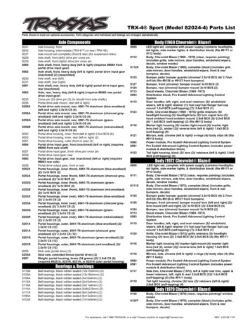
PSA-L-1850 -FS-RF 12-12-14After welding Mounting Plates (Item 5)to its indicated position,proceed with theinstallation of the Main Frame(PSA-FRA-A04) and bolt it with the 8 x M8x60 socket head capscrews.Once the frame is secure,proceed to install the stair and secure it with the 2 pinssupplied for this purpose.Install the Hydraulic ram and connect the hoses to the Power Pack2.3.Section 1 Installation Drawings Access Installed1.ProcedureFOLDING STAIRWAYLeTourneau L1850 Wheel LoaderRear Mounted StairPSA-L1850-BA-INSTNOTEFollow all on-site/Mine lifting and safety procedures when installing PSFSPg. 4
FOLDING STAIRWAYLeTourneau L1850 Wheel LoaderRear Mounted StairPSA-L-1850 -FS-RF 12-12-14PSA-L1850-BA-Access Sht. 1DETAIL BDETAIL ASection 1 Installation DrawingsPg. 5
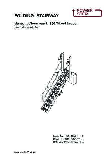
FOLDING STAIRWAYLeTourneau L1850 Wheel LoaderRear Mounted StairSection 1 Installation Drawings PSA-L1850-BA-Access Sht. 2STAIR SHOWN IN BOTH POSITIONSDEPLOYED AND STOWED58542322151204215414PSA-L-1850 -FS-RF 12-12-14Pg. 6
FOLDING STAIRWAYLeTourneau L1850 Wheel LoaderRear Mounted StairSection 1 Installation and Mounting Instructions (cont.)WARNINGRaising the POWER STEP platform by external means can create a vacuum in thehydraulic cylinder and create the opportunity to allow air into the hydraulic system,defeating the inherent safety features of the POWER STEP.This must be avoided, to maintain safe operation of the POWER STEP.In instances where the use of external means to raise the platform must be used,please follow the following instructions:Loosen hard plumbed hydraulic lines on cylinder side of lock valve on cylinder.Raise platform by available means.Note: Make necessary arrangements to collect displaced oil, and be aware that air entersthe piston side of the cylinder as platform is raised.Lock in raised position.Re-tighten hydraulic fittings.SECURE THE PLATFORM IN THE RAISED POSITION, MECHANICALLY, CHAIN &TAGOUT THE POWER STEPTo recommission the POWER STEP:Loosen hydraulic fittings on cylinder side of lock valve.Note: Collect displaced oil.Lower platform to lowest position, using alternate safety approved means, fully retractingcylinder. Ensure all personnel are clear of step radius.Operate electrical control switch to purge air from the hydraulic line systems, lock valveand cylinder.Tighten the hydraulic fittings either side of lock valves to restriction fittings.Cycle step unloaded several times to purge all air from hydraulic system.The Power Step will not operate correctly if there is any air in the hydraulic circuit (due tothe incorrect operation of the lock valve).NOTE.THE RELIEF PRESSURE OF THE POWERPACK IS TO BE SET TO 2800PSI.IF THE POWERPACK IS REPLACED,THIS RELIEF PRESSURE WILL NEED TO BERESET USING INLINE GAUGES.FAILURE TO DO SO MAY RESULT IN ACCIDENT OR INJURY.PSA-L-1850 -FS-RF 12-12-14Pg. 7
FOLDING STAIRWAYLeTourneau L1850 Wheel LoaderRear Mounted StairSection 2 Recommended Maintenance ProcedureDailyVisually check stairway and structure for damage, loose components,handrails, etc.Check for hydraulic oil leaks from hydraulic cylinders, plumbing and hoses.Notify the appropriate supervisor for any observed damage or malfunction.500 HoursGrease 2 grease nipples on hinge pinsCheck main mounting bolts for torque.Check hydraulic oil level in power pack and top up as necessary. (Stairway in raisedposition).Top up using same hydraulic oil as used in hydraulics of machine.Thoroughly check all electrical wiring for damage, replace as necessary.Repeat daily check as above5000 HoursChange hydraulic oil in tank of hydraulic power pack (5.0 litres)It is recommended that the same hydraulic oil be used in the power pack as thehydraulics of the machine.Check and inspect all main bolts on stairway system.Retorque if required.Repeat daily check as abovePSA-L-1850 -FS-RF 12-12-14Pg. 8
FOLDING STAIRWAYLeTourneau L1850 Wheel LoaderRear Mounted StairSection 3Operating ProcedureTo Lower Stairway (from the machine)Position machine in a level, safe area, away from the work face, whenever possible.Apply park brake and lower engine speed to idle.Check that the area below the Ladder Access System is clear of people andobstacles, and lower ladder by operating the two position electrical switch adjacentto the ladder, to the down position by pressing the switch down.Hold the switch in the down position until ladder is fully lowered.If the Machine is parked on uneven ground, the bottom of the stairway may touchthe ground before the ladder is in the fully lowered position.Should this occur, descend the ladder with caution.To Raise StairwayAscend the ladder onto the landing of the Loader.Ensure the area around the ladder is clear of people and standing to the side, clearof the area the handrails and ladder raises into, operate the electrical switch to theraise position (up).Hold the switch in the up position until the ladder is in the fully raised position.The ladder is now raised and stored.OPERATING NOTESNOTE: FLOW CONTROL VALVE ADJUSTMENT:The valve should be positioned to restrict the flow and speed of the Power Step whenlowering. Adjust the knob on top of the valve by turning left or right (clockwise) when thestep is being lowered, until it is lowering at a safe and reasonable speed.When it is adjusted, lock the adjusting knob by tightening the grub screw located on theside of the knob.NOTE: MAGNETIC 'GO' SWITCH ADJUSTMENT:The switch target trigger area is located on the opposite side and end from the cable entrypoint on the switch. Once it is mounted to the switch bracket, adjust the switch in or outfrom the stair steel trigger point, to be within 3mm - 10mm from touching each other whenthe stair is in the desired rest position.[DO NOT EXCEED 10mm DISTANCE BETWEEN THE SWITCH AND STRIKER PLATE].Test by raising and lowering the Power Step a couple of times and adjust again ifnecessary.PSA-L-1850 -FS-RF 12-12-14Pg. 9S
FOLDING STAIRWAYLeTourneau L1850 Wheel LoaderRear Mounted StairSection 4Assembly CompletePSA-L-1850 -FS-RF 12-12-14PSA-L1850-FS-RFPg. 10
FOLDING STAIRWAYLeTourneau L1850 Wheel LoaderRear Mounted StairSection 4 Assembly CompleteSee Drawing Page 11ITEM PART NO.PART NAMEQTYPSA-L1850-FS-RF ASSEMBLY COMPLETE11PS-FRA-A04ACCESS FRAME & MOUNTING ASSEMBLY12PS-STR-A16STAIR ASSEMBLY13PS-LOC-A07LATCH ASSEMBLY14PS-62998-AHPS- 62997-AHYDRAULIC CYLINDER (Stair)HYDRAULIC CYLINDER (Latch)15PS-80103A-SLDPOWER PACK1PSA-L-1850 -FS-RF 12-12-14Pg. 11
FOLDING STAIRWAYLeTourneau L1850 Wheel LoaderRear Mounted StairSection 4.1 Access Frame and Mounting Assembly PS-FRA-04See Parts List Pg. 12Does not include Items 2, 2A & 2B26PSA-L-1850 -FS-RF 12-12-14Pg. 12
FOLDING STAIRWAYLeTourneau L1850 Wheel LoaderRear Mounted StairSection 4.1 Access Frame and Mounting Assembly PS-FRA-A04See Drawing Page 11 Does not include Items 2, 2A & 2BItem Part No.Part NameQty1PS-FRA-A04STAIR ACCESS FRAME ASSEMBLY12PS-FRA-C56ACCESS MOUNT BASE12APS-FRA-C55SIDE STIFFENER PLATE12BPS-FRA-C54BOTTOM STIFFNER PLATE13PS-STR-B17TOP LANDING TREAD14PS-FLR-C29MESH FLOOR15PS-63009-BHARDENED BUSH16PS-LOC-B06STRIKER-LEFT SIDE17PS-LOC-B07STRIKER-RIGHT SIDE18PS-LOC-C46BUFFER LEADER PLATE29PS-LOC-C36MANUAL RELEASE LEVER110PS-P30-009PIVOT PIN211PS-LOC-C35LATCH BUSH412PS-LOC-C29WASHER113PS-40002LATCH LEVER BUFFER Mackay114PS-61006GREASE NIPPLE M6215CPS-M16X40ZPBOLT-M16 x 404SOCKET HEAD M16 x 40415A CPS-M16X40SC16CPS-M12X30ZPBOLT-M12 x 30817CPS-M10X60ZPBOLT-M10 x 60 CAP SCREW118CPS-M10X25SCBOLT-M10 x 25 CAP SCREW419CPS-M10X20ZPBOLT-M10 x 20820CPS-M10X16ZPBOLT-M10 x 16421CPS-M6X50ZPBOLT-M6 x 50222CPS-M5X50ZPBOLT-M5 x -M5WHWASHER-HARDENED-M58PSA-L-1850 -FS-RF 12-12-14Inc. 21,24,24,14Pg. 13
FOLDING STAIRWAYLeTourneau L1850 Wheel LoaderRear Mounted StairSection 4-2 Stair AssemblyPSA-STR-A16See Parts List Page 141716PSA-L-1850 -FS-RF 12-12-14Pg. 14
FOLDING STAIRWAYLeTourneau L1850 Wheel LoaderRear Mounted StairSection 5-2 Stair AssemblyPSA-STR-A16See Drawing Page 13Item Part No.Part NameQty1APS-STR-B11-03STAIR STILE - LEFT HAND11BPS-STR-B11-04STAIR STILE - RIGHT HAND12PS-HRI-B06-03STAIR HANDRAIL - LEFT HAND13PS-HRI-B06-04STAIR HANDRAIL - RIGHT HAND14PS-STR-B10-01STAIR ACTUATOR BEAM15PS-STR-C21-01STAIR TREAD86PS-STR-C21-02STAIR TREAD -TOP17PS-P30-008-02PIVOT BUSH28PS-63009BBUSH- (Actuator Beam)19PS-STR-C62BUMPER PAD (Rubber)210PS-34108BUFFER-RUBBER211PS-23637WASHER PLATE812PS-FRA-C42STRIKER213CPS-M16X60ZPBOLT-M16 x 60 CAP SCREW214CPS-M12X50PBOLT-M12 x 50815CPS-M12X35PBOLT-M12 x 356416CPS-M8X40ZPBOLT-M8 x 40 M126419CPS-M12WHWASHER-HARDENED-M12144PSA-L-1850 -FS-RF 12-12-14Pg. 15
FOLDING STAIRWAYLeTourneau L1850 Wheel LoaderRear Mounted StairSection 4-3Latch AssemblyPSA-LOC-A07See Parts List Pg.15PSA-L-1850 -FS-RF 12-12-14Pg. 16
FOLDING STAIRWAYLeTourneau L1850 Wheel LoaderRear Mounted StairSection 4-3 Latch AssemblyPSA LOC- A07See Drawing Page 15Item Part No.Part NameQty1PS-62997CYLINDER12PS-LOC-B03LATCH FRAME13PS-LOC-B05LATCH WRIST FABRICATION14PS-LOC-B04ACTUATOR ARM FABRICATION15PS-LOC-C23BOLT LINK26PS-LOC-C24LOCK PIN27PS-LOC-C35LATCH BUSH (Polyurethane)68PS-LOC-C31WRIST -C49ANTI-RATTLE WASHER212PS-S245LATCH BUSH-(WRIST PLATE)213CPS-M10X70RPROLL PIN114CPS-M12X100ZPBOLT-M12 x 100115CPS-M12X55ZPBOLT-M12 x 55316CPS-M12X35ZPBOLT-M12 x 35617CPS-M10X70ZPBOLT-M10 x ED-M104PSA-L-1850 -FS-RF 12-12-14Refer Pg 20Pg. 17
FOLDING STAIRWAYLeTourneau L1850 Wheel LoaderRear Mounted StairSection 4-4 Hydraulic Cylinder & Plumbing Cyl. P/No. PS- 62998-AHNOTE: HYDRAULIC CYLINDER ASSEMBLY P/No PS- 62998-AH includes Part No.s 1 to 11Item Part No.1Part NameQtyPS-62998-AHHYDRAULIC CYL. (with hard plumbing )1PS-62998-HPKHARD PLUMBING KIT11APS-62998-AHYDRAULIC CYLINDER 2 1/2”11BPS-63009-PPIN - CYLINDER21SPS-63103SEAL KIT (Not shown)12PS-63201VALVE - PILOT OPERATED LOCKING13PS-61159FITTING - ELBOW-9/16” JIC14PS-61154FITTING - ELBOW- O RING 1/4BSPPx9/16”JIC15PS-61157FITTING - O RING 1/4BSPPx 9/16”JIC26PS-61158-5MMFITTING - 5mm RESTRICTION 90 DEG17PS61163REDUCER JIC x BSPP28PS-61160TUBE (Cut to suit) 510mm19PS-61147FERRULES210PS-61158-1MMFITTING - 1MM RESTRICTION 90 DEG111PS-61145FITTING- 9/16”JIC SWIVEL112PS-60051-3.5MHOSE- HYDR. ( 7/16”JIC SWIVEL FITTING)113PS-60050-3.5MHOSE- HYDR. ( 9/16”JIC SWIVEL FITTING)1PSA-L-1850 -FS-RF 12-12-14CYL. ENDROD ENDPg. 18
FOLDING STAIRWAYLeTourneau L1850 Wheel LoaderRear Mounted StairSection 4-4 Hydraulic Cylinder & Plumbing Latch PS- 62997-A1671A345Item Part No.1PS-629971A PS-62997-PPart NameQtyHYDRAULIC CYLINDER - LATCH1CYLINDER PIN22PS-62997-SKSEAL KIT-LATCH (NOT SHOWN)13PS-60051-5M 9/16HOSE-HYDR. (9/16”JIC ST. SWIVEL 5M)14PS-60050-1.8M 7/16HOSE-HYDR. (7/16”JIC ST. SWIVEL 5M)15PS-61150ELBOW-FITTING 7/16”16PS-61152ELBOW-FITTING 9/16”17PS-61159ELBOW-FITTING 9/16”1PSA-L-1850 -FS-RF 12-12-14Pg. 19
FOLDING STAIRWAYLeTourneau L1850 Wheel LoaderRear Mounted StairSection 4-4Hydraulics(Valve Diagram)Double Acting Hydraulic System withdirectional Control Valve and CylinderLock Valve5mmPSA-L-1850 -FS-RF 12-12-141mmPg. 20
FOLDING STAIRWAYLeTourneau L1850 Wheel LoaderRear Mounted StairSection 4-5 Power PackPS- 80103A-SLDSee Parts List Pg 222913266View B525View A10111699A24288A733A307A14Hoses showndotted627412PSA-L-1850 -FS-RF 12-12-14Pg. 21
FOLDING STAIRWAYLeTourneau L1850 Wheel LoaderRear Mounted StairSection 4-5 Power PackPS-80103A-SLDSee Parts List Pg 22281810163111171914123233View A1524239219A2037NOTE.36View BTHE RELIEF PRESSURE OF THE POWERPACK IS TO BE SET TO 2800PSI.IF THE POWERPACK IS REPLACED,THIS RELIEF PRESSURE WILL NEED TO BERESET USING INLINE GAUGES.FAILURE TO DO SO MAY RESULT IN ACCIDENT OR INJURYPSA-L-1850 -FS-RF 12-12-14Pg. 22
FOLDING STAIRWAYLeTourneau L1850 Wheel LoaderRear Mounted StairSection 4-5 Power PackPS-80103A-SLDSee Photos Pg 20 & 21Item Part No.Part NameQty1PS-80103A-SLDPOWER PACK ASSEMBLY12PS-21107-METALMOTOR ENCLOSURE- SEALED ST/ST13PS-80103APOWER PACK13APS-80103-CLAMPCLAMP ELECTRIC MOTOR13BPS-84201-100HEAT SENSOR14PS-82415AUDIBLE ALARM15PS-84214BRIDGE RECTIFIER16PS-82492SOLENOID 24V START MOTOR17PS-60051-900MM 9/16”HYDR. HOSES 9/16”JIC STRAIGHT SWIVEL17APS-60050-900MM 7/16”HYDR. HOSES 7/16”JIC STRAIGHT SWIVEL18PS-61152HYDRAULIC FITTING 9/16”18APS-61150HYDRAULIC FITTING 7/16”19PS-61176HYDRAULIC FITTING 7/16”19APS-61177HYDRAULIC FITTING 9/16”110PS-84213135A CIRCUIT BREAKER111PS-842125A CIRCUIT BREAKER112PS-84303ISOLATION SWITCH113PS-1712080SEALED WIRING BOX114PS-73012TOGGLE SWITCH KIT115PS-82493BATTERY FEED STUDS216PS-HD10-5-16P5 PIN SOCKET117PS-41010DECAL-Battery Isolation118PS-41011DECAL-Battery Supply C/B-135A119PS-41012DECAL-Controller Supply C/B-10A120PS-41013DECAL-Battery Supply-PosItive121PS-41014DECAL-Battery DECAL HYDRAULIC-HOSES124PS-41041DECAL OIL TANK125PS-41019DECAL BRIDGE RECTIFIER126PS-41017DECAL SOLENOID127PS-41018DECAL ALARM128PS-41016DECAL RAISE/LOWER SWITCH129PS-73010RUBBER BOOT RED6PSA-L-1850 -FS-RF 12-12-14Pg. 23
FOLDING STAIRWAYLeTourneau L1850 Wheel LoaderRear Mounted StairSection 4-5 Power PackPS-80103A-SLDSee Photos Pg 20 & 21Item Part No.Part NameQty30PS-73009RUBBER BOOT BLACK331PS-HD10-3-16P3 PIN SOCKET (PARK BREAK)132PS-HD10-5-16P5 PIN SOCKET (AUTO-RAISE)133PS-41032DECAL AUTO-RAISE SOCKET134PS-60051-3.5MHYDRAULIC HOSE 9/16” x 3.5M1Not Shown35PS-60050-3.5MHYDRAULIC HOSE 7/16” x 3.5M1Not Shown36PS-63202AVALVE FITTING (FLOW CONTROL VALVE)137PS-HD10-5-16P5 PIN SOCKET1PSA-L-1850 -FS-RF 12-12-14Pg. 24
FOLDING STAIRWAYLeTourneau L1850 Wheel LoaderRear Mounted StairSection 4-6 Electrical ControlsControl Pendant SwitchMounted on HandrailProximity Switch Assembly1Mounted on Fixed Landing56Cab Harness & EquipmentRefer Wiring Harness Drawings7PSA-L-1850 -FS-RF 12-12-144238Pg. 25
FOLDING STAIRWAYLeTourneau L1850 Wheel LoaderRear Mounted StairSection 4-6 Electrical ControlsSee Page 23Item Part No.Part NameQty1PS-73013CONTROL PENDANT SWITCH12PS-73013-BCONTROL PENDANT BRACKET13PS-77005HAND RAIL SWITCH HARNESS14PS-77009ARAUTO RAISE HARNESS15PS-77004CABIN TO SWITCH HARNESS16PS-75430PROXIMITY SWITCH27PS-77002CABIN BOX LED LIGHT INDICATOR18PS-77003WIRING HARNESS IN CABIN1Optional only1 X OptionalWARNINGLOW VOLTAGE BATTERIES WILL HARM THE FUNCTIONOF THE POWER PACK AND THE CONTROL SWITCHES.DAMAGE RESULTING DUE TO LOW VOLTAGEBATTERIES WILL VOID WARRANTY ON ALLELECTRICAL COMPONENTS.PSA-L-1850 -FS-RF 12-12-14Pg. 26
FOLDING STAIRWAYLeTourneau L1850 Wheel LoaderRear Mounted StairWiring Diagrams Page 1WIRING HARNESSSection 4-6 Electrical ControlsPSA-L-1850 -FS-RF 12-12-14Pg. 27
FOLDING STAIRWAYLeTourneau L1850 Wheel LoaderRear Mounted StairSection 4-6 Electrical ControlsPSA-L-1850 -FS-RF 12-12-14Wiring Diagrams Page 2Pg. 28
FOLDING STAIRWAYLeTourneau L1850 Wheel LoaderRear Mounted StairSection 4-6 Electrical ControlsWiring Diagrams Page 3WIRING HARNESS 1PSA-L-1850 -FS-RF 12-12-14Pg. 29
FOLDING STAIRWAYLeTourneau L1850 Wheel LoaderRear Mounted StairSection 4-6 Electrical ControlsWiring Diagrams Page 4WIRING HARNESS 2PSA-L-1850 -FS-RF 12-12-14Pg. 30
INSERT ONLYGround Access Up/Down Switch Kit(with harness and “Y” harness joint)PS-77020PSA-L-1850 -FS-RF 12-12-14Pg. 31
WARNINGDO NOT REPAIR, STRAIGHTEN, REWELD OR ATTEMPT TO FIX THE LADDERAFTER IT SUSTAINED ANY DAMAGECONTACT POWER STEP OR ITS LOCAL AREA REPRESENTATIVE TOREQUEST A REPLACEMENT LADDERIF THE LADDER MATERIAL IS BENT, TWISTED OR CRACKED YOU MUSTREPORT THE INCIDENT TO POWER STEP SO PROPER REMEDIAL ACTION ISTAKEN TO ADDRESS THE DAMAGEPOWER STEP DESIGNED AND FABRICATED THIS PRODUCT UNDERSPECIFIC STANDARDS AND GUIDELINES; ANY CHANGES ORMODIFICATIONS WILL JEOPARDISE MATERIAL PROPERTIES AND SAFETYOF THE PRODUCTCONTACTPOWER STEP (AUSTRALIA) PTY LTDTEL: 61 7 32773977FAX: 61 7 32773994EMAIL: sales@powerstep.com.auPSA-L-1850 -FS-RF 12-12-14Pg. 32
LeTourneau L1850 Wheel Loader Rear Mounted Stair Section 1 Installation Drawings Access Installed PSA-L1850-BA-INST Procedure 1. Af ter welding Mounting Plates (Item 5)to it s indicated position,proceed with the inst allation of the Main Frame(PSA-FRA-A04) and bolt it with the 8 x M8x60 socket head cap screws. 2. Once the frame is secure .