Transcription
TN-102Sep-2017TECHNICAL NOTEOverview of IRIG-B Time CodeStandardIntroductionSummaryThe IRIG-B time protocol is widely used by electricutilities, industrials, and others to ensure precisetime synchronization of power system devices, suchas breakers, relays and meters.This document describes the protocol, givesexamples of Cyber Sciences products that supportIRIG-B, and describes how this legacy protocol isbeing replaced by PTP (Precision Time Protocol perIEEE 1588) in modern power system applications.IRIG STANDARD 200-04The IRIG time codes were originally developed by the Inter-Range InstrumentationGroup (IRIG), part of the Range Commanders Council (RCC) of the US Army. The standard was first published in 1960 and has been revised several times by the Telecommunications and Timing Group (TTG) of the RCC. The latest version is IRIG standard200-04, “IRIG Serial Time Code Formats,” updated in September, 2004.Available FormatsAlthough the “IRIG-B” time code is best known, the standard actually defines a familyof rate-scaled serial time codes. The six code formats use different pulse rates, or bitrates, as shown in the table below.IRIG Time Code FormatsTELECOMMUNICATIONSAND TIMING GROUPFormatPulse Rate (or Bit Rate)Index Count IntervalIRIG-A1000 PPS (pulse per second)1 msIRIG-B100 PPS10 msIRIG-D1 PPM1 minuteIRIG-E10 PPS100 msIRIG-G10000 PPS0.1 msIRIG-H1 PPS1 secondIRIG STANDARD 200-04Time Code AttributesAll IRIG time code formats use pulse-width coding. A “binary 1” pulse has a durationof 50% of the index count interval, and a “binary 0” pulse has a duration of 20% ofthe index count interval. In addition “Position Identifiers” have a duration of 80% andare used as reference markers.IRIG SERIAL TIMECODEIRIG time codesignalsFORMATSmay be: Unmodulated (DC level shift, no carrier signal) Modulated (amplitude-modulated, sine wave carrier). Modified Manchester (amplitude-modulated, square wave carrier).WHITE SANDS MISSILE RANGEThree types of coded expressions are used in the IRIG standard:REAGANTEST SITE Binary Coded Decimal time-of-year (BCDTOY) and year (BCDYEAR)YUMA PROVINGGROUND Control Functions (CF), set of bits reserved for user applicationsDUGWAY PROVING GROUND Straight Binary Seconds (SBS) time-of-day (0 to 86400 seconds)ABERDEENTEST CENTERNATIONAL TRAINING CENTERELECTRONIC PROVING GROUNDNAVAL AIR WARFARE CENTER WEAPONS DIVISIONNAVAL AIR WARFARE CENTER AIRCRAFT DIVISIONPrecision Timing for Reliable Power.NAVAL UNDERSEA WARFARE CENTER DIVISION, NEWPORTPACIFIC MISSILE RANGE FACILITYNAVAL UNDERSEA WARFARE CENTER DIVISION, KEYPORTNAVAL STRIKE AND AIR WARFARE CENTERSimplified.SM
TN-102 Sep-2017IRIG STANDARD 200-04 (cont.)TECH NOTE—Overview of IRIG-B Time Code StandardIRIG Time Code DesignationsIn addition to the letter used to designate one of the six IRIG code formats, signalidentification numbers are used to further describe specific characteristics. Thus, thecomplete IRIG time code designation consists of a letter and three digits, as shownbelow.Unmodulated or Demodulated?Format (A, B, D, E, G or H)An IRIG-B time signal can be modulated (over acarrier signal) or unmodulated (no carrier signal),called DC Level Shift (DCLS) in the IRIG Standard.ModulationCarrier Frequency / ResolutionIn some manufacturers’ literature, the term“demodulated” is used to describe an IRIG-B DCLevel Shift (no carrier signal). In most cases, it maybe assumed that this term is synonymous withunmodulated (DCLS).Coded ExpressionsB006IRIG time codes – naming conventionIRIG Signal Identification Numbers (3 Digits)1st DigitModulation0Unmodulated, DC Level Shift (DCLS), pulse-width coded1Amplitude modulated, sine wave carrier2Manchester modulated2nd DigitCarrier Frequency / Resolution0No carrier (DCLS)1100 Hz / 10 ms resolution21 kHz / 1 ms resolution310 kHz / 100 microsecond resolution4100 kHz / 10 microsecond resolution3rd DigitCoded Expressions0BCDTOY, CF, SBS1BCDTOY, CF2BCDTOY3BCDTOY, SBS4BCDTOY, BCDYEAR, CF, SBS5BCDTOY, BCDYEAR, CF6BCDTOY, BCDYEAR7BCDTOY, BCDYEAR, SBSBCD: Binary Coded DecimalCF: Control FunctionsSBS: Straight Binary SecondsTOY: Time of Year2www.cyber-sciences.com 2011-2017 Cyber Sciences, Inc. All rights reserved.
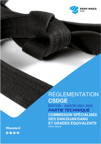
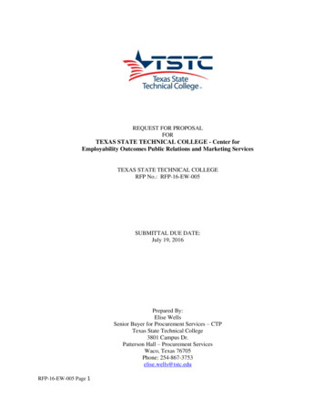
TECH NOTE—Overview of IRIG-B Time Code StandardIRIG-B PROTOCOL DESCRIPTIONTN-102 Sep-2017IRIG-B OverviewIRIG time code B (IRIG-B) is widely used in the electrical power industry. IRIG-B hasa pulse rate of 100 pulses-per-second with an index count of 10 milliseconds overits one-second time frame. It contains time-of-year and year information in a BCDformat, and (optionally) seconds-of-day in SBS.IRIG-B SignalsIRIG-B is typically distributed as a DC level shift (DCLS), pulse-width coded signal(“unmodulated IRIG-B”) or as an amplitude-modulated signal based on a sine wavecarrier with a frequency of 1kHz (“modulated IRIG-B”). Modified Manchester modulation is also specified in the standard but is less common. A comparison of IRIG-Bcoding methods is shown in the figure below.Figure 4-2.(source: IRIG Standard 200-04)IRIG B coding comparisons: level shift, 1kHz am, and Modified Manchester.IRIG-B coding comparisons: DC level shift (unmodulated), 1kHz amplitude-modulated, and Modified ManchesterIRIG-B Reference MarkersIRIG-B uses reference markers called “Position Identifiers.” The presence of two consecutive reference markers signifies the start of the time frame. The first referencemarker alerts that the next rising edge will be the PPS (Pulse-per-Second) marker.(“On-Time 1 PPS” shown above.) Thus, the IRIG-B signal provides the full date andtime once per second, as well as a precise start-of-interval reference for precise timesynchronization if needed.Figure 4-3.Modified Manchester coding. 2011-2017 Cyber Sciences, Inc. All rights reserved.www.cyber-sciences.com3
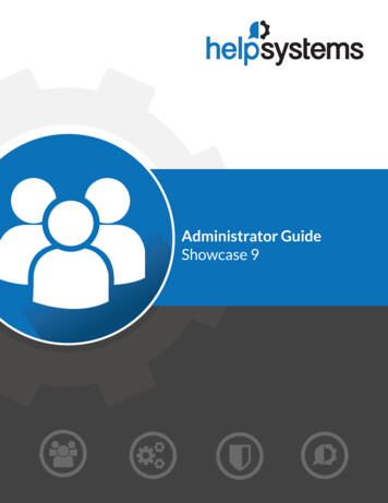
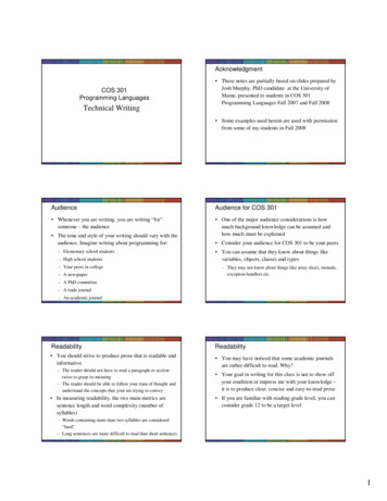
TN-102 Sep-2017IRIG-B PROTOCOL DESCRIPTION(cont.)TECH NOTE—Overview of IRIG-B Time Code StandardIRIG-B EncodingIRIG-B consists of 100 bits produced every second, 74 bits of which contain varioustime, date, time changes and time quality information of the time signal. Consisting of logic ones, zeros and position identifier bits, the time code provides a reliablemethod of transmitting time to synchronize power equipment devices. There arethree functional groups of bits in the IRIG-B time code: Binary Coded Decimal (BCD),Control Functions (CF) and Straight Binary Seconds (SBS).The BCD group contains time information including seconds, minutes, hours anddays, recycling yearly. The BCD time-of-year code (BCDTOY) reads zero (0) hours, minutes, seconds, and fraction of seconds at 2400 each day and reads day 001 at 2400of day 365, or day 366 in a leap year. The BCD year code (BCDYEAR) counts year andcycles to the next year on January 1st of each year and will count to year 2099.The (optional) SBS time-of-day code consists of the total elapsed seconds, recyclingdaily. SBS reads zero (0) seconds at 2400 each day excluding leap second days whena second may be added or subtracted.The CF group contains year, time quality, leap year, pending leap seconds and parity.Other CF bits are reserved for user-defined purposes, depending on application.Lastly, position identifiers separate the various components of the IRIG-B time code.(source: IRIG Standard 200-04)IRIG-B BCD time-of-year (in days, hours, minutes, seconds) and year and straight binary seconds-of-day and control bits4www.cyber-sciences.com 2011-2017 Cyber Sciences, Inc. All rights reserved.
TN-102 TECH NOTE—Overview of IRIG-B Time Code StandardIRIG-B PROTOCOL DESCRIPTION(cont.)Note: IEEE standard 1344 was updated and replacedby IEEE C37.118-2005. Nonetheless, the term “IEEE1344 Extensions” is still used.Sep-2017IEEE 1344 ExtensionsYear information was not specified in the IRIG standard prior to its 2004 revision. Before 2004, the IEEE adopted a standard (IEEE 1344) which included year data as partof the IRIG-B signal. This variation came to be known as “IEEE 1344 extensions.”IEEE 1344 extensions use bits of the Control Functions (CF) portion of the IRIG-B timecode. Within this portion of the time code, these bits are designated for additionalfeatures, including: Calendar Year (now called BCDYEAR) Leap seconds, and leap seconds pending Daylight Saving Time (DST), and DST pending Local time offset Time quality ParityIRIG-B Type with IEEE 1344 ExtensionsIRIG-B TYPEIEEE 1344OFFONUnmodulated, B00xB002B006Modulated, B12xB122B126IRIG-B WIRING Position identifiersTo be able to use these extra bits of information, power system devices and otherequipment receiving the time code must be able to decode them. Refer to individualproduct manuals to determine whether IEEE 1344 extensions are supported.Since year information is now considered part of BCD (denoted as BCDYEAR), whatwas formerly considered B002 and B122 (with IEEE Extensions ON) would now bedenoted as B006 and B126, respectively.IRIG-B ImplementationThe IRIG 200-04 standard does not define specific signal levels for IRIG-B.Typical techniques for transmission of unmodulated IRIG-B (DCLS) include: Point to point connection of a 5V signal over coaxial cable Multi-point distribution of a 5V signal over shielded twisted-pair cable Multi-point distribution using 24 Vdc for signal and control power Multi-point RS-485 differential signal over shielded twisted-pair cable RS-232 signal over shielded cable (point to point, short distances only) Optical fiberTypical techniques for transmission of modulated IRIG-B include: Coaxial cable, terminated in 50 ohms or higher, point-to-point Shielded twisted-pair cable, with optional termination (100 ohms)Application considerationsNote: Because the IRIG-B signal consists of a seriesof pulses, a digital scope is needed for diagnostics;a standard multi-meter is not sufficient to confirmnormal operation.When applying IRIG-B, the number and type of devices to be synchronized, the protocols supported, and the distances involved all affect system architecture; therefore,each system must be engineered individually. The first step may be to confirm thatall devices support the same version of IRIG-B, for example: unmodulated IRIG-B(also known as 5V DC Level Shift, or DCLS), with or without the year (IEEE 1344extensions), etc. The IRIG-B signal is wired to a general-purpose or dedicated digitalinput, configured to decode IRIG-B.The IRIG-B source (e.g., GPS receiver/clock) may be capable of synchronizing a smallnumber of devices in series (up to 8 or 10?) but a larger number of devices mayrequire multiple circuits, repeaters and/or isolation means. Careful consideration isneeded of clock specs, cable distances and device limitations. In some cases, it maybe necessary to add appropriate termination impedance to each IRIG-B signal toeliminate signal reflections. 2011-2017 Cyber Sciences, Inc. All rights reserved.www.cyber-sciences.com5
TN-102 Sep-2017TECH NOTE—Overview of IRIG-B Time Code StandardAPPLICATIONS OF IRIG-B INCYBER SCIENCES PRODUCTSCyTime SER-3200-PTP (or SER-2408-PTP)SER-3200/2408 Time Source Options(Time-Sync IN)Time source options via PTP, NTP or Modbus TCP use the SER-3200/2408 built-inEthernet interface (RJ-45). IRIG-B or DCF77 inputs require an adapter (EZC-IRIG-B orEZC-DCF77) as shown.CyTime SER-3200/2408 Event Recorders accept IRIG-B as time source, then sync witheach other using PTP. A PTP slave can also output IRIG-B to devices that do not support PTP. Other time-sync input and output options are also supported for flexibilityand interoperability with other devices.DCF77IRIG-BPTP or NTP orModbus TCP(over TP(or SER-2408-PTP)SER-3200/2408-PTP as Time-sync Hub(Time-Sync OUT)When PTP is selected as time source, the SER-3200/2408 also serves as a “PTP timesync hub” for non-PTP devices, generating the time-sync protocol needed: IRIG-B,DCF77, 1per10 (via PLX adapter) or ASCII (via built-in RS-485 port), as shown below.IRIG-B (5V DCLS)Note: Only one protocol can be selected for outputvia the PLX connector (IRIG-B, DCF77 or 1per10).However, for maximum flexibility, the ASCII / RS-485output is enabled by default any time an SER is set touse PTP for time source (IN) or time-sync r SER-2408-PTP)6www.cyber-sciences.comIRIG-B (24V, to STR-IDM)DCF77 (24V)1per10 (24V)ASCII (RS-485) 2011-2017 Cyber Sciences, Inc. All rights reserved.
TN-102 TECH NOTE—Overview of IRIG-B Time Code StandardAPPLICATIONS OF IRIG-B INCYBER SCIENCES PRODUCTS (cont.)If Modulated IRIG-B input is used, the STR-100 mustbe configured with the current year during initialsetup. The full date/time (including the year) istransmitted via its DCF77 outputs.STR-100 Satellite Time ReferenceThe Cyber Sciences STR-100 Satellite Time Reference accepts a GPS smart antennainput or a modulated IRIG-B signal to provide a precision time reference. The IRIG-Binput supports type B122 (1kHz modulated signal with time of year).Acutime 360GPS Antenna InputBNC-to-screwterminal adapter24 Vdccontrol powerCH 2DCF77 Output(or 1per10)STR-100Satellite Time ReferenceDCF77 Output}(optional)24V levelsSTR-100/IRIG-BLike the base model, the STR-100/IRIG-B accepts a GPS smart antenna input, but itsoutput is an unmodulated IRIG-B signal, type B006 (unmodulated signal, DC levelshift, BCDTOY and BCDYEAR) at 5V (side BNC) or 24V (front terminals).NOTE: The STR-100/IRIG-B (IRIG-B output modelonly) is pending obsolescence, effective April 2016.Available by special order or limited to quantitieson hand. For new installations, Cyber Sciencesrecommends using an SER-3200-PTP with PLX-5Vor PLX-24V option. (See next page for details.)Acutime 360GPS Antenna Input(optional)BNC-to-screwterminal adapter24 Vdccontrol powerUnmodulatedIRIG-B Output(5V levels)STR-100/IRIG-BSatellite Time ReferenceSTR-IDMIRIG-B Distribution ModuleModulatedIRIG-B InputORCH 1STR-100/IRIG-B (IRIG-B out)Satellite Time ReferenceSep-2017IRIG-B @ 24V levels, plus24 Vdc control power(to STR-IDM)STR-IDMThe STR-IDM IRIG-B Distribution Module enables the distribution of an unmodulatedIRIG-B signal over long distances and to multiple devices. The IRIG-B signal levelsbetween the PLX-24V (or STR-100/IRIG-B) and the first IDM (as well as to other IDMs)are 24 Vdc nominal, along with 24 Vdc control power. Each STR-IDM provides 8 additional IRIG-B outputs, type B006 (unmodulated signal, 5V DC level shift, BCDTOYand BCDYEAR).24V IRIG-B plus 24 Vdc power(from PLX-24V orSTR-100/IRIG-B24V IRIG-B plus 24 Vdc power(to next STR-IDM)STR-IDMIRIG-B Distribution ModuleUnmodulated IRIG-BOutputs (x8)(5V levels) 2011-2017 Cyber Sciences, Inc. All rights reserved.www.cyber-sciences.com7
TN-102 Sep-2017TECH NOTE—Overview of IRIG-B Time Code StandardPRECISION TIME PROTOCOL (PTP)per IEEE 1588Time Synchronization as Easy as 1-2-3PTP (Precision Time Protocol defined in IEEE 1588) takes advantage of hardwareassisted timestamping to achieve sub-millisecond time synchronization over an Ethernet network. Cyber Sciences offers simple, scalable system architectures using PTPas the means to distribute a precise time reference to all devices that support PTP.CyTimeTM SER-3200/2408-PTP Event Recorders accept a variety of time-source options, and sync with each other automatically over Ethernet, using PTP. In addition,an SER can serve as a “PTP time sync hub” for devices that do not yet support PTP.For More Info on PTP:Tech Note: Hi-res Time Sync using PTP/1588 (TN-100)Simple, building-block options are shown below. The first CyTime SER accepts a timereference signal (such as IRIG-B), then serves as PTP master clock for all other SERsas well as other devices which support PTP. For a device that does not support PTP, anearby SER outputs the protocol needed (e.g., IRIG-B) effectively making this device“PTP-enabled” as SclockEthernetNTPTIMESOURCESER-3200-PTPEthernet(up to 200 PTP slaves)SER-3200-PTP(or SER-2408-PTP)(or SER-2408-PTP)EPMSdevice(or SER-2408-PTP)SER-3200-PTPSER-3200-PTP(or SER-2408-PTP)SER-3200-PTP(or SER-2408-PTP)PTPEPMSdeviceSER-3200-PTP(or SER-2408-PTP)PTP(up to 200 PTP slaves)(up to 200 PTP EPMSserverSER-3200-PTPPTPSLAVES(or SER-2408-PTP)SER-3200-PTP(or SER-2408-PTP)SER-3200-PTP(or SER-2408-PTP)IRIG-B orDCF77 or1per10 orASCIIEPMSdeviceChoose a Time SourceSync all SERs with Each Other (PTP)Sync Other EPMS DevicesSet the first SER’s time from a web browser,EPMS software or NTP server. Optionally, adda GPS antenna/receiver to provide an externaltime reference traceable to UTC (CoordinatedUniversal Time), to compare data from othersites or organizations (e.g., electric utilities).Configure the first SER to output PTP (PTPgrandmaster clock); all other SERs on thesame Ethernet network sync with each otherautomatically (within 100 µsec). No specialEthernet switches. No additional setup.Simple, affordable, scalable.Sync SERs with other EPMS devices using PTPover Ethernet, all within 100 µsec. No PTP? Noproblem! For devices that do not yet supportPTP, a CyTime SER (PTP slave) can serve as a“time-sync hub” to output the legacy protocolneeded (IRIG-B, DCF77, ASCII, or 1per10).8www.cyber-sciences.com 2011-2017 Cyber Sciences, Inc. All rights reserved.
TN-102 TECH NOTE—Overview of IRIG-B Time Code StandardSYNCHRONIZING NON-PTP DEVICES(via IRIG-B)Time-sync Output: Unmodulated IRIG-B ( 8 devices)A CyTime SER (with PTP enabled) can be configured to output the most commonform of IRIG-B: unmodulated, or DC Level Shift (DCLS) at 5 Vdc nominal. A PTP Legacy Interface (PLX-5V) connected to the SER DB-15 port outputs the signal at 5 Vdcnominal. This IRIG-B time code supports the full date/time, including the year (IRIGcode “B006”), and is compatible with most meters and relays that support IRIG-B.Daisy-chain wiring, Belden 8760 cable orequivalent, 1000 ft (300m) max total length.Ethernet LANPTPPLX-5VIRIG-BIRIG-B termination (if needed)PTP SLAVE(Time source PTP)(Time-sync out IRIG-B)MENUENTERSep-2017.IRIG-BDevices that support IRIG-B include:IRIG-B—Most overcurrent protective relays—PM8000 meters (Schneider Electric)—9410 meters (Siemens)up to 7devicesSER-3200-PTP(or SER-2408-PTP)Time-sync Output: Unmodulated IRIG-B (8 or more devices)For reliable distribution over longer distances or to a greater number of devices, thissame IRIG-B code can be output at 24 Vdc using a PLX-24V accessory instead. Thissignal is then distributed (with 24 Vdc control power) via a multi-point connectionto “IRIG-B Distribution Modules” (IDM) which in turn convert the signal back to theexpected 5 Vdc for point-to-point connection to up to eight (8) IRIG-B devices.Daisy-chain wiring, Belden 8770 cable orequivalent, 2000 ft (600m) max total length.IRIG-B (24V DCLS) 24Vdc powerSTR-IDMSTR-IDMEthernet LANPTPPLX-24VMENUENTERSTR-IDMSTR-IDMIRIG-B (5V DCLS)PTP SLAVE(Time source PTP)(Time-sync out IRIG-B)To next STR-IDM (4 total)1 to 4 STR-IDMmodules per PLXIRIG-BSER-3200-PTP.up to 8devicesIRIG-BIRIG-B (5V DCLS)IRIG-B.up to 8devicesIRIG-B(or SER-2408-PTP) 2011-2017 Cyber Sciences, Inc. All rights reserved.www.cyber-sciences.com9
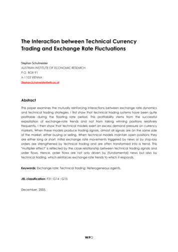
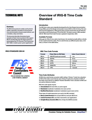
TN-102 Sep-2017TECH NOTE—Overview of IRIG-B Time Code StandardEPMS SYSTEM EXAMPLE(Sync 2 or more SERs via IRIG-B:PTP Master and PTP Standby Master)An EPMS (Electrical Power Management System) example is shown below that usesPTP for time synchronization over Ethernet, with IRIG-B from the time source (GPSclock) and SERs as PTP time-sync hubs to output IRIG-B to devices that do not support PTP directly.Time Source. In addition to the first SER, a second CyTime SER accepts IRIG-B as itstime source from the GPS clock. In this design, both SERs are configured as a PTPmaster using the same PTP domain number. Using the IEEE 1588 “Best Master Clock”algorithm, one SER automatically acts as the PTP grandmaster clock, and the otherwaits in standby mode in case it is ever needed as a backup.Time Distribution. The first SER (or the backup SER) serves as PTP grandmaster forall other CyTime SERs (PTP slaves), synchronized within 100 µsec of each other. Ifthe first clock fails or goes offline, the backup PTP master becomes the grandmasterclock automatically and remains in service until the other is restored. This ensuresreliable, uninterrupted time service to all devices.Time Conversion. The devices located in other power distribution equipment enclosures are synchronized from a nearby SER, using the protocol needed (e.g., IRIG-B). IRIG-B (5V DCLS)GPSAntennaEPMSSOFTWARE DCF77 (24V DCLS)WEBBROWSER 1per10 (24V DCLS) ASCII / (or 0-PTP(or SER-2408-PTP)PTPSlaveRelay(or SER-2408-PTP)(or SER-2408-PTP)MeterMeterMeterSER-3200-PTP(or SER-2408-PTP)ASCII / RS-485ASCII / RS-485MV SWGRGEN rSER-3200-PTPPTPSlavePLX-24VMeterSER-3200-PTP(or SER-2408-PTP)PTPSlaveMeterSER-3200-PTP(or SER-2408-PTP)PDP 1IRIG-BPTPSlaveSER-3200-PTP(or SER-2408-PTP)MeterPTPSlaveSER-3200-PTP(or SER-2408-PTP)LV SWBD nPLX-24VMeterASCII / RS-485DCF77PLX-5VMeterUPS 1IRIG-BPLX-5VMeterSER-3200-PTP(or SER-2408-PTP)(or SER-2408-PTP)LV SWBD 1PTPSlavePTPSlaveSER-3200-PTP(or SER-2408-PTP)PDP nMeterPTPSlaveMeterSER-3200-PTP(or SER-2408-PTP)UPS nASCII / RS-485EPMS SYSTEM EXAMPLE—High-def time-sync over Ethernet using PTP; two SERs accept IRIG-B from GPS clock, one is PTP master, other is standby10www.cyber-sciences.com 2011-2017 Cyber Sciences, Inc. All rights reserved.
TECH NOTE—Overview of IRIG-B Time Code StandardREFERENCESTN-102 Sep-2017References[1] IRIG Standard 200-04: “IRIG Serial Time Code Formats.” September, 2004. RangeCommanders Council, U.S. Army White Sands Missile Range, New Mexico 880025110.[2] IEEE C37.118-2005 (replaced IEEE Standard 1344). IEEE Standard for Synchrophasors for Power Systems. Institute of Electrical and Electronics Engineers (IEEE).January 1, 2006.[3] Kennedy, Robert A., P.E., “GPS Time Synchronization: How precision timing andsequence of events recording will make the Smart Grid even smarter,” Electrical Construction & Maintenance (EC&M) magazine, August 19, 2011, pp. -time-synchronization[4] Brown, PE, Bill, and Mark Kozlowski, “Power System Event Reconstruction Technologies for Modern Data Centers,” Square D Critical Power Competency Center. Aug. 2006.[5] Dickerson, Bill, P.Eng., Arbiter Systems, Inc. “Time in the Power Industry: How andWhy We Use It.”[6] Dickerson, Bill, P.Eng., Arbiter Systems, Inc. “IRIG-B Time Code Accuracy and Connection Requirements with comments on IED and system design considerations.”Publication PD0037300. 2011-2017 Cyber Sciences, Inc. All rights reserved.www.cyber-sciences.com11
TN-102 Sep-2017TECH NOTE—Overview of IRIG-B Time Code StandardFor More InformationEPMS-HD Data Sheet (DS-PTP-01)Tech Note: Hi-res Time Sync using PTP/1588 (TN-100)Tech Note: SER System Design Guide (TN-101)Tech Note: DCF77 Time Protocol (TN-103)Tech Note: 1per10 Time Protocol (TN-104)Tech Note: ASCII/RS-485 (TN-108)CyTime SER User’s Guide (IB-SER-01)CyTime SER Reference Guide (IB-SER-02)EZC Instruction Bulletin (IB-EZC-01)PLX Instruction Bulletin (IB-PLX-01)STR-100 Instruction Bulletin (IB-STR-01)STR-IDM Instruction Bulletin (IB-IDM-01)The service marks, “Precision Timing for Reliable Power. Simplified.” and “I-Heart-1588”,CyTime, and the Cyber Sciences stylized logo are trademarks of Cyber Sciences.All other trademarks are the property of their respective owners.MADE IN USACyber Sciences, Inc. (CSI)229 Castlewood Drive, Suite EMurfreesboro, TN 37129 USATel: 1 615-890-6709Fax: 1 eI1588SMDoc. no: TN-102 Sep-2017(supersedes doc. dated May-2016) 2011-2017 Cyber Sciences, Inc. All rights reserved.
200-04, "IRIG Serial Time Code Formats," updated in September, 2004. Available Formats Although the "IRIG-B" time code is best known, the standard actually defines a family of rate-scaled serial time codes. The six code formats use different pulse rates, or bit rates, as shown in the table below. IRIG Time Code Formats