Transcription
MECA0063: Vehicle ArchitectureSuspension technologiesPierre DuysinxResearch Center in Sustainable AutomotiveTechnologies of University of LiegeAcademic Year 2020-20211
References R. Bosch. « Automotive Handbook ». 5th edition. 2002. Societyof Automotive Engineers (SAE)G. Genta & L. Morello. The automotive chassis. Vol 1Components Design. Springer. 2009.T. Gillespie. « Fundamentals of vehicle Dynamics », 1992,Society of Automotive Engineers (SAE)T. Halconruy. Les liaisons au sol. ETAI. 1995.H. Mémeteau. « Technologie Fonctionnelle de l’Automobile ».4ème édition. Dunod. Paris. 2002.W. Milliken & D. Milliken. « Race Car Vehicle Dynamics », 1995,Society of Automotive Engineers (SAE)J. Reimpell, H. Stoll, J. Betzler. « The automotive chassis:engineering principles ». 2nd edition. 2001, SAE.2
References: web resources Autozine:https://www.autozine.org/technical school/handling/tech handling 2.htm3
Outline RIGID AXLES SUSPENSIONS General considerationsHotchkissFour linkDe DionSEMI RIGID SUSPENSIONS4
Outline INDEPENDENT SUSPENSION Trailing arm suspensionShort Long Arms: A arms H armMc PhersonFive linksRear trailing arm suspensionSemi trailing arm suspensionSwing axle5
Lesson 2:CONSTRUCTIVE TECHNOLOGY OFSUSPENSIONS6
Solid axles7
Solid axles8
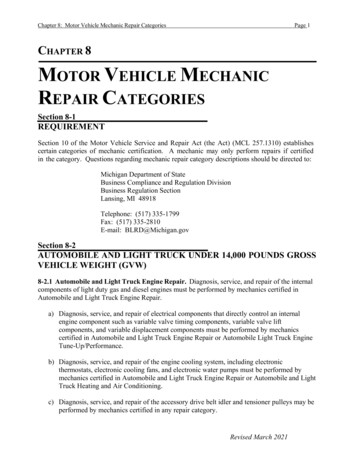
Solid axles On solid axles, the two wheels are mounted at the two ends ofa rigid shaftThe motion of one wheel is transmitted to the other oneBoth wheels experience common camber and steering motionsThe solid axles are used on live (motorized) axles: On rear axles of many trucks and on some passenger cars (e.g.pick-up vehicles)On front axles of four-wheel drive trucksSolid axles are also used On front axles of trucks when large-load capacity is required9
Solid axles10
Solid axles Advantages of solid axles: The camber of the wheels is not affected by the body roll, theunevenness of the roadNo wheel camber angles in turn, except the higher compression ofthe outer tires due to lateral load transferThe alignment and the wheel track are preserved minimizing wearDisadvantages of solid axles Major drawback is the susceptibility to vibrations, tramp-shimmy ofsteeringSuspended mass is high, so higher transmissibility of vibrationsfrom road to rolling body11
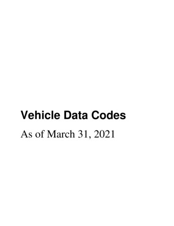
Solid axles: HotchkissGillespie Fig7.1: Hotchkiss suspension12
Solid axleToyota Tacoma rear solid axle13
Solid axles: Hotchkiss The most common and the oldest type of solid axlesThe axle is centered and damped with semi-elliptic leaf springsTransmission of engine power through a longitudinal shaft withtwo universal joints (Hook-Cardan) (constant velocity lay-out)The leaf springs are mounted longitudinally and are connectedto the body at the two ends (one fixed end and one free endnot to constrain its extension)The leaf spring also ensures other functions like lateral guidanceof the axles and also the transmission of longitudinal forcesdeveloped in the tire-ground contact patch.14
Solid axles: Hotchkiss The roll of a Hotchkiss withleaf springsMilliken Fig 17.4415
Solid axles: HotchkissHeisler Fig 7.7 Leaf spring micro bending due to acceleration/braking torques16
Solid axles: HotchkissADVANTAGES ( ) Low manufacturing costDRAWBACKS (-) Important unsprung mass (-) Uncontrolled friction between the leaf springs (-) Suspension travel due to lateral forces (-) Loss of stability with softer (i.e. longer) springs for light cars. (-) Lateral deformation and torsion appears when passing hightorque and high engine power. Thus reintroduction of tractionarms and lateral guidance bars to sustain high braking / tractionforces17
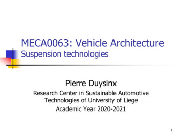
Solid axles: 4 linksGillespie Fig 7.2: Four link suspension18
Solid axles: 4 links19
Solid axles: 4 links Answer to the difficulties of leafspringsGood choice for large passengercars with rear solid axleThe lower control arms transfer thelongitudinal forces and provide thelongitudinal controlThe upper arms take the braking /traction torques and the lateralforcesThe set of upper arms can bereplaced by a triangular arm, butwith a similar functionality20
Solid axles: 4 linksADVANTAGES - DRAWBACKS ( ) Enables to use coil springs or air springs to increase thecomfort, reduce the uncontrolled friction, increase NVH comfort (-) More expensive ( ) Better control of the roll center of the suspensionmechanism ( ) It makes possible to tailor anti-dive and anti squatgeometries ( ) Better properties for the roll stiffness and roll-steerproperties21
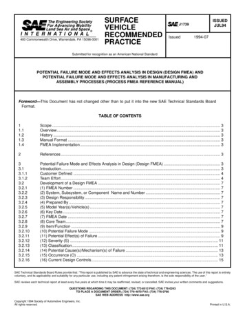
Solid axles: de DionGillespie Fig 7.3 : De Dion Suspension22
Solid axles: de DionMilliken Fig 17.43 : de Dion suspension23
Solid axles: de Dion Across between solid axles and independent suspensions, theDe Dion axle (patented by the Count de Dion and GeorgesBouton in 1894) consists of a cross tube between the twodriving wheels and of two half shafts connected to thedifferential.The differential is mounted on the chassis to reduce theunsprung mass.The tube is curved to avoid geometrical interference with thedifferential24
Solid axles: de Dion The system is classic, but of little use in practiceThe tube maintains a perfect geometry of the wheelsThe tube is sometimes able to extend by sliding to have a bettercomfortThe control of the lateral motion requires a sliding tube or asplined shafts, which add friction into the systemThe motion of the axle can be controlled by various spring anddamping systems25
Solid axles: de DionADVANTAGES - DRAWBACKS ( ) Like solid axles, the system maintains the wheels in aproper geometry, while reducing the unsprung mass ( ) The control of the de Dion Axles can be achieved either byleaf springs or by coil (air) springs (-) The sliding pivot introduces some friction in the system ( /-) One has to introduce a lateral guidance system (e.g. aPanhard bar) ( /-) Better comfort than solid axles (lower unsprung mass),but still remain below what can be offered by independentsuspensions systems.26
Solid axles: de DionExamples: Smart Fortwo, Alfa GTV6, Mazda Cosmo 27
Solid axles: de DionDe Dion axle of Alpha Romeo GTV628
Lateral restriction systemsMilliken Fig. 17.16 : System for restraining the lateral motion29
Semi-rigid axles30
Semi-rigid or twist axle rear suspensionsSemi rigid suspension of VW Golf31
Semi rigid suspension Quite novel family of suspension systemsMostly used for the rear axle of small (A/B) passenger cars withfront driveOrigin of the name: a beam axle experiences some torsion toenable the roll motion of the unsprung massThe axle kinematic allows controlling all parameters except theanti squat because there is no applied traction torqueThree major types (lay-out) of semi rigid axles depending onthe position of the twisting beamThe roll axis is modified by the position of the twist beam32
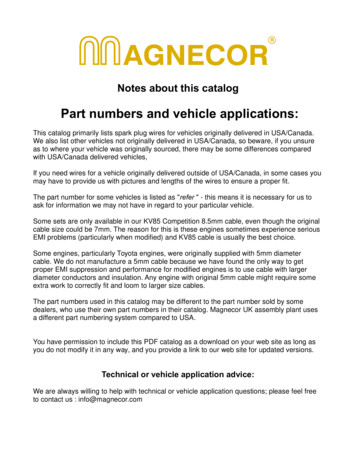
Semi rigid suspensionNb 2Nj 3M 2*6-2*3-1*4 2Working principle of a semi rigid suspension33
Semi rigid suspension This is the simplest type of axles. Using a very schematicanalysis, it can be modeled as longitudinal arms hinged to thechassis, connected by a torsion spring, and completed byvertical coil springs, and shock absorbersIn some cases, the coil springs can be substituted by torsionbarsThis type of suspension is very compact, easy to manufacture,simple to assembleThe semi rigid axle lay out does not allow to transmit someengine torque so that it can only be implemented on the rearaxle of front wheel driven cars34
Semi rigid suspension Type a: twist beam is located atthe level of the bearing with thechassis.Similar to an independent trailingarm suspensionType b: The twist beam ispositioned at mid way between thebearings and of the wheels.In rebound, there is a rotationabout the axis of the bearingsIn roll, it has the same propertiesas a semi-trailing arm independentsuspensionsType c: The twist beam is locatedin the axis of the wheelsRequires a Panhard bar to restrainthe lateral motion35
Semi rigid suspensionADVANTAGES – DISADVANTAGES ( ) The large distance between the supports (bearings)minimizes the structural stresses in the car body ( ) Load transfer is favorable to longitudinal arms ( ) Simple to manufacture ( ) Attachment by two points only Simple to assemble ( ) Extremely robust (-) Rather limited kinematic capabilities (limited geometricparameters)36
Semi rigid suspension Semi rigid axles are used on many mid class passenger cars(segment C: VW- Golf, Fiat Punto )37
Independent suspension38
Independent suspensions Contrary to solid axle suspensions, the independent suspensionallows an independent motion of the two wheels of the axle.The vertical motion of one wheel does not affect the motion andthe geometry of the other oneNearly all modern cars and light duty vehicles have independentsuspension systems on the front wheelsThe major advantages of independent suspensions are: They are very compact and allow for a larger space for the enginecompartmentThey improve the comfortThey improve the handling39
Independent suspensionsADVANTAGES They are very compact and allow for a larger space for theengine compartment, which enables a lateral engine mounting Provide a better resistance to shimmy and wobble vibrations bydecoupling the wheels and interposing the mass of the engine Provide a higher roll stiffness with a given vertical spring rate Easy control of the roll center by controlling the position and thegeometry of the suspension arms Capability of controlling i.e. minimizing the modification of thewheel geometry and so the pressure distribution in the contactpatch in bounce and rebound Larger suspension travel than solid axles40
Independent suspension with trailing arms Historical success of VW andPorsche cars during WWIIFront parallel trailing armswith the same dimensions,connected on their front partto a torsion bar that providesthe spring systemThe wheels remain parallel,but they take the samecamber as the roll of theunsprung massGillespie Fig. 7.4Independent suspension withtrailing arms41
Independent suspension with trailing arms42
Short Long Arm (SLA) Front SuspensionGillespie Fig 7.5 A arm suspension43
Short Long Arm (SLA) Front Suspension The most common lay out in many passenger carsafter WWIITwo triangular arms maintain the geometry of thewheelsThe upper and lower arms have generally differentlengths so the name of short long arm suspensionThe arms are generally named A-arm or H-arm(USA), wishbones (GB), suspension triangles (enfrançais)Variants or equivalent designs: The upper arms is replaced by a simple unique linkThe lower arms is substituted by a lateral arm and anangle strut44
Short Long Arm (SLA) Front Suspension The SLA suspensions are welladapted to Vehicles with a longitudinal engineat the front and rear drive wheelVehicles with a chassis subframeseparated for the benefit of theassembly and for shock absorption45
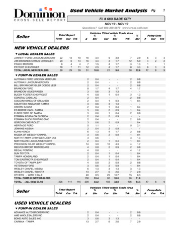
Short Long Arm (SLA) Front SuspensionHeisler Fig 7.34 : Effect of short long arms on the minimization of the wheel trackchange46
Short Long Arm (SLA) Front SuspensionNo camber changeEqual camber changeSmaller camber change on outer wheelCamber modification of A-arms on modification of camber change: (left) equallength vs (right) short-long arms47
Short Long Arm (SLA) Front SuspensionSmaller camber change on outer wheelReduction of camber modificationCamber modification of A-arms on modification of camber change : (left)parallel vs (right) non-parallel48
Short Long Arm (SLA) Front Suspension5 7 9 The design of the geometry calls forgreat care to reach high performancesThe geometry of the arms (hingeposition) can improve the camber ofthe outer wheel by counteracting thewheel camber due to roll at the price ofa higher camber on the inner wheelTaking unequal arms is attenuating theunfavorable conditions on the outerwheel, even though deteriorating thecompensation on the inner wheelIt is necessary to minimize the contactpatch modifications during wheel travel49
Short Long Arm (SLA) SuspensionDouble triangle suspensions mounted on a chassis subframe50
Short Long Arm (SLA) Suspension Porsche 993 (rear rollingtrain)51
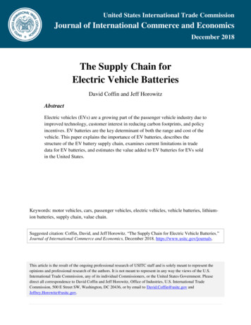
Mac Pherson suspensionGillespie Fig. 7.6 Mc Pherson strut suspension52
Mac Pherson suspension Mc Pherson developed a suspension geometrysimilar to SLA suspension using a telescopic strutThe strut is a prismatic joint combined with a shockabsorberThe wheel is rigidly attached on the lower end ofthe strut, so the prismatic joint maintains the wheelin a predefined camber geometryThe lower part of the strut takes is subject to thelateral and longitudinal forces generated in thewheel contact patch because of the rigidconnections with the wheel knuckleIn its upper part, the strut is connected to the carbody using a spherical joint53
Mac Pherson suspensionExamples: Fiat Croma, LanciaThema, Saab 9000, Fiat Tipo,Tempra, Lancia Delta, Dedra 54
Mac Pherson suspension The Mc Pherson structcombines :A sliding tube,A damping element,A spring element.55
Mac Pherson suspensionGenuine Mc Pherson system System combining the damper,the spring element and theknuckle.The system includes also thewheel carrier.The stabilizing bar is used forguidance.The combined shock absorber isbounded in the lower part tothe wheel carrier and the upperpart directly to the car body.56
Pseudo Mac Pherson suspension The hub (5) is bounded to the Mc Phersoncombined strut and shock absorberThe lower link (2) is a triangular arm ableto take over the longitudinal forcesWith only the lower triangle, it is notpossible to control the dynamic camber.However, the strong lower arm enables topass large torque and power.It is generally used for mid size cars andvery often on front wheels of front wheeldriven vehicles.57
Mac Pherson suspensionADVANTAGES - DRAWBACKS ( ) The Mac Pherson system is extremely compact. It allowsthe lateral engine mo
Solid axles On solid axles, the two wheels are mounted at the two ends of a rigid shaft The motion of one wheel is transmitted to the other one Both wheels experience common camber and steering motions The solid axles are used on live (motorized) axles: On rear axles of many trucks and on some passenger cars (e.g. pick-up vehicles) On front axles of four-wheel drive trucks