Transcription
Chapter 2:Radio Wave Propagation FundamentalsM.Sc. Sevda AbadpourDr.-Ing. Marwan YounisINSTITUTE OF RADIO FREQUENCY ENGINEERING AND ELECTRONICSKIT – The Research University in the Helmholtz Associationwww.ihe.kit.edu
Scope of the (Today‘s) LectureEffects during wireless transmission of signals: physical phenomena that influence the propagationof electromagnetic wavesDAanalogsource &channeldecoding no statistical description of those effects in termsdigitaldemodulationof modulated pter 2: Radio Wave Propagation FundamentalsTime and FrequencySelective Radio ChannelInstitute of Radio Frequency Engineeringand Electronics
Propagation PhenomenarefractionzTreflectionzRpath Ndiffractiontransmitter QTiyTxTyTiQRi receiverpath ixRyRipath 1yRscatteringfree spacepropagation:- line of sight- no multipathreflection:- plane wave reflectionscattering:- Fresnel coefficients- volume scatteringdiffraction:- knife edge diffraction- rough surface scatteringrefraction in thetroposphere:- not consideredIn general multipath propagation leads to fading at the receiver site312.11.2018Chapter 2: Radio Wave Propagation FundamentalsInstitute of Radio Frequency Engineeringand Electronics
The Received SignalSignal fadingattenuation that a signal experiencesover certain propagation media.It may vary with time, positionFrequencyFading is a deviation of theand/or frequencyTimeClassification of fading: large-scale fading (gradual changein local average of signal level) small-scale fading (rapid variationslarge-scale fadingsmall-scale fading412.11.2018Chapter 2: Radio Wave Propagation Fundamentalsdue to random multipath signals)Institute of Radio Frequency Engineeringand Electronics
Propagation ModelsPropagation models (PM) are being used to predict: average signal strength at a given distance from the transmitter variability of the signal strength in close spatial proximity to a particular locationPM can be divided into:Severe multipath conditions inurban areas (small-scale fading) large-scale models(mean signal strength for largetransmitter receiver separation) small-scale models(rapid fluctuations of the receivedsignal over very short travel distances)512.11.2018Chapter 2: Radio Wave Propagation FundamentalsInstitute of Radio Frequency Engineeringand Electronics
Large-Scale PropagationFree Space Propagation612.11.2018Chapter 2: Radio Wave Propagation FundamentalsInstitute of Radio Frequency Engineeringand Electronics
Free Space PropagationTxRxPtPrGtGrAssumptions: unobstructed line of sight (LOS) no multipath propagationrno (influence of) groundReceived power:Power density at Rx site:Antenna effective area:Friis free space equation:712.11.2018Chapter 2: Radio Wave Propagation FundamentalsInstitute of Radio Frequency Engineeringand Electronics
Received Power and Path LossUsing:iiAssumptions: polarization matched receiving antenna conjugate complex impedance matching of the receiverPath loss:Isotropic path loss (no antenna gains):812.11.2018Chapter 2: Radio Wave Propagation FundamentalsInstitute of Radio Frequency Engineeringand Electronics
PolarizationOrientation of Field Vectors and Reference Planes912.11.2018Chapter 2: Radio Wave Propagation FundamentalsInstitute of Radio Frequency Engineeringand Electronics
Polarization of the EM WavesEvery elliptically polarized EM wave can be decomposedinto a horizontal and a vertical ter 2: Radio Wave Propagation FundamentalsInstitute of Radio Frequency Engineeringand Electronics
TPolarization: II, , V or H?Plane of incidence: formed by thenormal vector to the reflecting surfaceand Poynting vector of the incidence waveEII or EVE or EHTPolarization (E-field vector) withPolarization (E-field vector) withrespect to the plane of incidence:respect to the earth coordinates: parallel (II) vertical (V)T perpendicular ( )1112.11.2018Chapter 2: Radio Wave Propagation Fundamentals horizontal (H)Institute of Radio Frequency Engineeringand Electronics
Reflection andTransmissionDielectric Boundary1212.11.2018Chapter 2: Radio Wave Propagation FundamentalsInstitute of Radio Frequency Engineeringand Electronics
Snell’s Law of Reflectionθ i θr surface large compared to the wave length1 smooth surface (otherwise scattering) three angles:2- incidence- reflection- transmission / refractionθt Relation between angles through Fermat’s principle (principle of least time):- “the rays of light (EM-waves) traverse the path of stationary optical length” This results in* Snell’s laws:- “ratio of the sines of the angles of incidence and refraction isequivalent to the opposite ratio of the indices of refraction”- “the incidence and reflection angles are equal and they are in the same plane”sin( i ) n2 sin( t ) n1nx r , x r , x i r*full derivation in Arthur Schuster: “An Introduction to the Theory of Optics”1312.11.2018Chapter 2: Radio Wave Propagation FundamentalsInstitute of Radio Frequency Engineeringand Electronics
Which Part is Transmitted / Reflected?Derivation procedure: Definition of the electric field strength of the incident wave Reflected and transmitted field strengths Faraday’s law of induction Boundary conditions at the border between two dielectric media Decomposition of the incident waves on parallel and normal components1412.11.2018Chapter 2: Radio Wave Propagation FundamentalsInstitute of Radio Frequency Engineeringand Electronics
Fresnel Reflection & Transmission Coefficientsparallelperpendicularwhere:Fresnel coefficients are frequencydependent and in general complex1512.11.2018Chapter 2: Radio Wave Propagation FundamentalsInstitute of Radio Frequency Engineeringand Electronics
Brewster‘s Angle (I)Angle, where no reflection occurs is Brewster’s Angle: exists only for parallel (II / V) polarization calculation by comparing the reflection coefficient to zero calculation by using “physical limitations”1612.11.2018Chapter 2: Radio Wave Propagation FundamentalsInstitute of Radio Frequency Engineeringand Electronics
Brewster‘s Angle (II)Air (less dense)Glass (dense)1712.11.2018Chapter 2: Radio Wave Propagation FundamentalsInstitute of Radio Frequency Engineeringand Electronics
phase in degreeBrewster‘s Angle (III)1812.11.2018Chapter 2: Radio Wave Propagation FundamentalsInstitute of Radio Frequency Engineeringand Electronics
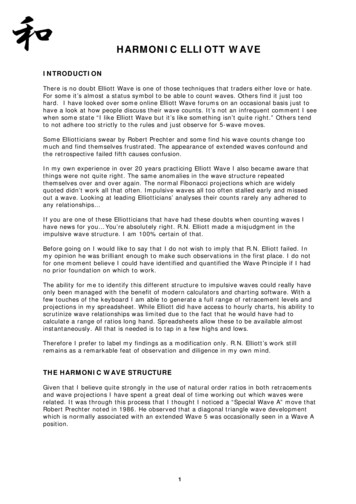
Brewster‘s Angle (IV)Operation principle of Brewster window: used for windows in optical or quasi optical systems window with normal incidence reflection loses at window window tilted at Brewster’s angle no reflection loses at windowMicrowave gyrotron1912.11.2018Chapter 2: Radio Wave Propagation FundamentalsBrewster windowInstitute of Radio Frequency Engineeringand Electronics
Total Internal Reflection (I)When does the total internal reflection appears? a ray must strike the medium’s boundaryat an angle larger than the critical angle calculation by comparing then sin n sin iit n arcsin ntcitransmission angle to 90 degreeIncreasing the incidence angle2012.11.2018Chapter 2: Radio Wave Propagation Fundamentalst t 90 critical angle exists only for nt niTotal reflection of red laser light in PMMAInstitute of Radio Frequency Engineeringand Electronics
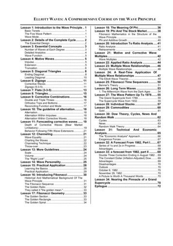
Total Internal Reflection (II)Operation principle of rain sensors: IR-beam projected on the glass-air interface at a specific angle total inner reflection in dry conditions partial transmission to the second medium if windshield is wet reduced receive power triggers the sensorRain sensor in the rear view mirror2112.11.2018Chapter 2: Radio Wave Propagation FundamentalsInstitute of Radio Frequency Engineeringand Electronics
Visualization Parallel Pol – E-FieldParallel Pol – Air to Glass2212.11.2018Chapter 2: Radio Wave Propagation FundamentalsParallel Pol – Glass to AirInstitute of Radio Frequency Engineeringand Electronics
Visualization Perpendicular Pol – E-FieldPerpendicular Pol – Air to Glass2312.11.2018Chapter 2: Radio Wave Propagation FundamentalsPerpendicular Pol – Glass to AirInstitute of Radio Frequency Engineeringand Electronics
Reflection and(no) TransmissionPerfect Electric Conductor (PEC)2412.11.2018Chapter 2: Radio Wave Propagation FundamentalsInstitute of Radio Frequency Engineeringand Electronics
Orthogonal PEC ReflectionBoundary conditions: Etan Etan, i Etan, r 0 H norm H norm ,i H norm,r 0reflected waveincident r 2: Radio Wave Propagation FundamentalsInstitute of Radio Frequency Engineeringand Electronics
PEC Reflection, Orthogonal ne of incidenceEyiaiEyHziHzrHEyrPEC reflectorPEC reflection:HxrHr RII 1x R -1 (to ensure Etan 0)T2612.11.2018Chapter 2: Radio Wave Propagation Fundamentalsai aryzInstitute of Radio Frequency Engineeringand Electronics
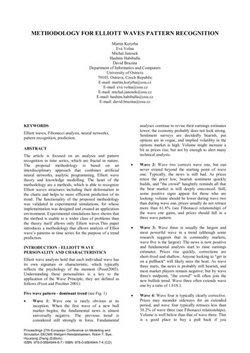
PEC Reflection: ApplicationsRadar calibration with metallic:Reflection in the direction of incidence: dihedral trihedral (corner reflector)Buoy with dihedralRadar image with corner reflectorsSatellite radarcalibration2712.11.2018Chapter 2: Radio Wave Propagation FundamentalsInstitute of Radio Frequency Engineeringand Electronics
Two-RayPropagation Model2812.11.2018Chapter 2: Radio Wave Propagation FundamentalsInstitute of Radio Frequency Engineeringand Electronics
GeometryTd1RzTd2air (𝜺𝒓 𝟏)ground (𝜺𝒓 )zRjjrdTwo-Ray model is based on geometrical optics and predicts large-scale fading2912.11.2018Chapter 2: Radio Wave Propagation FundamentalsInstitute of Radio Frequency Engineeringand Electronics
AssumptionsAssumptions in two-ray model: ground is PEC d zT,zRdObservations: the received power PR oscillates like a sin2 or cos2 with distance the minimum value of PR is 0 the maximum value of PR is 4 · PR,freespace ( 6 dB)3012.11.2018Chapter 2: Radio Wave Propagation FundamentalsInstitute of Radio Frequency Engineeringand Electronics
Large DistancesConditions: d k0zTzR cos2x 1 sin2x x2Observations: parallel pol: 20 dB / decade, perpendicular pol: 40 dB / decade perpendicular pol: independent on frequency perpendicular pol: antenna height gain (double zT or zR quadruple PR)3112.11.2018Chapter 2: Radio Wave Propagation FundamentalsInstitute of Radio Frequency Engineeringand Electronics
BreakpointDefinition:The breakpoint is the distancewhere the argument of thesin2 and cos2 terms equals 0.510.5Beyond the01breakpoint thereare no oscillations!0.5003212.11.20180.511.5Chapter 2: Radio Wave Propagation Fundamentals22.5Institute of Radio Frequency Engineeringand Electronics
Polarization Dependenceperpendicular polarizationparallel polarization1/d26 dB1/d26 dB6 dBdependenton frequency1/d26 dB1/d4independenton frequency3312.11.2018Chapter 2: Radio Wave Propagation FundamentalsInstitute of Radio Frequency Engineeringand Electronics
Frequency Dependencef 900 MHzf 4 GHzdbreakpointdbreakpointdistances of notches l3412.11.2018Chapter 2: Radio Wave Propagation FundamentalsInstitute of Radio Frequency Engineeringand Electronics
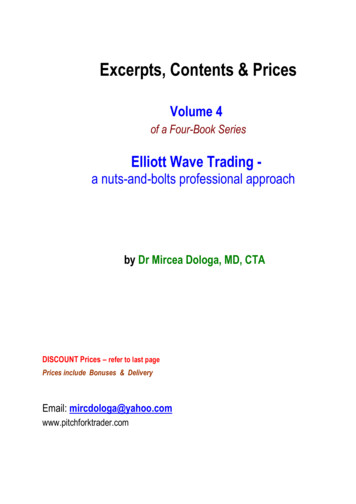
Path Loss Predictionpath lossheight z(above ground)80dB 200mvertical (parallel)polarization50m0m130dB0m range coordinate r (distance from transmitter) 2000mheight z(above ground)horizontal (perpendicular)polarizationpath loss80dB 200m50m0m130dB3512.11.20180m range coordinate r (distance from transmitter) 2000mChapter 2: Radio Wave Propagation FundamentalsInstitute of Radio Frequency Engineeringand Electronics
DiffractionDiffraction on Absorbing Half-Plates3612.11.2018Chapter 2: Radio Wave Propagation FundamentalsInstitute of Radio Frequency Engineeringand Electronics
Knife Edge Diffraction: GeometryzsecondarysphericalwavesrTz HrRH 0ytransmitterdTxdRreceiver obstacle: semi-infinite, infinitely thin, absorbing plate calculate behavior behind the plate: Huygens’ principle wave propagation behind the plate: sum of secondary waves3712.11.2018Chapter 2: Radio Wave Propagation FundamentalsInstitute of Radio Frequency Engineeringand Electronics
Knife Edge Diffraction: ModelAssumptions in knife edge model: cylindrical waves (2D problem) Tx and Rx at same height H dT,dRField-strength relative to free space (no obstacle):EE H 21 1 1 C ( ) S ( ) 2 2 2 H3812.11.2018Fresnel Integrals22 1 1 l dT d R Chapter 2: Radio Wave Propagation FundamentalsInstitute of Radio Frequency Engineeringand Electronics
Knife Edge Diffraction: Electric Field (I)shadow region- 6 dBlit region H3912.11.20182 1 1 l dT d R Chapter 2: Radio Wave Propagation FundamentalsInstitute of Radio Frequency Engineeringand Electronics
Knife Edge Diffraction: Electric Field (II)shadow region- 6 dBlit region 0EE H dBif 0.78 6.9 20 log 0.1 0.1 2 1 if 0.784012.11.2018Chapter 2: Radio Wave Propagation FundamentalsInstitute of Radio Frequency Engineeringand Electronics
Knife Edge Diffraction: Frequency Dependence (I) field strength normalizedto free space levelisotropic Tx antennasemi-infinite, absorbing platef 1 GHz, 3 GHz, 10 GHzdiffraction loss increases with frequency 4112.11.2018Chapter 2: Radio Wave Propagation Fundamentalsf for 1Institute of Radio Frequency Engineeringand Electronics
Knife Edge Diffraction: Frequency Dependence (II)SINGLE KNIFE EDGE DIFFRACTION ,FREQUENCY DEPENDENCEshadow / lit region-6 dBf transmitter height obstacle heightdistance transmitter to knife edge 1000mdistance knife edge to receiver 100m4212.11.2018Chapter 2: Radio Wave Propagation FundamentalsInstitute of Radio Frequency Engineeringand Electronics
Fresnel EllipsoidsNth Fresnel zone is bounded by an ellipsoid, wherethe Tx-Rx-path is N half wavelengths longer thanthe direct Tx-Rx-path dT dR between Tx and Rxd FN dT d R N l 2rF1TxRxdTdR1st Fresnel ellipsoidNth Fresnel ellipsoidRadius of Nth Fresnel ellipsoid4312.11.2018Chapter 2: Radio Wave Propagation FundamentalsInstitute of Radio Frequency Engineeringand Electronics
When to Neglect the Knife Edge Diffraction?Relate Fresnel radius RFN with diffraction parameter :-12If the knife edge does not extend into 1st Fresnelzone, then the error compared to free spacepropagation is less than 1.1 dB:If the knife edge does not extend into the 1st Fresnel zone,then knife edge diffraction can be neglected4412.11.2018Chapter 2: Radio Wave Propagation FundamentalsInstitute of Radio Frequency Engineeringand Electronics
Fresnel Ellipsoids: ExampleRxTxdRdTRF1dT dR l0/24512.11.2018Chapter 2: Radio Wave Propagation FundamentalsInstitute of Radio Frequency Engineeringand Electronics
ScatteringScattering of Incident Energy on Rough Surfaces4612.11.2018Chapter 2: Radio Wave Propagation FundamentalsInstitute of Radio Frequency Engineeringand Electronics
Different Types of Scatteringpoint scatteringSimple targets(plate, sphere,cylinder, etc.)4712.11.2018distributed scatteringrough surface scatteringChapter 2: Radio Wave Propagation Fundamentalsvolume scatteringInstitute of Radio Frequency Engineeringand Electronics
From Specular Reflection to Incoherent Scatteringspecular reflectioncoherent scatteringdiffuse scatteringRoughness criteria:Roughness paremeter:sh: RMS heightL: correlation length i sLshRayleigh:Fraunhofer:sh sh l08cos il032cos i 4812.11.2018Chapter 2: Radio Wave Propagation Fundamentals Institute of Radio Frequency Engineeringand Electronics
Multipath PropagationCombination of all Wave Propagation Effects4912.11.2018Chapter 2: Radio Wave Propagation FundamentalsInstitute of Radio Frequency Engineeringand Electronics
Propagation PhenomenarefractionzTreflectionzRpath Ndiffractiontransmitter QTiyTxTyTiQRi receiverpath ixRyRipath 1yRscatteringfree spacepropagation:- line of sight- no multipathreflection:- plane wave reflectionscattering:- Fresnel coefficients- volume scatteringdiffraction:- knife edge diffraction- rough surface scatteringrefraction in thetroposphere:- not consideredIn general multipath propagation leads to fading at the receiver site5012.11.2018Chapter 2: Radio Wave Propagation FundamentalsInstitute of Radio Frequency Engineeringand Electronics
Path Loss Prediction over Natural Terrain80 mpath lossheight70 dB f 435 MHz Tx height 16.4 m vertical polarization f 1900 MHz16.4 m150 dBdistance7.95 km80 mpath lossheight80 dB0m0 km16.4 m160 dB5112.11.20180m0 kmdistanceChapter 2: Radio Wave Propagation Fundamentals7.95 kmInstitute of Radio Frequency Engineeringand Electronics
13 Institute of Radio Frequency Engineering and Electronics Snell'sLaw of Reflection 12.11.2018 Chapter 2: Radio Wave Propagation Fundamentals 1 2 i r t surface large compared to the wave length smooth surface (otherwise scattering) three angles: - incidence - reflection - transmission / refraction *full derivation in Arthur Schuster: "An Introduction to the Theory of Optics"