Transcription
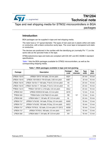
STL33N60M2DatasheetN-channel 600 V, 0.115 Ω typ., 22 A MDmesh M2Power MOSFET in a PowerFLAT 8x8 HV packageFeatures54321PowerFLAT 8x8 HVOrder codeV DS @ T JmaxRDS(on)maxIDSTL33N60M2650 V0.135 Ω22 A Extremely low gate chargeExcellent output capacitance (COSS) profile 100% avalanche testedZener-protectedDrain(5)Applications Gate(1)Driversource (2)Switching applicationsLLC converters, resonant convertersDescriptionPowersource (3, 4)NG1DS2PS34D5ZThis device is an N-channel Power MOSFET developed using MDmesh M2technology. Thanks to its strip layout and an improved vertical structure, the deviceexhibits low on-resistance and optimized switching characteristics, rendering itsuitable for the most demanding high efficiency converters.Product status linkSTL33N60M2Product summaryOrder codeSTL33N60M2Marking33N60M2PackagePowerFLAT 8x8 HVPackingTape & reelDS9512 - Rev 4 - June 2019For further information contact your local STMicroelectronics sales office.www.st.com
STL33N60M2Electrical ratings1Electrical ratingsTable 1. Absolute maximum ratingsSymbolParameterValueUnit 25VVGSGate-source voltageID (1)Drain current (continuous) at TC 25 C22AID (1)Drain current (continuous) at TC 100 C13.8AIDM (2)Drain current (pulsed)88APTOTTotal power dissipation at TC 25 C150W5A450mJIAREASAvalanche current, repetitive or not-repetitive (pulse width limited by Tj max)Single pulse avalanche energy(starting Tj 25 C, ID IAR, VDD 50 V)dv/dt (3)Peak diode recovery voltage slope15V/nsdv/dt (4)MOSFET dv/dt ruggedness50V/nsTstgStorage temperature range- 55 to 150 C150 CValueUnitTjOperating junction temperature range1. The value is limited by package.2. Pulse width limited by safe operating area.3. ISD 22 A, di/dt 400 A/µs, VDS( peak) V(BR)DSS, VDD 400 V.4. VDS 480 V.Table 2. Thermal dataSymbolParameterRthj-caseThermal resistance junction-case0.83 C/WRthj-pcb (1)Thermal resistance junction-pcb45 C/W1. When mounted on FR-4 board of 1 inch², 2oz Cu.DS9512 - Rev 4page 2/15
STL33N60M2Electrical characteristics2Electrical characteristics(TC 25 C unless otherwise specified)Table 3. On /off statesSymbolV(BR)DSSIDSSIGSSParameterTest conditionsDrain-sourcebreakdown voltageVGS 0 V, ID 1 mAZero gate voltageVGS 0 V, VDS 600 Vdrain currentGate-body leakagecurrentVGS 0 V, VDS 600 V, TC 125 CMin.Typ.600Gate thresholdvoltageVDS VGS, ID 250 µARDS(on)Static drain-sourceon- resistanceVGS 10 V, ID 11 AUnitV1µA100µA F-2.5-pF(1)VDS 0 V, VGS 25 VVGS(th)Max.21. Defined by design, not subject to production test.Table 4. DynamicSymbolCissCossParameterTest conditionsInput capacitanceOutput capacitanceVDS 100 V, f 1 MHz,VGS 0 VCrssReverse transfercapacitanceCoss eq. (1)Equivalent outputcapacitanceVDS 0 to 480 V, VGS 0 V-135-pFRGIntrinsic gateresistancef 1 MHz open drain-5.2-ΩQgTotal gate chargeVDD 480 V, ID 26 A-45.5-nCQgsGate-source chargeVGS 0 to 10 V-9.9-nCQgdGate-drain charge(see Figure 15. Gate charge test circuit)-18.5-nC1. Coss eq. is defined as a constant equivalent capacitance giving the same charging time as Coss when VDS increases from 0to 80% VDSS.Table 5. Switching timesSymboltd(on)trtd(off)tfDS9512 - Rev 4ParameterTest conditionsMin.Typ.Max.UnitTurn-on delay timeVDD 300 V, ID 13 A-16-nsRise timeRG 4.7 Ω, VGS 10 V-9.6-nsTurn-off delay time(see Figure 14. Switching times testcircuit for resistive load andFigure 19. Switching time waveform)-109-ns-9-nsFall timepage 3/15
STL33N60M2Electrical characteristicsTable 6. Source drain diodeSymbolParameterTest conditionsMin.Typ.Max.UnitISDSource-drain current-22AISDM (1)Source-drain current(pulsed)-88AVSD (2)Forward on voltageISD 22 A, VGS 0 V-1.6VtrrReverse recoverytimeISD 26 A, di/dt 100 A/µsQrrReverse recoverychargeIRRMReverse recoverycurrenttrrReverse recoverytimeQrrReverse recoverychargeIRRMReverse recoverycurrentVDD 60 V (see Figure 16. Test circuitfor inductive load switching and dioderecovery times)ISD 26 A, di/dt 100 A/µsVDD 60 V, Tj 150 C(see Figure 16. Test circuit forinductive load switching and dioderecovery times)-375ns-5.6µC-30A-478ns-7.7µC-32.5A1. Pulse width limited by safe operating area.2. Pulsed: pulse duration 300 µs, duty cycle 1.5%.DS9512 - Rev 4page 4/15
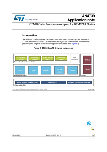
STL33N60M2Electrical characteristics (curves)2.1Electrical characteristics (curves)Figure 1. Safe operating areaFigure 2. Thermal impedanceZth PowerFLAT 8x8 HVKδ 0.50.20.1-1100.050.02Zth K*R thJ-cδ t p/Ƭ0.01Single pulsetp-210 -510Figure 3. Output characteristicsVGS 7, 8, 9, 10V6010Ƭ-2-3tp (s)1010Figure 4. Transfer characteristicsGIPG080720141147MTID (A)-4GIPG080720141423MTID(A)606V5050VDS 17V40405V3030202010104V001051520VDS(V)Figure 5. Gate charge vs gate-source voltageGIPG230420141134MTVDSVGS(V)(V)VDD 480VID 26A12500VDS1040000264810VGS(V)Figure 6. Static drain-source on-resistanceGIPG090720140852MTRDS(on)(Ω)VGS 10V0.1220.1200.11883000.1166200420DS9512 - Rev 4010203040500.1141000.1120Qg (nC)0.11005101520ID(A)page 5/15
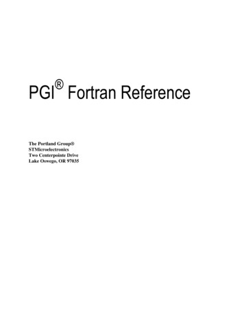
STL33N60M2Electrical characteristics (curves)Figure 8. Normalized gate threshold voltage vstemperatureFigure 7. Capacitance TVGS(th)(norm)ID 0010VDS(V)Figure 9. Normalized on-resistance vs 50255075TJ( C)100Figure 10. Normalized V(BR)DSS vs temperatureGIPG090720141001MTV(BR)DSS(norm)VGS 10V1.112.3ID .90.950.70.5-50 -250.930.91-502505075 100TJ( C)Figure 11. Source-drain diode forward TJ( C)75 100Figure 12. Output capacitance stored energyGIPG230420141137MTEoss(µJ)121.2TJ -50 C10180.860.60.4TJ 150 CTJ 25 C420.200 2DS9512 - Rev 4468 10 12 14 16 18 20ISD(A)00100200300400500600VDS(V)page 6/15
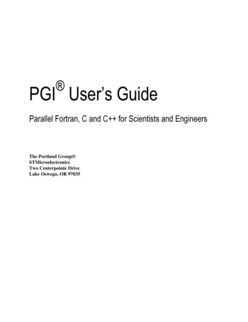
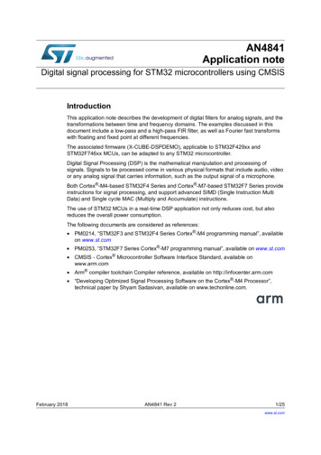
STL33N60M2Electrical characteristics (curves)Figure 13. Maximum avalanche energy vs temperatureEAS(mJ)GADG070220191439EAS400300ID 5 A,VDD 50 V2001000-75DS9512 - Rev 4-252575125TJ ( C)page 7/15
STL33N60M2Test circuits3Test circuitsFigure 15. Gate charge test circuitFigure 14. Switching times test circuit for resistive loadVDD12 VRL VDVGSµFVDDIG CONSTVGSRG1 kΩ100 nF3.3µF220047 kΩ pulse widthD.U.T.2200μFPWD.U.T.100 Ω2.7 kΩVG47 kΩGND1(driver signal)GND2(power)1 kΩGND1AM15855v1GND2AM01469v2Figure 16. Test circuit for inductive load switching anddiode recovery timesAAD.U.T.FASTDIODEFigure 17. Unclamped inductive load test circuitALDGSL 100µHBBD25ΩVD3.3µFB 1000µF2200µF3.3µF 8v1AM15857v1Figure 19. Switching time waveformFigure 18. Unclamped inductive 512 - Rev 4page 8/15
STL33N60M2Package information4Package informationIn order to meet environmental requirements, ST offers these devices in different grades of ECOPACK packages,depending on their level of environmental compliance. ECOPACK specifications, grade definitions and productstatus are available at: www.st.com. ECOPACK is an ST trademark.4.1PowerFLAT 8x8 HV package informationFigure 20. PowerFLAT 8x8 HV package outline8222871 Rev 4DS9512 - Rev 4page 9/15
STL33N60M2PowerFLAT 8x8 HV package informationTable 7. PowerFLAT 8x8 HV mechanical dataRef.Dimensions (in 0E12.652.752.85E24.254.354.45eL0.052.00 BSC0.400.500.60Figure 21. PowerFLAT 8x8 HV footprint8222871 REV 4 footprintNote:DS9512 - Rev 4All dimensions are in millimeters.page 10/15
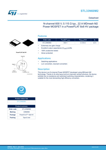
STL33N60M2PowerFLAT 8x8 HV packing information4.2PowerFLAT 8x8 HV packing informationFigure 22. PowerFLAT 8x8 HV tapeP2 (2.0 0.1)T (0.30 0.05)P0 (4.0 0.1)D0 ( 1.55 0.05)D1 ( 1.5 Min)P1 (12.00 0.1)W (16.00 0.3)F (7.50 0.1)B0 (8.30 0.1)E (1.75 0.1)A0 (8.30 0.1)K0 (1.10 0.1)Note: Base and Bulk qu antity 3000 pcs8229819 Tape revANote:All dimensions are in millimeters.Figure 23. PowerFLAT 8x8 HV package orientation in carrier tapeDS9512 - Rev 4page 11/15
STL33N60M2PowerFLAT 8x8 HV packing informationFigure 24. PowerFLAT 8x8 HV reel8229819 Reel revANote:DS9512 - Rev 4All dimensions are in millimeters.page 12/15
STL33N60M2Revision historyTable 8. Document revision historyDateRevision26-Jun-20131ChangesFirst release.Updated the title, the features and the description in cover page. Documentstatus promoted from preliminary data to production data.23-Jul-20142Updated Figure 1: "Internal schematic diagram", Section 1: "Electrical ratings",Section 2: "Electrical characteristics".Added Section 2.1: "Electrical characteristics (curves)"Updated Section 3: "Test circuits", Section 4.1: "PowerFLAT 8x8 HVpackage mechanical data".Updated: cover image and Figure 1: "Internal schematic diagram"Table 2: "Absolute maximum ratings", Table 3: "Thermal data" andTable 6: "Switching times"20-Nov-20153Updated: Figure 3: "Thermal impedance"Updated: Section 5: "Test circuits"Updated: Section 6.1: "PowerFLAT 8x8 HV package mechanical data"Minor text changesUpdate Section 1 Electrical ratings.11-Jun-20194Added Figure 13. Maximum avalanche energy vs temperature.Minor text changes.DS9512 - Rev 4page 13/15
STL33N60M2ContentsContents1Electrical ratings . . . . . . . . . . . . . . . . . . . . . . . . . . . . . . . . . . . . . . . . . . . . . . . . . . . . . . . . . . . . . . . . . .22Electrical characteristics. . . . . . . . . . . . . . . . . . . . . . . . . . . . . . . . . . . . . . . . . . . . . . . . . . . . . . . . . . . 32.1Electrical characteristics (curves) . . . . . . . . . . . . . . . . . . . . . . . . . . . . . . . . . . . . . . . . . . . . . . . . . 53Test circuits . . . . . . . . . . . . . . . . . . . . . . . . . . . . . . . . . . . . . . . . . . . . . . . . . . . . . . . . . . . . . . . . . . . . . . .84Package mechanical data . . . . . . . . . . . . . . . . . . . . . . . . . . . . . . . . . . . . . . . . . . . . . . . . . . . . . . . . . . 94.1PowerFLAT 8x8 HV package information . . . . . . . . . . . . . . . . . . . . . . . . . . . . . . . . . . . . . . . . . . 94.2PowerFLAT 8x8 HV packing information . . . . . . . . . . . . . . . . . . . . . . . . . . . . . . . . . . . . . . . . . . 10Revision history . . . . . . . . . . . . . . . . . . . . . . . . . . . . . . . . . . . . . . . . . . . . . . . . . . . . . . . . . . . . . . . . . . . . . . .13DS9512 - Rev 4page 14/15
STL33N60M2IMPORTANT NOTICE – PLEASE READ CAREFULLYSTMicroelectronics NV and its subsidiaries (“ST”) reserve the right to make changes, corrections, enhancements, modifications, and improvements to STproducts and/or to this document at any time without notice. Purchasers should obtain the latest relevant information on ST products before placing orders. STproducts are sold pursuant to ST’s terms and conditions of sale in place at the time of order acknowledgement.Purchasers are solely responsible for the choice, selection, and use of ST products and ST assumes no liability for application assistance or the design ofPurchasers’ products.No license, express or implied, to any intellectual property right is granted by ST herein.Resale of ST products with provisions different from the information set forth herein shall void any warranty granted by ST for such product.ST and the ST logo are trademarks of ST. For additional information about ST trademarks, please refer to www.st.com/trademarks. All other product or servicenames are the property of their respective owners.Information in this document supersedes and replaces information previously supplied in any prior versions of this document. 2019 STMicroelectronics – All rights reservedDS9512 - Rev 4page 15/15
1 Electrical ratings Table 1. Absolute maximum ratings Symbol Parameter Value Unit VGS Gate-source voltage 25 V ID (1) Drain current (continuous) at TC 25 C 22 A ID (1) Drain current (continuous) at TC 100 C 13.8 A IDM (2) Drain current (pulsed) 88 A PTOT Total power dissipation at TC 25 C 150 W IAR Avalanche current, repetitive or not-repetitive (pulse width limited by Tj max) 5 A