Transcription
See discussions, stats, and author profiles for this publication at: An Introduction to Microprocessor 8085Book · January 2010CITATIONREADS1231,6801 author:D.K. KaushikShobhit University, Gangoh (Saharanpur) India44 PUBLICATIONS 39 CITATIONSSEE PROFILESome of the authors of this publication are also working on these related projects:Modeling View projectAll content following this page was uploaded by D.K. Kaushik on 25 August 2014.The user has requested enhancement of the downloaded file.
AN INTRODUCTION TO MICROPROCESSOR 8085ByDr. D. K. KaushikPrincipal, Manohar Memorial (P.G.) College,Fatehabad (Haryana) IndiaDhanpat Rai Publishing co., New Delhi
AN INTRODUCTION TO MICROPROCESSOR 8085Chapter 1Evolution and History of Microprocessors1.1 Introduction1.2 Evolution/History of Microprocessors1.3 Basic Microprocessor System1.3.1 Address Bus1.3.2 Data Bus1.3.3 Control Bus1.4 Brief Description of 8-Bit Microprocessor 8080A1.5 Computer Programming Languages1.5.1 Low-Level Programming Language1.5.2 High-Level Programming LanguageChapter 2SAP – I2.12.22.32.4Architecture of SAP – IInstruction Set of SAP-I ComputerProgramming of SAP-I ComputerWorking of SAP-I Computer2.4.1 Fetch Cycle2.4.2 Execution Cycle2.5 Hardware Design of SAP-I Computer2.5.1 Design of Program Counter2.5.2 Memory Unit2.5.3 Instruction Register2.5.4 Controller-Sequencer2.5.5 Accumulator2.5.6 Adder-Subtractor2.5.7 B-Register2.5.8 Output RegisterChapter 33.13.23.33.43.53.63.73.8SAP – IIArchitecture of SAP-II ComputerInstruction Set of SAP-II ComputersMachine Cycle and Instruction CycleAddressing ModesInstruction TypesFlagsAssembly Language ProgrammingDelay CalculationsChapter 4SAP – III4.1 Programming Model of SAP-III Computer4.2 Instruction Set of SAP-III Computer4.2.1 Data Transfer Group4.2.2 Arithmetic Group of Instructions4.2.3 Logic Transfer Group4.2.4 Branch Group
4.2.5 Stack and Input / Output Instructions4.3 Time Delay Introduced by a Register PairChapter 5The 8085 Microprocessor5.1 Architecture of 8085 Microprocessor5.1.1 Register Section5.1.2 Address Buffer and Address-Data Buffer5.1.3 Arithmetic and Logical Unit (ALU)5.1.4 Timing and Control Unit5.1.5 Interrupt Control5.2 Pin Description of 80855.3 Instruction Set of 8085 Microprocessor5.4 Timing Diagram for 8085 Instructions5.4.1 Timing Diagram of MOV reg, M5.4.2 Timing Diagram of MOV M, reg5.4.3 Timing Diagram of MVI reg, data5.4.4 Timing Diagram of MOV reg2, reg15.4.5 Timing Diagram of MVI M, data5.4.6 Timing Diagram of XCHG5.4.7 Timing Diagram of LXI rp, dbyte5.4.8 Timing Diagram of IN byteChapter 6Programming of 80856.1 Simple Progams6.2 Progams on code conversion6.2.1 BCD to Binary Conversion6.2.2 Binary to BCD (Unpacked) Conversion6.2.3 Binary to ASCII Conversion6.2.4 ASCII to Binary Conversion6.3 Progams on addition and subtraction6.4 Progams to find largest or smallest number6.5 Progams to arrange a given series in ascending or descending order6.6 Program on Multiplication6.7 Program on 8-Bit Division6.8 Miscellaneous ProgramsChapter 7Interrupt Instructions of 80857.1 Methods of I/O Operations7.1.1 Memory Mapped I/O7.1.2 I/O Mapped I/O or Isolated I/O7.2 Data Transfer Schemes7.2.1 Programmed I/O Data Transfer7.2.2 Interrupt Driven I/O Data Transfer7.2.3 Direct Memory Access (DMA) Data Transfer7.3 The 8085 Interrupts7.4 Software Interrupts7.5 Hardware Interrupts7.6 Interrupt Control Circuit7.7 Interrupt Instructions
7.8 Serial Input and Output Data TransferChapter 8Programmable Peripheral Interface (PPI) 8255A8.18.28.38.48.5Details of PPI IC 8255AOperational Modes of 8255AControl Word Format for 8255AProgramming in Mode 0Programming in Mode 1 (strobed Input/Output)8.5.1 Input Control Signals in Mode 18.5.2 Output Control Signals in Mode 18.6 Programming in Mode 2 (Strobed Bidrectional Bus I/O)8.7 Bit Set/Reset (BSR) ModeChapter 9Programmable Interval Timer/Counter: 82539.1 INTEL Programmable Interval Timer 82539.2 Block Diagram of 82539.3 Logics for Counters9.4 Control Word Format of 82539.5 Interfacing and programming of 82539.6 Programming of 8253 in Mode 0: Interrupt on Terminal Count9.7 Programming of 8253 in Mode 1: Programmable One Shot9.8 Programming of 8253 in Mode 2: Rate Generator9.9 Programming of 8253 in mode 3: Square Wave Generator9.10 Programming of 8253 in mode 4: Software Triggered StrobeChapter 10 Programmable Keyboard and Display Interface: 827910.110.210.310.410.5INTEL Programmable Keyboard/Display Interface 8279Block Diagram of 8279Functional Description of 8279Key Board SanScanned Keyboard10.5.1 Two-key Lockout10.5.2 N-key Rollover10.6 Scanned Sensor Matrix10.7 Strobed Input10.8 Display Interface10.9 Display Modes10.9.1 Left Entry Mode (Type Writer Mode)10.9.2 Right Entry Mode (Calculator Mode)10.10 Programming of 827910.10.1 Keybaord/Display Mode Set10.10.2 Program Clock10.10.3 Read FIFO/Sensor RAM10.10.4 Read Display RAM10.10.5 Write Display RAM10.10.6 Display Write Inhibit/Blanking10.10.7 Clear10.10.8 End Interrupt/Error Mode Set10.11 Status Register (IN Operation)
10.12 Interfacing of 8279 with 8085Chapter 11 Programmable Interrupt Controller: 825911.111.211.311.411.511.611.711.8Programmable Interrupt Controller 8259Block Diagram of 8259Interfacing of 8259A with 8085AVectoring Data Formats for 8259Initialization of 8259Initialization Command Words (ICWs)Operation Command Words (OCWs)Interrupt Modes of 8259A11.8.1 Fully Nested Mode (FNM)11.8.2 Rotating Priority Mode11.8.3 Special Mask Mode11.8.4 Polled Mode11.9 Status Read Operation of 8259Chapter 12 Direct Memory Access Controller: 825712.1 Block Diagram of 825712.1.1 DMA Channels12.1.2 Data Bus Buffer12.1.3 Read/ Write Logic12.1.4 Control Logic12.1.5 Mode Set Register12.1.6 Status Word Register12.2 Programming of 825712.3 DMA Interfacing CircuitChapter 13 Interfacing Data converters: A/D and D/A Converters13.1Digital to Analog Converter13.1.1 Resistive Divider D/A converter13.1.2 Binary Ladder D/A Converter13.2 Performance Criteria for D/A Converter13.3 D/A Converter IC 080813.4 Interfacing of D/A Converter13.5 Microprocessor Compatible D/A Converter13.6 Analog to Digital Converter13.7 Simultaneous A/D Converter13.8 Successive Approximation A/D Converter13.9 Counter or Digital Ramp Type A/D Converter13.10 Single Slope A/D Converter13.11 Dual Slope A/D Converter13.12 ADC 0808/080913.13 A/D Converter Using D/A Converter and SoftwareChapter 14 Serial Communication and Programmable CommunicationInterface
14.114.214.314.414.514.6Serial Data CommunicationModemSerial Communication StandardAsynchronous Software ApproachProgrammable Communication InterfaceBlock Diagram of 8251A14.6.1 Read/Write Control Logic14.6.2 Transmitter Section14.6.3 Receiver Section14.6.4 Modem Control14.7 Interfacing of 8251A14.8 Programming of 8251A14.8.1 Initialization of 8251A in Asynchronous Mode14.8.2 Initialization of 8251A in Synchronous ModeChapter 15 Applications of Real Time Clock with On/Off TimerMicroprocessor Based LED Dial ClockDesign of Microprocessor Based Running lightMicroprocessor Based Automatic School bell systemMicroprocessor Based Traffic Light15.5.1 Another Design of Microprocessor Based Traffic LightMicroprocessor Based Stepper Motor ControlMicroprocessor Based Washing Machine ControllerMicroprocessor Based Water Level ControllerMicroprocessor Based Temperature ControllerAppendices
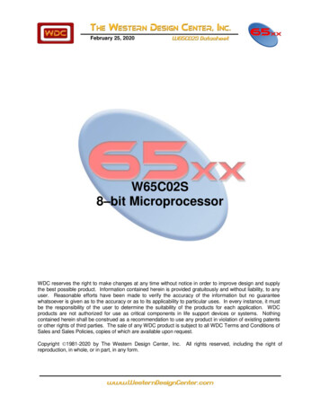
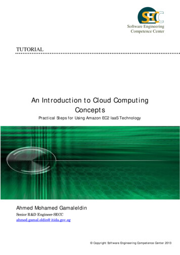
1Evolution and History ofMicroprocessorsTo understand the working and programming of microprocessors, it is verynecessary to know the details of evolution and history of microprocessors which will bediscussed in this chapter. In the succeeding chapters of this book, the detailed discussionon the basics of microprocessors will be made. For the beginners it is very difficult tounderstand the operation of a digital computer as it contains large details, so efforts havebeen made to envisage the operation of a digital computer in step by step manner.1.1 INTRODUCTIONMicroprocessor is a digital device on a chip which can fetch instructions from amemory, decode and execute them i.e. performs certain arithmetic and logical operations,accept data from input device, and send results to output devices. Therefore, amicroprocessor interfaced with memory and Input/ Output devices forms aMicrocomputer. Basically, there are five building blocks of a digital computer namely:Input UnitThrough this unit data and instructions are fed to the memory of thecomputer. The basic purpose of this unit is to read the data into themachine. The program from the memory is read into the machinealong with the input data which are required to solve or compute theproblem by the machine. The typical devices which are used for thispurpose are keyboards, paper tape reader and toggle switches etc.Memory UnitThe memory unit of a digital computer consists of devices which arecapable of storing information. The memory of a computer is usedfor storing two distinct type of information such as data to beprocessed by the computer and program through which the result ofthe desired problem is obtained. Computer program and data arestored in the Memory Unit. This usually consists of chips of bothROMs (Read Only Memories) and RAMs (Random AccessMemories) either bipolar or MOS.
Arithmetic andLogical Unit(ALU)This unit is used for performing arithmetic operations such asAddition, Subtraction, Multiplications, division and other logicaloperations on the data.The control unit guides ALU which of the operations are to beperformed. The sequence of the instructions is controlled by thecontrol unit.Control UnitThe control unit performs the most important function in a computer.It controls all other units and also controls the flow of data from oneunit to another for performing computations. It also sequences theoperations. It instructs all the units to perform the task in a particularsequence with the help of clock pulses.Output UnitAfter processing of the data in the Arithmetic and Logical Unit, theresults are displayed to the output world through this unit. The CRTs(Cathode Ray Tubes), LEDs (Light Emitting Diodes) and Printer etc.form the output unit.In a computer system ALU and Control Unit are combined in one unit calledCentral Processing Unit (CPU). The block diagram of a computer is shown in figure 1.1.Fig. 1.12
The Central Processing Unit is analogous to the human brain as all the decisionsas per the instructions are made by CPU. All other parts are also controlled by this unit. Amicroprocessor is an integrated circuit designed for use as Central Processing Unit of acomputer. The CPU is the primary and central player in communicating with devicessuch as memory, input and output. However, the timing of communication process iscontrolled by the group of circuits called control unit.The term ‘Microprocessor’ came into existence, in 1971, when the IntelCorporation of America, developed the first microprocessor (INTEL-4004) which is a 4bit microprocessor ( µ p). A microprocessor is a programmable digital electroniccomponent that incorporates the functions of a Central Processing Unit (CPU) on singlesemi-conducting Integrated Circuits (ICs). As such, a system with microprocessor as anintegral part is termed as a microprocessor based system. When a computer ismicroprocessor based, it is called a microcomputer ( µ c).A microprocessor is specified by its ‘Word Size’, e.g. 4-bit, 8-bit, 16-bit etc. Bythe term ‘word size” means the number of bits of data that is processed by themicroprocessor as a unit. For example, an 8-bit microprocessor performs variousoperations on 8-bit data. It also specifies the width of the data bus. As discussed above, amicrocomputer consists of input/ output devices, and memory, in addition tomicroprocessor which acts its CPU. In fact CPU is commonly referred to microprocessor( µ p). Microprocessors made possible the advent of the microcomputer in the mid-1970s.Before this period, electronic CPUs were typically made from bulky discrete switchingdevices. Later on small-scale integrated circuits were used to design the CPUs. Byintegrating the processor onto one or very few large-scale integrated circuit package(containing the equivalent of thousands or millions of discrete transistors), the cost ofprocessor was greatly reduced.The evolution of microprocessors has been known to follow Moore’s law when itcomes to steadily increasing performance over the years. This law suggests that thecomplexity of an integrated circuit, with respect to minimum component cost, doubles inevery 18 months. This dictum has generally proven true since the early 1970’s. This leadto the dominance of microprocessors over every other form of computer; every systemfrom the largest mainframes to the smallest hand held computers now uses amicroprocessor as its core.The microprocessor based systems play significant role in the every functioningof industrialized societies. The microprocessor can be viewed as a programmable logicdevice that can be used to control processes or to turn on/off devices. So themicroprocessor can be viewed as a data processing unit or a computing unit of acomputer. The microprocessor is a programmable integrated device that has computingand decision making capability similar to that of the central processing unit (CPU) of acomputer. Nowadays, the microprocessor is being used in a wide range of products calledmicroprocessor based products or systems. The microprocessor communicates andoperates in the binary numbers 0 and 1, called bits. Each microprocessor has a fixed set3
of instructions in the form of binary pattern called a machine language. However, it isdifficult for human beings to communicate in the language of 0s and 1s. Therefore, thebinary instructions are given abbreviated names, called mnemonics, which form theassembly language for a given microprocessor.1.2 EVOLUTION/HISTORY OF MICROPROCESSORSAn English Mathematician Charles Babbage was the firs
1.4 Brief Description of 8-Bit Microprocessor 8080A 1.5 Computer Programming Languages 1.5.1 Low-Level Programming Language 1.5.2 High-Level Programming Language Chapter 2 SAP – I 2.1 Architecture of SAP – I 2.2 Instruction Set of SAP-I Computer 2.3 Programming of SAP-I Computer 2.4 Working of SAP-I Computer 2.4.1 Fetch Cycle 2.4.2 Execution Cycle 2.5 Hardware Design of SAP-I