Transcription
ManualPROFIBUS Tester 4BC-600-PBFW version 1.13 (rev. 17)Revision 2013-05-31
Copyright 2013 Softing Industrial Automation GmbHNo part of this manual may be reproduced, photocopied, stored on a retrievalsystem, transmitted, processed or translated without the express prior writtenconsent.
ContentsIntroduction11.1 General1.2 Test Functions1.2.1 Stand-alone mode of operation1.2.2 PC mode of operation2Delivery Scope3Optional Accessories3.1 D-sub adapter cable for testing live systems3.2 Adapter Set for M12 Connection Technology3.3 Fieldbus Shield Digital Leakage Current Clamp3.4 Portable Power Supply3.5 Service Interface for PROFIBUS DP3.5.1 Connection Type D-sub3.5.2 Connection Type M124Connectors and Controls5Power Supply and Auto Power On5.1 Power-Up Behaviour without USB Connection5.2 Power-Up Behaviour when USB Connected6Software Installation6.1 Connection to a PC7Connection to PROFIBUS7.1 Basics7.1.1 Warning notice for testing a live bus7.1.2 Connection types7.1.3 Adapter cable7.1.4 Strain relief7.1.5 Test locations7.2 Simple Connection for Tests During System Shutdown7.3 Connection for Testing a Live Bus7.3.1 Connection via D-sub connector with service socket7.3.2 Direct cable connection7.3.3 Connection via M12 18181920212223
7.4 Master Simulator and Topology Scan7.4.1 Special case: Active devices at both ends of the bus8Display and Control in Stand-Alone Mode8.1 Main Display8.2 Operating Concept8.3 Functions8.3.1 Live Status function8.3.1.1 Bus status summary8.3.1.2 Segment status 18.3.1.3 Segment status 28.3.1.4 Station status8.3.2 Quick Test function8.3.3 Trend function8.3.4 Master Simulator function8.3.5 Settings and help functions9Data Import into the PC10 Firmware Update11 Maintenance and Servicing12 Troubleshooting13 Specifications14 General Notes14.1 Lithium Battery14.2 CE 424242
Introduction1ManualIntroduction1.1GeneralThe PROFIBUS Tester 4 is a powerful tool that allows full testing of the busphysics and bus communication on PROFIBUS DP segments.Using the integrated master simulator, you can also test the bus physics if thePLC is currently not in operation, or individually check “suspicious” busstations.The tool is powered either through an external AC adapter, by directconnection to 24 VDC or through an optional portable power supply unit.1.2Test FunctionsThe PROFIBUS Tester 4 automatically detects the baud rate or open circuitvoltage as soon as you connect it to a PROFIBUS DP segment.You can then choose between two modes of operation for bus testingdepending on if you run it in stand-alone mode, or connect the PROFIBUSTester 4 to a PC or notebook. If required the master simulator can be enabledin both modes if no other master is active.1.2.1Stand-alone mode of operationIn the stand-alone mode three test functions with simultaneous analysis of busphysics and bus communication are available:1. The Live Status shows the bus status and the details of the analysisin real-time on the display.2. To evaluate the bus health up to ten Quick Tests can be executed,stored internally and imported by the PC software then.3. To locate the causes of sporadic bus faults the long-term Trend logsdata for up to 41 days and stores them internally for later import by thePC software.Page 6 2013
BC-600-PB1.2.2IntroductionPC mode of operationThe PC software provides many additional features for performing, analyzingand managing bus tests. Quick Tests and Trends stored in the tool can beimported.In the PC mode four main functions are available. Two of them providecomplex functionality that only experts need and that are accessed separatelyfrom the standard functionality.Standard functions:1. The Network Status is a collection of information and test datarelating to a PROFIBUS network. It provides the basis for acomprehensive evaluation of the bus health.ooooQuick test and user-controlled test with simultaneous analysisof bus physics and bus communicationTopology scanTest reportMaster simulator2. If sporadic faults occur in a PROFIBUS installation, the quality indexesand critical protocol events should be monitored with the long-termTrend over a prolonged period to locate the causes of bus problems.Expert functions:3. The function Frames enables the classic frame analysis.4. The Oscilloscope permits the detail analysis of signal waveforms.SoftingPage 7
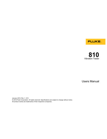
Delivery Scope2ManualDelivery ScopeThe PROFIBUS Tester 4 comes in a carrying case comprising: Test tool with RS485 interfaceWide-range power supply with European and US mains power cablesConnecting cable for direct power supply with 24 VDCRS485 D-sub adapter cable BC-600-PB-CB-DSUB-2 “Standard”(cable petrol blue, light connector) for PROFIBUS DPUSB cable, 3 mTerminal block for trigger input/outputCD-ROM with driver software, PC software and detailed integratedhelp system in English and GermanPROFIBUS Tester 4 user manual and Getting Started manual for thePROFIBUS Diagnostics Suite PC softwareFig. 1: BC-600-PB with carrying casePage 8 2013
BC-600-PB33.1Optional AccessoriesOptional AccessoriesD-sub adapter cable for testing live systemsThis D-sub adapter cable is optimized for reduced influence on livePROFIBUS DP segment operation. Thereby it is most suitable for testing ofrunning plants. The risk of critical influences on bus operation which can causea plant standstill is significantly reduced. Attention: Using this cable it is notpossible to use the both active functions master simulator and topologydetection (see page 23).Fig. 2: D-sub adapter cable with reduced influence on bus operationSofting Order No.: BC-600-PB-CB-DSUB-13.2Adapter Set for M12 Connection TechnologyUsing the M12 adapter set, you can connect the PROFIBUS Tester 4 to fielddevices with M12 connectors. The set comprises an M12 adapter cable withspecial pin layout and an M12 terminating resistor that you can screw on, ifrequired.Fig. 3: Special adapter set for M12Softing Order No.: BC-600-PB-CB-M12SoftingPage 9
Optional Accessories3.3ManualFieldbus Shield Digital Leakage Current ClampWhen routing PROFIBUS cables in high-interference environments,electromagnetic interference can affect the signal quality. By measuring theshield currents with the digital leakage current clamp, you can locate EMCproblem areas and take appropriate countermeasures. The digital leakagecurrent clamp is supplied in a handy case, including measuring cables. Thereis also an empty compartment for the fieldbus shield digital leakage currentclamp in the carrying case of the BC-600-PB.Fig. 4: Fieldbus shield digital leakage current clampSofting Order No.: PB-LSZ-CHB33.4Portable Power SupplyThe portable power supply unit allows up to 4 hours of portable operation. Thepower supply kit also includes a charger and a carrying case. Attention: Mainsconnector type of charger station available for Europe only.Fig. 5: Portable power supplySofting Order No.: BC-MOST-PBPage 10 2013
BC-600-PB3.5Optional AccessoriesService Interface for PROFIBUS DP3.5.1Connection Type D-subThe D-sub service interface provides a PROFIBUS access point for testing ifthe existing D-sub connectors have no service socket or if the bus stations areconnected via a terminal block. The service interface can power theterminating resistor of the D-sub connector. You can thus use it as an activebus termination at the beginning or end of the bus.If the PLC allows dropping and adding bus stations on the live bus, you willneed this external bus termination to be able to exchange the first and last busstations without causing problems on the bus.The compact unit is rail mounted like a terminal block and powered by anexternal 24 VDC power supply. The package includes an 90 angledPROFIBUS connector with a switchable terminating resistor.Fig. 6: D-sub service interface for testing a live busSofting Order No.: BC-PBMB-PB-SSoftingPage 11
Optional Accessories3.5.2ManualConnection Type M12The M12 service interface comprises an IP68 rated T piece, an end cap for theservice output of the T piece, and a 1m PROFIBUS DP cable fitted with amale/female M12 connector on each end.Fig. 7: M12 service interface for testing a live busSofting Order No.: BC-M12DP-PBPage 12 2013
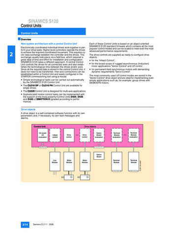
BC-600-PB4Connectors and ControlsConnectors and ControlsRS485Connection to PROFIBUS DPDisplayStatus display & operationFunction key 2Detail selectionFunktionstaste 3StartFunction key 1Function selectionFunktionstaste 4Back/CancelPowerConnection topower supply24 VDCUSBConnection to notebook/PCStatus LEDTrigger inputStatus LEDTrigger OutputDetail view:Terminal block fortrigger input/outputFig. 8: Connectors and status displays on the BC-600-PBSoftingPage 13
Power Supply and Auto Power On5ManualPower Supply and Auto Power OnThe tool is powered with 24 VDC either through the external AC adapter or byusing the single-ended cable for direct 24 VDC power supply. Both areincluded in delivery.Attention: Before being connected to the AC mains power, thePROFIBUS Tester 4 and the AC adapter must be acclimated to roomtemperature to avoid condensation. This may take up to 60 minutes.The tool switches on automatically when you connect it to a power supply. Thedisplay lights up and self-test starts.Attention: When the tool is connected directly to 24 VDC, there is nogalvanic isolation to the external power supply. Insufficient potentialequalization between the power supply and the PROFIBUS will leadto equalizing currents which can falsify the test results and, in theworst case, even destroy the PROFIBUS Tester 4 and part of the businstallation. In these cases, use of the supplied AC adapter ismandatory for operating the PROFIBUS Tester 4.On completion of initial setup, the PROFIBUS Tester 4 displays the followingdialog in English:You can now select the desired display language. The following languages areavailable: German, English, French, Italian, Polish and Spanish.5.1Power-Up Behaviour without USB ConnectionThe PROFIBUS Tester 4 starts up in stand-alone mode in this case (seepage 26) and is immediately ready for testing.Page 14 2013
BC-600-PB5.2Power Supply and Auto Power OnPower-Up Behaviour when USB ConnectedAttention: The “PROFIBUS Diagnostics Suite” PC software alsoincludes the required USB driver. You therefore need to install thesoftware first before connecting the test tool to the PC or notebook.On successful completion of the self-test, the PROFIBUS Tester 4 displays:Fig. 9: Power-up display when USB connectedWhen you start the PROFIBUS Diagnostics Suite control and evaluationsoftware on your computer and select the PROFIBUS Tester and a network fortesting in its user interface, the test tool switches to PC mode. The displayshows:Fig. 10: Display at testing with PC softwareWhile in PC mode, you can only display readings and operate the tool by usingthe control and evaluation software on the computer.At this point, you can also start a firmware update instead of using the controland evaluation software. See page 38.SoftingPage 15
Software Installation6ManualSoftware InstallationThe “PROFIBUS Diagnostics Suite” PC software is provided on the includedCD-ROM. You need administrator privileges to install the software. If the CDROM does not start automatically when inserted, please run the “start.exe” filein the main directory.Future updates can be downloaded from our web site at industrial.softing.com.Attention: The “PROFIBUS Diagnostic Suite” PC software alsoincludes the required USB driver. You therefore need to install thesoftware first before connecting the test tool to the PC or notebook.The installation and basic use of the PC software is described in the separatePROFIBUS Diagnostics Suite – Getting Started manual.6.1Connection to a PCUse the included USB cable to connect the tool to a PC or notebook. Power isalso supplied from the USB interface.Attention: It is recommended to connect the unit directly to a USBport on the PC or notebook. When you use external USB hubs ornotebook docking stations for connection, problems can occur.7Connection to PROFIBUS7.17.1.1BasicsWarning notice for testing a live busAttention: When you connect a test tool, side effects on thesystem under test are generally unavoidable. If the PROFIBUS isalready disturbed to a certain degree or if Simatic DiagnosticRepeaters are used, the operation of the PROFIBUS mightnevertheless be affected occasionally. Compliance with theconnection notes is mandatory!Page 16 2013
BC-600-PB7.1.2Connection to PROFIBUSConnection typesThere are several ways to connect a bus station to a PROFIBUS network: Using connectorso D-sub connectors, most of which have an integrated terminatingresistor and, optionally, an additional service socketo M12 connectors for environments requiring increased IP ratingso Special vendor-specific hybrid connectors; they are used incombination with special cables to supply power via the busUsing terminals for direct connectionDue to the typical daisy-chain topology, the connection points of the busstations are the only possible points for connecting the test tool in most cases.7.1.3Adapter cableThe PROFIBUS Tester 4 is supplied with the D-sub adapter cable BC-600-PBCB-DSUB-2 „Standard“ (light connector). For testing on live systems theoptional D-sub adapter cable BC-600-PB-CB-DSUB-2 is recommended. AnM12 adapter set is optionally available, see on page 9.Attention: Use only the short original cables with special pin layout toconnect the unit to a PROFIBUS network. Do not cascade more thantwo D-sub connectors with service sockets at the same time:Fig. 11: Unallowed cascading of D-sub connectorsActive connection cables with integrated repeaters, such as Softing's BC-131PB, cannot be used for testing.SoftingPage 17
Connection to PROFIBUS7.1.4ManualStrain reliefAttention: When you connect the PROFIBUS Tester 4, its weight canplace a high mechanical stress on the connectors and the busstation. Ensure proper strain relief by using suitable supports, cableties, etc. When this is not possible, you need to select a differentconnection point to avoid damage.Fig. 12: Strain relief fittings7.1.5Test locationsThe PROFIBUS Tester 4 can basically carry out tests anywhere on a physicalPROFIBUS segment. Please note that the use of repeaters creates separatephysical segments that each need to be measured individually.For the best and most informative results, perform the tests at the beginningand end of each physical segment. If these test results indicate problems thatcannot be clearly classified right away, you should carry out one or moreadditional tests at the centre.Page 18 2013
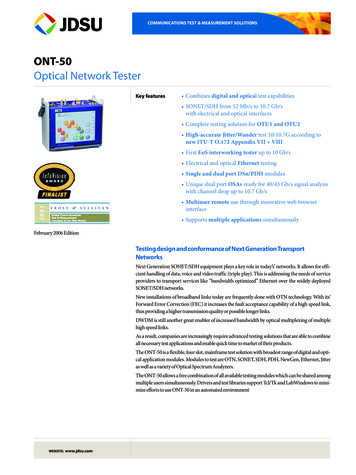
BC-600-PB7.2Connection to PROFIBUSSimple Connection for Tests During System ShutdownIf all bus stations provide D-sub connectors with an additional service socket,you can simply plug in the PROFIBUS Tester 4 at that socket (see figurebelow). If a D-sub connector does not provide a service socket, you can plugin the D-sub adapter cable underneath. The only thing you need to keep inmind is that you should never cascade more than two D-sub connectors (seepage 17).When using M12 connection technology, the M12 adapter cable is “looped”into the bus. It is essential to ensure proper termination at the beginning andend of the bus by using the terminating resistor provided with the M12 adapterset.Attention: All these simple connection types will divide the bus. Youtherefore need to shut down the PLC and all the devices connectedto the PROFIBUS; in other words, you need to shut down the wholeinstallation.Remote I/OPLCRemote I/ORemote I/OD-subConnection pointsM12Terminationat begin andend of bus!orFig. 13: Connection points at system shutdownSoftingPage 19
Connection to PROFIBUS7.3ManualConnection for Testing a Live BusTo test a live PROFIBUS with the PROFIBUS Tester 4 during operation,appropriate connection possibilities have to be provided. If no suitableconnection points are available in the existing installation, it is recommendedto install them during system shutdown. This will make future maintenancework much easier.Attention: When installing additional connection points, you divide thebus. Before doing so, you therefore need to shut down the PLC andall the devices connected to the PROFIBUS; in other words, you needto shut down the whole installation.Attention: For testing on live systems the optional D-sub adaptercable BC-600-PB-CB-DSUB-1 with reduced influence on busoperation is highly recommended! See page 9.Page 20 2013
BC-600-PB7.3.1Connection to PROFIBUSConnection via D-sub connector with service socketIf all bus stations provide D-sub connectors with an additional service socket,you can simply plug in the PROFIBUS Tester 4 at that socket (see figurebelow).PLCD-subRemote I/OMPI Operator PanelRemote I/OConnection pointsFig. 14: Connection points for the D-sub adapter cableSoftingPage 21
Connection to PROFIBUS7.3.2ManualDirect cable connectionTo test a live PROFIBUS, you will need additional D-sub service interface ofthe type BC-PBMB-PB-S (see page ection pointsFig. 15: Service interface provide connection points at direct cable connectionPage 22 2013
BC-600-PB7.3.3Connection to PROFIBUSConnection via M12 connectorTests on a live PROFIBUS are only allowed on bus segments providing D-subconnection technology. Only D-sub connectors with service socket can beused as connection points for the test tool. For this reason, tests can often onlybe performed at a bus end.PLCD-subRemote I/ORemote I/ORemote I/OConnection pointFig. 16: Connection points for the M12 adapter cable7.4Master Simulator and Topology ScanThe master simulator allows checking the bus cabling and the stationaddresses during installation and commissioning, when the PLC (master) isnot in operation yet. In addition, you can use this mode to check individual“suspicious” bus stations that have been disconnected from the bus.SoftingPage 23
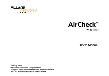
Connection to PROFIBUSManualThe topology scan determines the sequence and distances of all passive busstations (slaves). This feature requires correct bus cabling, a very good signalquality, and a connection point located directly at the beginning or end of thebus.Both features can only be used during shutdown of the installation. The D-subcable BC-600-PB-CB-DSUB-2 which is included in the standard scope ofsupply must be used. As long as communication is detected on the bus, i.e. atleast one device is an active master, the functions are disabled. If necessary,disconnect every single active device (PLC, MPI and, if necessary, diagnosticrepeaters) from the power supply or the bus. If an active device is at the end ofthe bus you want to test, its PROFIBUS connector needs to be unplugged andconnected directly to the PROFIBUS Tester 4. The bus termination in thedevice connector will then be powered by the PROFIBUS Tester 4.PLCMPI Operator PanelRemote I/ORemote I/ODisconnect from busw/oadaptorcableConnection pointsD-subD-sub cable „Standard“BC-600-PB-CB-DSUB-2Fig. 17: Connection points for topology scanPage 24 2013
BC-600-PBConnection to PROFIBUSAttention: Bus stations must only be disconnected from the powersupply or the bus during shutdown of the installation.Attention: The two functions can be started also when the PROFIBUSTester 4 is disconnected from the bus. If you then connect thePROFIBUS Tester 4 to a live bus despite the yellow bus status barindicated by the PC software, this can cause bus communicationproblems or a shutdown of the installation.7.4.1Special case: Active devices at both ends of the busOn the very rare occasion when there is an active device at each end of thebus, do the following:1. When using D-sub connection: Additionally switch on the terminating resistor in the D-subconnector of the last slave. The outgoing cable to the activedevice at the bus end has to be connected to the outgoingconnector (marked with “OUT”, an outgoing arrow, or “A2/B2”).Fig. 18: Checking the connection direction at the D-sub connector2. When using M12 connection: SoftingThe cable from the bus start or test tool has to be connected tothe incoming M12 connector of the last slave. A bus termination isrequired at the outgoing M12 connector of the last slave.Page 25
Display and Control in Stand-Alone Mode8ManualDisplay and Control in Stand-Alone ModeThe PROFIBUS Tester 4 always starts in stand-alone mode unless it is USBconnected to a PC or notebook. The readings are shown on the display. Youcan control the tool with the four function keys.When you establish a USB connection during stand-alone mode while a test isrunning, the test will be aborted and the tool will be reset (restart). The displaybriefly shows: “Changing operating mode – Please wait ”.8.1Main DisplayThe baud rate of a connected PROFIBUS network is detected and displayedautomatically:Fig. 19: Main display - example of a live PROFIBUS at 1.5 Mbit/sPage 26 2013
BC-600-PBDisplay and Control in Stand-Alone ModeThe PROFIBUS status is shown in line 2. The following displays are possible:3. The PROFIBUS is not connected: Display: “DP n/a”4. The PROFIBUS is connected, but no master is active: Display of the static RS485 bus voltage,e.g. “DP 1015 mV stat.”5. The PROFIBUS is connected and one or more masters are active: Display of the detected baud rate, e.g. “DP 1.5 Mbit/s”The status of the integrated master simulator is shown in line 3. The followingdisplays are possible:1. The master simulator is disabled: The display remains blank.2. The master simulator has been enabled manually (see page 36): Display: “M.Sim. ON”The only control on the main display is the down arrow key with which you canselect the individual functions.SoftingPage 27
Display and Control in Stand-Alone Mode8.2ManualOperating ConceptFig. 20: Display control with the four function keysPage 28 2013
BC-600-PB8.3Display and Control in Stand-Alone ModeFunctions8.3.1Live Status functionThe Live Status function very quickly gives you an overview of the bus status.Even transient disturbances during the test are reliably detected. Once youstart the function, the tool determines and continuously updates the status forthe segment and for each bus station.8.3.1.1Bus status summaryFig. 21: Live Status with bus status summaryLine 1 shows the overall bus status. It results from the substatus for buscommunication and the substatus for bus physics, which are displayed in lines2 and 3.Bus communication:1. “Error” 2.Bus stations were dropped or added during the testConfiguration errors or parameter errors occurred(the actual structure of modular slaves differs from theconfiguration stored in the PLC, or an incorrect GSD file wasused)„Warning“ Frame errors, retries or diagnostics occurred during the testOne or more bus stations have not been configured in the PLC3. „OK“ SoftingNo critical states or eventsPage 29
Display and Control in Stand-Alone ModeManualBus physics:1. “Error” 2.One or more bus stations failed to respond during the last physicaltest cycle„Warning“ 3.One or more quality indexes* are below the user-defined limitvalue (default: 2500)„OK“ All quality index* results are above the limit value* . See the “Interpretation of the signal quality test results” chapterin the PROFIBUS Diagnostics Suite manual.Page 30 2013
BC-600-PB8.3.1.2Display and Control in Stand-Alone ModeSegment status 1Fig. 22: Live Status with segment status 1To the right of “DP Segm.” in line 1, the display shows changes in the live list(added and dropped bus stations). The following displays are possible:1. The number of bus stations has not changed during the test: No display of live list changes2. One or more bus stations have been added during the test: “ ” display3. One or more bus stations have been dropped during the test: “-” display4. One or more bus stations have been added and one or more droppedduring the test: “ -” displayThe live list should usually not change when a PROFIBUS system is stable.In line 2, you see the number of masters (M) and slaves (S). For the slaves,the first figure indicates the number of slaves addressed by the master(s). Ifnot all slaves respond, the number of slaves that failed to respond is indicatedafter a “-” sign.Line 3 indicates the token rotation time. Note: The token rotation time does notnecessarily equal the bus cycle time.SoftingPage 31
Display and Control in Stand-Alone Mode8.3.1.3ManualSegment status 2Fig. 23: Live Status with segment status 2Line 1 is the same as for segment status 1.In line 2 you see, on the left, the number of retries on the entire segment and,on the right, the worst quality index of all bus stations.Line 3 shows, on the left, the number of frame errors on the entire segmentand, on the right, the best quality index of all bus stations.Page 32 2013
BC-600-PB8.3.1.4Display and Control in Stand-Alone ModeStation statusThis function displays the station status for each bus station, i.e. for all mastersand all slaves.Fig. 24: Live Status with station status of a masterFig. 25: Live Status with station status of a slaveThe PROFIBUS address of the bus station is displayed right after “DP#” on theleft of line 1. The letter in the middle indicates whether the device is a master(M) or slave (S). If the letter is enclosed in square brackets, the BC-600-PBwas able to determine the address of the PROFIBUS device to which it isconnected. In the above example, the test tool is connected to the device withthe address 11 (see Fehler! Verweisquelle konnte nicht gefundenwerden.). On the right, you see the live list changes (see page 31) for this busstation.Line 2 shows the number of retries on the left, and the worst quality index ofthis bus station on the right.Line 3 indicates the number of diagnostics on the left, and the best qualityindex of this bus station on the right.Note: The update rate for the live status substantially depends on the numberof bus stations and the signal quality.SoftingPage 33
Display and Control in Stand-Alone Mode8.3.2ManualQuick Test functionThe Quick Test allows full testing of bus physics and bus communication. Thetest data is stored in the tool. It can subsequently be imported by thePROFIBUS Diagnostics Suite software application.To start the function, choose one of 10 internal memory locations. The displayindicates if the selected memory location is allocated or free. If you select anallocated memory location, the previous test data will be overwritten.Fig. 26: Quick test completedThe duration of a Quick Test depends on the baud rate, the number of slavesand the current bus communication. It can take only a few seconds or up tothree minutes.On completion of the test, press the acknowledgment key to cancel the statusdisplay.Page 34 2013
BC-600-PB8.3.3Display and Control in Stand-Alone ModeTrend functionTrend logging is used for detecting rare or sporadic faults over a prolongedperiod of time. The function monitors both the bus physics and critical eventsin the bus communication. The PROFIBUS Tester 4 can automatically test thebus in stand-alone mode from within the control cabinet for up to 41 days. Thetest data is stored in the tool. It can subsequently be imported by thePROFIBUS Diagnostics Suite software application.Before you start the function, choose a test interval. When you select “Auto”the tool automatically determines the optimum interval. The Trend Test runsuntil manually stopped with the “x” key.Fig. 27: Trend running for 23 h and 52 min.The test is aborted automatically when the power supply is interrupted (all datalogged so far is retained in memory) or when the maximum logging time of 999hours and 59 minutes is reached.SoftingPage 35
Display and Control in Stand-Alone Mode8.3.4ManualMaster Simulator functionThe master simulator is disabled by default when you switch on the tool. Youcan only select a baud rate on the display and thus start the master simulator ifno other master is active.8.3.5Settings and help functionsThe following options are available: Settings/Delete all internal memory locations: Deletes all quick testsand trend recordings Settings/Current language: Toggles between English, German,French, Italian, Polish and Spanish (all w/o national specificcharacters) Settings/Limit signal quality: Sets the limit value in increments of 100(default: 2500) Settings/Time-out signal quality: Sets the time-out value in incrementsof 5 (default: 5 seconds) HW Information: Displays on two screens the firmware and FPGAversions and the date and time of the last factory calibration. Help: Briefly describes the functionality of the four function keys.Page 36 2013
BC-600-PB9Data Import into the PCData Import into the PCQuick Tests and Trend logs stored in the test tool can be imported into the PCsoftware. To do this, start the PROFIBUS Diagnostics Suite. If a PROFIBUSTester is connected to the PC via USB and contains stored test data, anadditional “Import Test Data from Tool” dialog box appears automatically.Fig. 28: Importing test dataFor ALL the stored data, you need to fully select the action to be performed,the network/project, and the test location to which you want to store the data.The default action “Import & Delete“ deletes the test data in the tool after theimport is complete. This frees the allocated memory locations for new tests.The imported Quick Tests and Trend logs are fully compatible with the testdata that can be acquired using the PC software.SoftingPage 37
Firmware UpdateManual10 Firmware UpdateFirmware updates are made available as required. They are provided with theupdates to the PC software (see page 16) and allow access to new orimproved functionality. How to update the firmware is described in detail in theseparate “PROFIBUS Diagnostics Suite – Getting Started” manual.Page 38 2013
BC-600-PBMaintenance and Servicing11 Maintenance and ServicingThe PROFIBUS Tester 4 i
software on your computer and select the PROFIBUS Tester and a network for testing in its user interface, the test tool switches to PC mode. The display shows: Fig. 10: Display at testing with PC software . While in PC mode, you can only display readings and operate the tool by using the control an