Transcription
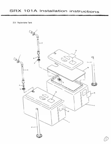
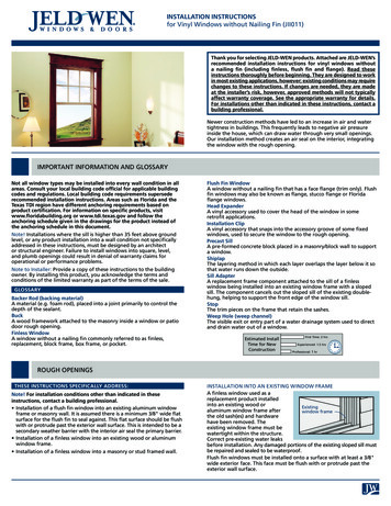
Installation InstructionsMUSTANG II IFS COMPLETE PARTS PACKAGEPlease read these instructions completely BEFOREstarting your installation!Your Southern Rods & Parts Mustang II IFS Parts Packagecontains the following items:1 pr) Upper Control Arms (2023)1) Upper Arm Bolt Kit (MP-001-A)1 pr) Lower Control Arms (2024)1 pr) Brake Rotors with Bearings & Seals1 pr) Brake Calipers with Pads1) Caliper Bolt Kit1 pr) Spindles (5556 or 2-5556)1) Spindle Nut Kit (HK-006)1 pr) Coil Springs (SPA8542) & Shocks (PRSSM400)1) Rack & Pinion with Tie Rod Ends1 pr) Rack BushingsYour Mustang II IFS Parts Package contains the parts listed above. Thebasic assembly for a Mustang II IFS is shown on the exploded view on thissheet. Most of the individual kits, such as the control arms, have their ownseparate instructions which are packaged in their boxes. Follow thoseinstructions for those parts. Begin the suspension component installationwith the upper and lower control arms using their instruction sheets. Placethe springs up into the spring pockets and bring the lower arms up to them.Using a floor jack under the lower ball joint (or an external springcompressor), compress the springs by raising the lower arms up intoposition. Install the shocks by placing the first washer and rubbermount on the shock stud and sliding them up thru the lower arms andinstall the long bolts thru the lower arms and shocks first. The shocks arethe top-out device and will hold the springs in place. As the lower arms areraised, attach the upper rubber mount, washer and nut on top of theshocks when they come through the upper shock mount cups. Install thespindles onto the lower ball joints and then install the upper ball joints intothem. Now install the rack and pinion assembly using the two 5/8” bolts,washers and lock nuts supplied with the crossmember. Install the tie rodends onto the rack and into the spindle arms. Estimate the alignment atthis point. Install the rotors and calipers next. You can now place thevehicle on the ground. Do not cut the springs to get to your ride height untilthe vehicle is finished and all the weight has settled the springs. Now is agood time to install your Steering Column and connect your steering.(Southern Rods and Parts stocks steering columns, u-joints, DD shaft,etc. to complete this.)
rubber
Installation InstructionsMUSTANG 2” DROPPED SPINDLESPlease read these instructions completely BEFORE startingyour installation!Begin installation of your Dropped Spindles by placing the Spindles on the lower controlarm ball joints and assemble ball joint nuts. Insert the upper control arm ball joints intoSpindles and assemble nuts. Install the tie rod ends into the Spindles next and assembletie rod ends and nuts. Now that the Spindles are being securely held in place, tighten allthe nuts and install the cotter pins. If you are using the factory dust shields, install themnow. A new upper hole must be drilled in the dust shield to line up with the upper hole inthe Spindle. Do not drill a new hole in the Spindle.Install the rotors next, installing new cotter pins in the spindle nuts. Install the calipersnext, using original hardware or new Grade-8 bolts . Loctite is a good idea, also.At this point, steer the Spindles from lock to lock with the suspension both up and down,checking the brake lines for adequate length. Make sure they are not pulled tight, oragainst anything. New, longer stainless steel lines may be required (Southern Rods pn#4778. When installing wheels, check the clearance at the lower ball joints, lower controlarm flanges and tie rod ends while again steering the Spindles from lock to lock. NOTE:If you are using stock control arms trimming of flanges on the outer edges of the lowercontrol arms around the ball joints may be necessary as the flanges may contact theinside of the brake rotor during suspension travel. Run the suspension up and down andobserve the clearance there. Tubular lower control arms are slimmer and have lowerprofile ball joints if more clearance is needed. Wheel spacers are another common itemwhen using any Dropped Spindles. Remember that even though it is a direct bolt-onpart, a Dropped Spindle is a different design spindle and compatibility of mating parts isthe responsibility of the installer.
Installation InstructionsLATE MUSTANG IFS POWER RACK & PINIONUPGRADEPlease read these instructions completely BEFOREstarting your installation!Your Southern Rods & Parts Power Rack & Pinioncontains the following items:1) Power Rack & Pinion2) Rack Spacers2) 5/8-11 x 4 1/2” BoltsThe rack & pinion supplied is a 1994 and later “V” style Ford Mustangunit. This rack can be used on any of our Front SuspensionCrossmembers that have the slotted rack mount on the passengerside. The kit is supplied with two 3/4” spacers* which must beinstalled between the rubber rack bushings and the rack mounts onthe crossmember. Use the longer 4 1/2” bolts supplied. See Figure 1.This power rack has a “V” style input shaft and uses the same tie rodends as the Mustang II rack. The high pressure fitting is the M14x1.5thread port which is toward the front of the rack, and the return fittingis M16x1.5 thread port that is at the rear, closest to the pinion inputshaft. See Figure 2. WARNING! Care must be taken that the hosesare hooked up correctly, since the braded hose adapters suppliedwith most hook-up kits convert both ports to a –6 hose size. If thehoses are incorrectly installed, the internal pressure will blow out theseals under the boots and cause leaking. Incorrect hose installationwill void the warranty, as the rackand pinion units are pressure tested at the rebuilder’s plant.Please read these instructions completely BEFOREstarting your installation!
are hooked up correctly, since the braded hose adapters supplied with most hook-up kits convert both ports to a –6 hose size. If the hoses are incorrectly installed, the internal pressure will blow out the