Transcription
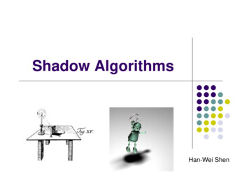
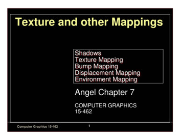
No Shadow Left Behind: Removing Objects and their Shadows usingApproximate Lighting and GeometryEdward Zhang1Ricardo Martin-Brualla2Janne Kontkanen21,2Brian Curless1University of Washington 2 GoogleApproximate Lighting& GeometryInput ImageObject RemovedObject to RemoveObject ReplacedFigure 1: We present a method to remove an object and its shadows from an image, to enable applications like home refurnishing. Ourmethod takes as input an image, approximate scene lighting and geometry, and an object mask, and generates a new version of the imagethat depicts the scene as if the object had not been present. This not only includes inpainting the occluded pixels, but removing any shadowscast by the object.AbstractRemoving objects from images is a challenging technicalproblem that is important for many applications, includingmixed reality. For believable results, the shadows that theobject casts should also be removed. Current inpaintingbased methods only remove the object itself, leaving shadows behind, or at best require specifying shadow regions toinpaint. We introduce a deep learning pipeline for removing a shadow along with its caster. We leverage rough scenemodels in order to remove a wide variety of shadows (hardor soft, dark or subtle, large or thin) from surfaces with awide variety of textures. We train our pipeline on synthetically rendered data, and show qualitative and quantitativeresults on both synthetic and real scenes.1. IntroductionMixed reality aims to seamlessly combine the virtual andthe real. As one example, imagine an interior design appthat lets you try out new furniture. Most previous work inaugmented reality focuses on inserting virtual objects – forinstance, putting a virtual sofa into your living room. Thescope of these applications can be greatly expanded by alsoenabling manipulation of real-world objects – imagine removing the futon that you intend to replace with the sofa,and moving a coffee table over to make more room for it.Previous work on object removal has focused solely onthe inpainting problem – that is, replacing the pixels previously occupied by the removed object. However, for realistic results, we need to remove the sofa and the shadows itcasts on the wall and the floor, as well as the reflection onthe hardwood floor. For the purposes of this paper, we focusonly on the shadow removal problem.Existing inpainting-based approaches for object removaleither ignore the shadows of the object, or mark them tobe inpainted as well. However, very large shadows mayleave little image content to copy pixels from. Furthermore,this approach requires segmenting out the object’s shadowin addition to the object itself – a difficult task, as varyinglighting conditions can cause multiple shadows, very softshadows, or overlapping shadows, and a surface texture mayhave dark regions that could be mistaken for shadows.Inspired by Debevec’s [9] work in virtual insertion of objects in scenes, we use a scene proxy to help determine thevisual effects of a scene manipulation. Debevec performsthe scene edit on the proxy model, and renders the proxypre- and post-edit. The pixelwise difference between the116397
two renderings, which for object insertion contains shadows and reflections of the virtual objects, is then applied tothe input image to produce the final output. This method isknown as differential rendering. However, it is not practicalto solve the shadow removal problem by applying the pixelwise difference directly, since the shadows in the proxymodel are only a rough estimate of the real shadows. Toaccount for this, we propose a neural network based systemfor more general differential rendering for object removal.An obvious question is, how do we obtain an editablescene proxy? One could use a depth camera, monoculardepth estimation [13, 14], or a global model obtained as aside effect of localization [8] for the geometry. For lighting, the possibilities include a mirror sphere, panorama, orlearning based methods [22, 29, 30]. In this paper we usedepth maps captured by an affordable depth sensor and a360 panorama, but the method is not fundamentally limited to proxies obtained by these devices, nor do the proxymodels need to be very accurate. Our proxy mesh is generated from a single depth map, thus modeling only frontfacing surfaces, and our lighting is captured as an uncalibrated HDR environment map with only very rough alignment. We show that even this constrained and incompleteproxy provides enough information to generate plausible removal results across a wide range of conditions.In this paper we present a method for removing an object and its shadows from an input image, given a roughmodel of the scene and the mask of the object. Our systemis more accurate and produces fewer visual artifacts thana general image-to-image translation system or an inpainting method, even when the inpainting method is given theshadow regions it should replace.2. Related Work2.1. Scene EditingEditing scenes in a visually realistic manner has longbeen an area of interest in the graphics community. Mostof this work has focused on virtual object insertion. Classical methods construct an approximate model of the sceneto help perform these edits, ranging from Debevec’s earlywork [9], which assumes lighting and geometry were directly captured, to more recent work by Karsch et al. [19],which infers geometry, albedo, and lighting from a singleimage. Beyond simply inserting objects, Kholgade et al.[20] are able to move an object around, although they assume that a high-quality 3D model of the object is available.Research on object removal has traditionally focused onthe inpainting problem, ranging from classical techniquessuch as PatchMatch [1] to recent learning-based techniquessuch as DeepFill [36] and HiFill [35]. These methods donot consider lighting interactions between the removed object and the rest of the scene; thus when removing the ob-ject by inpainting, the user-specified mask must be extendedto include the object’s shadow. Recent work by Wang etal. [34] employs deep networks to associate shadows withtheir casters; however, their instance segmentation approachproduces hard boundaries and does not work for soft shadows. Zhang et al. [37] remove objects from indoor scenesby constructing a full scene model and rendering it withoutthe objects, eliminating the need for inpainting and shadowidentification; however, their approach requires an involvedcapture process and is limited by the expressivity of theirparametric scene model.The issue of the limited range of scene models is inherent to all of the methods that rely on such models for sceneediting. Most works (e.g. Kholgade [20]) use Debevec’sdifferential rendering method to account for differences between the model and the real scene. Recent approaches forneural rerendering use image-to-image translation to mapfrom the domain of the approximate model to a realisticresult [23, 24]. Philip et al. [26] introduced a method forrelighting outdoor photographs that also leverages proxyscene models. Their system is designed to handle globalchanges in illumination, like changing the position of thesun; furthermore they rely heavily on shadow masks thatcannot handle complex environment lighting. Instead, wefocus on local changes informed by the differences in theappearance of the proxy scene, based on an intrinsic decomposition that can handle multiple soft shadows.2.2. Shadow RemovalRemoving shadows from images is another problem thathas a long history. Note that the goal of these works is toremove all shadows from an image, while our goal is to isolate and remove the shadow(s) of a single object. To helpapproach this more challenging task, we assume the presence of a rough scene proxy.Classical intrinsic image decomposition methods are designed with various priors, typically specializing in lowfrequency lighting and thus handling soft shadows well[3, 2, 5, 15]. Another set of methods specialize in hardshadows and classify gradients as shading or texture [4, 31];however, these methods break down when shadow receivershave complex texture. Finlayson et al. [11] place assumptions on light source chromaticity, allowing for removal ofboth soft and hard shadows at the expense of generality.Recent methods use deep networks to perform shadowdetection and removal, starting with work by Qu et al. [27].Advances such as adversarial losses [33, 10], a two-stagedetection-then-removal scheme [16], or lighting inference[21] have resulted in great improvements on shadow removal on the common ISTD [33] and SRD [27] datasets.However, these datasets only contain hard shadows produced from outdoor lighting. Our system is trained to handle much more diversity in lighting conditions.126398
3. Training Datawhile keeping the same orientation.To better understand our architecture and losses, we firstdiscuss our training data. Our system is trained on a synthetic dataset, which allows us to greatly expand the diversity of lighting and receiver textures compared to priordatasets. Furthermore, it also allows us to generate groundtruth intermediates such as intrinsic decompositions, whichare crucial to our system.To generate training data, we set up 60000 input sceneswith randomly generated geometry, textures, lighting, andcamera parameters. These scenes are rendered using PBRT[25] to produce images of resolution 512 512. The datasetexhibits a wide variety of shadow casters (e.g large objects,thin structures, and objects with unusual silhouettes) andlighting conditions (hard or soft shadows, very dark or verysubtle shadows, multiple shadows). Some examples areshown in Figures 3-4 and in the supplementary material.3.2. Image Generation3.1. Scene GenerationGeometry: Our generated scenes consist of a groundplane supporting six to seven objects randomly selectedfrom the 50000 3D models in the ShapeNet [6] dataset,which include a variety of object classes ranging from furniture and tableware to cars and airplanes. These objectsare arranged in a ring around a central object, and are scaledsuch that the bounding boxes are nonintersecting. Each object is translated such that it lies entirely on top of the plane,and has a random rotation around its up axis. The groundplane is large enough to support all the shadow casters, plusan additional margin for shadows to potentially fall upon.Materials: The supporting plane is given a matte material, and is assigned a random texture (e.g. carpet, wood,stone, tile). Existing texture datasets are too small (e.g. Brodatz [32]) or have textures which are nonuniform (e.g. Describable Textures Dataset [7]). We use a manually curatedtexture dataset of 8000 images from Google Image Searchresults. ShapeNet objects come with prespecified materials.Lighting: We illuminate each scene by one of the 400HDRI maps at HDRI Haven1 , randomly rotated around theup axis. To supplement the lighting, we add a point lightwith random intensity (setting the maximum to the peak intensity of the HDRI map) randomly placed between a minimum and maximum distance from the center of the plane,in the upper hemisphere.Camera: We define a range of camera positions lyingon an upper hemisphere of fixed radius in terms of spherical coordinates facing the center of the scene. We allow theazimuthal angle to vary freely, but set a minimum and maximum elevation angle (as people rarely observe scenes fromdirectly overhead or from very low angles). After selectingan initial camera pose we then perturb the camera’s position1 https://hdrihaven.com/Using PBRT, we render three RGB images of each scene:T̂ , the ground plane alone with diffuse texture; L̂, the complete scene with the plane material replaced by a diffusewhite material; and L̂′ , the scene with the central object removed with the same alteration to the plane material. Theseimages comprise the ground truth intrinsic decomposition’stexture and lighting, and the lighting post-object-removal.Note that these images do not form a true intrinsic decomposition of the entire scene, only of the receiving plane. Wealso render the ground plane alone with no texture to capture its unshadowed appearance Lr .Next, we render depth maps D, D′ of the unedited andtarget scenes, as well as a depth map Dr of solely theground plane receiving shadows, all using the same camerapose as the RGB images. From these we compute a pixelmask of the object to be removed Mo I(D′ D) whichis 1 where the object is and 0 everywhere else. We also compute a receiver mask Mr I(Dr 6 , Dr D) which is1 for pixels lying on the ground plane in the unedited sceneand 0 everywhere else.To allow for further augmentation, we do not raytrace theinput and output images I, Iˆ′ ; instead we compute them attrain time from the decomposition: I (Mr T̂ (1 Mr ))L̂and Iˆ′ (Mr′ T̂ (1 Mr′ ))L̂′ . This allows us to modifythe hue, saturation, and brightness of texture and lighting attrain time. Note that we forgo indirect bounce lighting inour synthetic data to enable this augmentation, as indirectillumination depends on the surface reflectance, i.e. texture.To mimic real capture, we add noise to the depth mapof the unedited scene and construct a triangle mesh fromthe depth map as our approximate geometry, replacing theground plane vertices with a best-fit plane (which continuesbehind the removed object). To form the target proxy geometry, we delete the depth pixels occupied by the removedobject. This scene is lit with a perturbed version of the inputlighting: we jitter the point light’s position, color, and intensity, apply a random nonlinear scale to the HDRI map, andrandomly rotate the HDRI map by a small amount. All materials are set to a diffuse white; note that we do not modelthe surface reflectance (texture) of the plane as it would imply already knowing the intrinsic decomposition. Rendering these elements produces P, P ′ , respectively the imagesof the unedited and target scene proxy.3.3. NormalizationOur intrinsic decomposition has a scale ambiguity,which we resolve by normalizing the ground truth lightingL̂, L̂′ at train time, expecting that the network will producenormalized lighting images. Specifically, we apply a perchannel scale to both L̂, L̂′ such that the maximum pixel316399
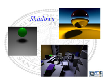
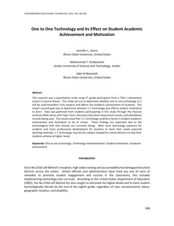
Figure 2: Overview of our approach. We take an input image, a mask of the object to remove, and renderings of a rough scene modelwith and without the object. We first decompose the input image into texture and lighting. We then remove the object’s shadows from thelighting image. We inpaint the object mask region separately in both texture and lighting before recompositing to get our final result.value on the receiver across both images is (1, 1, 1). Similarly, we compute a normalization factor for images of thescene proxy P, P ′ (which are just approximations of L̂, L̂′ ).This occurs at both test and train time.For both train and test we scale the images in the inputdomain (i.e. I and Iˆ′ ) to have a channelwise mean pixelvalue of 0.5 on the ground plane.form where the remaining shadows in the scene shouldcontinue behind the removed object. For texture inpainting, we use an off-the-shelf inpainting method.Inpainting the decomposed texture, rather than the final composite, prevents the inpainting method fromhallucinating its own shadows. Lastly, we recompose the lighting and texture imagesback together to produce our final result.4. MethodOur pipeline consists of a series of convolutional neural networks (we use a single U-Net [28] for each component), with an inpainting stage to produce our final results.A visual overview can be seen in Figure 2. Our systemtakes as inputs the original image, a rendering of the approximate scene model before object removal (referred toas the shadow proxy), a rendering of the scene model afterobject removal (target proxy), and binary masks denotingthe object to remove and the receiving surface from whichto remove shadows. An overview of our pipeline follows: The intrinsic decomposition subsystem separates theinput image into texture and lighting, guided by theshadow proxy. Following existing works [16] onshadow removal, we use a two-stage scheme with aninitial shadow segmentation network. The shadow removal network removes the shadowof the removed object from the decomposed lighting,aided by the shadow proxy and target proxy images.We define I, I ′ as the input and output images, respectively. P, P ′ are the shadow proxy and target proxy. Theintrinsic decomposition is denoted by I LT, I ′ L′ T ′with L, L′ being the lighting images and T, T ′ being the reflectance (texture) images. Mo is a binary mask which is1 for pixels lying on the object to be removed and 0 elsewhere. Mr is a binary receiver mask which is 1 for pixelslying on the local scene receiving the shadows, and 0 forpixels elsewhere. This restricts the network to operate ona surface with a single texture, as otherwise the intrinsicdecomposition frequently mislabels shadows as changes inreflectance if the surface reflectance can vary arbitrarily.RGB images are processed in the log domain, turningthe intrinsic decomposition I LT into a sum log(I) log(L) log(T ) that is more naturally represented byCNNs. Using synthetic training data enables full supervision of each subnetwork’s intermediate outputs.Shadow Segmentation: This subnetwork produces a 1channel soft segmentation in [0, 1], where 1 is full shadow. The inpainting subsystem separately inpaints thelighting and texture behind the removed object. Ourlearned lighting inpainting uses the target proxy to in-S fSS (log(I), log(P ), Mr )(1)Intrinsic Decomposition: This subnetwork decomposes146400
the input image into 3-channel lighting L and texture T .L, T exp(fID (log(I), log(P ), S, Mr ))(2)Shadow Removal: This subnetwork removes theshadow of the object from the predicted lighting image, producing one 3-channel output, the masked target lighting.L′r exp(fSR ( log(I), log(T ), log(L),log(P ), log(P ′ ), S, Mr , Mo ))map, since any object will occlude some part of the distantillumination. To supervise this stage we therefore examinethe ratio of pixel values between the ground truth lightingwith all the objects compared to the ground truth lighting ofonly the receiving surface. A shadow is defined as any pixelwhere this ratio is is less than the median ratio on any of thethree color channels using a soft threshold:(3)Ŝ max σmedian(L̂/Lr ) L̂/Lrα!!(8)Lighting Inpainting: This subnetwork fills in the predicted lighting L′r behind the removed object, continuingshadows cast by other objects through the mask if necessary. The target lighting L′ is then the composite of theinpainted lighting and the masked target lighting.The shadow segmentation subnetwork is supervised bya class-balanced binary cross entropy term as well as a losson the gradients of the shadow segmentation:L′o exp(fLI (log(L′r ), log(P ′ ), Mo ))ESS λS ES λ S E S′L (1 Mo )L′r Mo L′o(4)(5)Texture Inpainting: We inpaint the texture image usingan inpainting operator g(T, Mo ), synthesizing the pixels ofT in the hole region specified by the mask image Mo . Forour experiments we used HiFill [35] for g(T, Mo ), trainedon the Places2 dataset [40].T ′ g(T, Mo )(6)Final Composite: The previous stages predicted the appearance of the receiver within the target receiver maskMr′ Mr Mo . We composite the remaining pixels fromthe original image, consisting of unaffected surfaces beyondthe local scene and other objects within the local scene.I ′ Mr′ T ′ L′ (1 Mr′ )I(7)ES Ŝ 1 (1 Ŝ) log(1 S) 1 Ŝ 1E S S Ŝ 2(10)(11)Intrinsic Decomposition: The intrinsic decompositionloss function is the most involved of our losses. The effectsof each term, as well as comparisons to existing works inintrinsic decomposition and shadow removal, are shown inthe supplementary material.EID λLT ELT λexcl Eexcl λI EI λ L E L(12)For the data term, a multiscale loss on the predicted lighting and texture images was vital to ensure the model wouldwork well on high-contrast textures.4.1. TrainingEach subnetwork is independently trained with theAdam optimizer for 60 epochs on 60000 training scenes,with ground truth intermediates substituted for the outputsof earlier subnetworks. We then train the whole system endto-end for 60 epochs. The system was implemented in Tensorflow and trained on four Tesla V100 GPUs with a batchsize of 16. The learning rate was 10 4 decaying by 0.5 every 10 epochs.Our loss functions are described below. For all networksexcept the lighting inpainting network, the inputs to thelosses are masked with Mr to only apply to pixels lyingon the receiver. For brevity we assume that the norm flattens across input channels and image dimensions. We denote a ground truth supervision image with a hat, so that theground truth intrinsic decomposition is L̂, T̂ , ground truthoutput image is Iˆ′ , and so on.Shadow Segmentation: It is difficult to define a groundtruth for what constitutes a shadow in a scene lit by an HDRI Ŝ log(S)(9)ELT P (L, L̂) P (T, T̂ )(13)where P (X, X̂) is an L2 loss on a Gaussian pyramid decomposition of the images X, X̂.To ensure a clean decomposition, we impose the exclusion losses of Zhang et al. [39] on the predicted lighting andtexture images, which in essence constructs 0-to-1-valuededge maps at multiple scales, and penalizes edges lying atthe same location in the two decomposed images.Eexcl i 3X4i Ψ(T i, L i) (14)i 0where X n denotes image X downsampled bilinearlyby a factor of 2n , and Ψ is as defined by Zhang et al.We also have an L1 loss on the two decomposed imagesrecomposing into the input image.EI I LT 1516401(15)
No-opPatchMatchHiFillPatchMatch ShadowsHiFill ShadowsPix2Pix (all)Pix2Pix (receiver)Pix2Pix Proxy (receiver) Intrinsic Decomposition Shadow Segmentation Lighting Inpainting 200.08020.03620.02460.0248SyntheticShadow 660.08820.07130.0712Inpaint 03650.25020.10910.08720.06180.03400.0340RealShadow 870.08430.06310.0616Inpaint 530.10550.10400.0983Table 1: Comparison of error rates for various shadow removal methodsFinally, we impose a sparse gradient prior on L to discourage textural details from leaking into the lighting.E L L 1(16)Shadow Removal and Lighting Inpainting: As withthe intrinsic decomposition, we apply a multiscale loss onthe predicted lighting after shadow removal and inpainting.EL′ λL′ P (L′ , L̂′ )(17)′Note that because L is a composite of the results ofthe shadow removal and lighting inpainting networks, theshadow removal network is only penalized for pixels lyingon the receiver in the original input image while the lighting inpainting network is only penalized for pixels withinthe mask of the removed object.We also add a recomposition loss on the final output.EI ′ λI ′ Iˆ′ L′ T ′ 1(18)5. ResultsWe evaluate our work both qualitatively and quantitatively on 5000 synthetic test scenes, generated the same wayas our training data, and 14 real scenes captured manually,which include ground truth object removal results.Commonly used quantitative metrics such as perceptuallosses [38, 18] or the RMSE, computed across the entireimage, are poor representations of the quality of shadowremoval results. A perceptually negligible color cast produced by a deep network across the entire image has an outsized effect on these metrics. To better represent the performance of various systems, we analyze accuracy in targetedregions of the image using a weighted RMSE. In additionto the RMSE across the entire image, we report the ShadowRMSE, which is computed across pixels within the groundtruth binary shadow mask Ŝ. We also report the RMSEwithin the removed object’s pixels to separately evaluate inpainting performance.5.1. Test DataThe proxy geometry and images for real scenes werecaptured using the Kinect v2 mounted on a tripod. Wecaptured three RGBD frames for each scene: I the complete scene, Iˆ′ the target image with one or more objects removed, and a bare scene with all objects removed. The approximate lighting was captured using a Ricoh Theta S 360camera with 5 exposures for HDR placed approximately inthe center of the scene, roughly pointed at the Kinect.We median-filtered the depth images to remove noise.We then computed the best-fit plane for the input depth image using RANSAC [12], and computed the receiver maskMr from pixels approximately lying on the plane. In thiswork we manually specified the object masks Mo ; real applications would use an automatic segmentation method.To compute the proxy geometry, we formed a trianglemesh from the depth map as we did with the synthetic data;however for cleaner shadows we replaced the vertices corresponding to the ground plane with a fitted plane. This geometry was then rendered with the captured HDR environmentlighting to produce P, P ′ . As we did not have ground truthintrinsic decompositions, we used the difference between Iand Iˆ′ instead of L̂ and L̂′ to produce the shadow mask Ŝused in the Shadow RMSE metric.5.2. End-to-End ComparisonsMost existing works on object removal do not focuson removing shadows cast by the object. We compare totwo general approaches as baselines: pure inpainting andgeneric image-to-image translation. We also include thenumerical error of the “no-op” procedure, which does nottransform the input at all. Quantitative results are shownin Table 1 and qualitative results in Figure 3, exhibitingvarying lighting conditions (multiple overlapping shadows,soft and hard shadows, high and low contrast shadows) andbackground textures in both synthetic and real test scenes.We compute the inpainting baselines using two methods:the classical nonparametric PatchMatch [1], and a recent616402
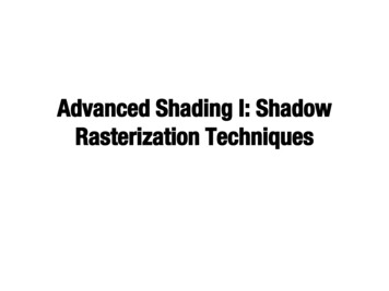
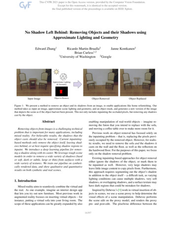
Ground TruthPix2Pix ProxyHiFill ShadowsOurse. Real 3d. Real 2c. Real 1b. Synthetic 2a. Synthetic 1Input ImageFigure 3: We compare our system to two object removal baselines on both synthetic and real test images. The first baseline is an image-toimage translation network based on Pix2Pix [17] which is supplied with our renderings of the proxy scene. The second baseline is HiFill[35], a state-of-the-art inpainting method, that inpaints both the removed object and an explicitly specified shadow mask.learning-based approach HiFill [35]. For both baselines, weinclude quantitative results both for a naive hole-fill, wherethe object’s shadows are not handled at all, as well as foran inpainting mask which includes the object’s shadows. InFigure 3 we show the results of HiFill inpainting when provided the ground truth shadow region. With this extra information, inpainting approaches work well for simple textures(3a,3c), but often hallucinate shadows within the inpaintedregion (3b). They also fail to take advantage of texture detail inside the shadow region, and the resulting artifacts arecompounded when the region to inpaint is large (3d). Notethat, compared to our method, these inpainting baselines donot use the proxy renderings.For our image-to-image translation baseline, we use thewell-known Pix2Pix method [17]. We compare againstthree variants of this baseline: one trained to predict the en-tire output image I ′ from the input I and object mask Mo ;one trained to predict only the appearance of the receivingsurface (using HiFill to inpaint the object region); and onetrained to predict only the appearance of the receiver butsupplied with our proxy scene renderings P, P ′ in additionto the input image and object mask. We show the results ofthis last version in Figure 3. The method fails to accuratelyidentify the extents of shadows (3c,3e) and their intensities(3a) and generalizes poorly to complex textures (3b,3d).5.3. Validating our ArchitectureWe show the importance of each step of our pipeline,starting with a single network to perform our generalizeddifferential rendering task and adding in each componentone by one. The results are shown in Figure 4 and the bottom rows of Table 1. We start with a single Pix2pix U-Net176403
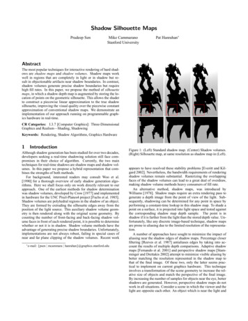
(a) Input(b) Ground Truth(c) Pix2pix (e.g. U-net)(d) Intrinsic Decomp.(e) Shadow Segmentation(f) Lighting InpaintingFigure 4: This synthetic example (a) shows the importance of each component of our system. The ground truth removal is shown in (b). Asingle U-net (c) hallucinates shadows in the inpainted region (red) and misidentifies shadows (green) with high-contrast textures. Addingin a texture decomposition subnetwork significantly improves the inpainting (d); however the edges of the shadows are still faintly visible(green). The shadow segmentation subnetwork eliminates these shadow ghosts (e). Some final artifacts visible within the silhouette of theremoved object are fixed with our lighting inpainting network (f).generator, that given all our inputs, predicts the output image excluding the pixels under the object mask, which areinpainted using HiFill (Figure 4c). The most obvious artifacts are within the inpainted region, where the inpainting method frequently fills in shadow pixels; this methodalso frequently misidentifies shadows, especially in highcontrast textures. We then introduce a separate intrinsic decomposition network, and allow the shadow removal network to work only on the resulting lighting image (Figure 4d); This system sometimes fails to remove hard orhigh-contrast shadows. Adding a shadow segmentation network (Figure 4e) makes decompositions of hard shadowsmuch cleaner. Finally, we introduce a lighting inpaintingnetwork (Figure 4f), as the shadow removal network alonehas trouble continuing shadows behind the object and sometimes leaves visible artifacts in the hole region.Figure 5: Input images (left) virtually refurnished (righ
Recent methods use deep networks to perform shadow detection and removal, starting with work by Qu et al. [27]. Advances such as adversarial losses [33, 10], a two-stage detection-then-removal scheme [16], or lighting inference [21] have resulted in great improvements on shadow