Transcription
Enterprise Networking SolutionsEnterprise Extender onz/OS Communications Server:SNA Hints and TipsSam Reynoldssamr@us.ibm.comAugust 4, 2014SHARE 2014 Summer Technical ConferenceSession 15513
Enterprise Network SolutionsAgendaHPRSubareaEEq SNA: Dead or Alive?APPNq Modernizing SNAq Enterprise Extender Recommendationsq Diagnostic Toolsq State of SNAq References402
Enterprise Network SolutionsSNA: Dead or Alive?"This report of my death was an exaggeration."Mark Twain, 1897SNA, 2014 SNA Applications:Over a trillion lines of customer written application code based on CICS,IMS, and DB2 A large percentage (a majority?) of all business data is still accessed via SNA applications Numerous market factors including the continued convergence of enterprise networks ontoIP technologies, and the withdrawal of the venerable 3745 from marketing, have led to avery rapid adoption of Enterprise Extender as a key component of SNA application accessstrategy amongst the IBM customer set. There have been multiple EE user experience presentations at SHARE conferences, byorganizations such as Bank of America, Finanz Informatik, iT-Austria, State Farm, and theSocial Security Administration3
Enterprise Network SolutionsSNA: A Little History SNA developed and distributed by IBM Specifications have been provided so that a large number of othervendors also provide products that implement SNA 1974 - SNA Announced Systems Network Architecture SNA is an architecture defining protocols such as: Link Protocols Node Intercommunication Protocols Application Protocols VTAM is the mainframe and NCP is the front-end SNA product VTAM runs on MVS, VM, and VSE VTAM and TCP/IP for MVS were combined into a single product(Communications Server) in 1996 NCP (Network Control Program) originally ran on a hardware front-endcontroller, such as the 3745. It can also run on a 37xx-emulator knownas the Communications Controller for Linux (CCL).4
Enterprise Network SolutionsSNA History: The Road to Enterprise Extender In the beginning, there was hierarchical SNA: VTAM, NCP, subareas, SSCPs, VRs, ERs,SNI. In the late 1980's, Advanced Peer-to-Peer Networking (APPN) began to emerge, firstappearing on the System 36 and AS/400, and by the early 90's on PCs via NS/2 (laterCM/2). APPN first appeared on the mainframe with VTAM V4R1 in 1993, although LEN ("APPNwithout a brain") was supported in V3R4 of VTAM. The first support for High Performance Routing (HPR) was introduced in VTAM V4R3 in1995. Support followed for the 22xx router, the Nways 950, PCs via CS/2, and Ciscorouters via the SNASw feature. Other platforms would follow over time. Enterprise Extender was first shipped on the mainframe with OS/390 V2R7 in early 1999(and was simultaneously made available on V2R6 via PTF). Enterprise Extender has now been implemented by numerous customers, and continuesto evolve, with enhancements in each z/OS release, including V2R1, which shipped lastyear.
Enterprise Network SolutionsModernizing SNA6
Enterprise Network SolutionsSNA modernization is about preserving SNA applications, not replacing them Analysts estimate that 200 billion lines of COBOL code exist today 5 billion lines are added each year Similar inventory of PL/I code The typical mainframe customer has: 30M lines of COBOL code Worth 600M Automating 100,000 business processes Any mainframe customer Banking, Insurance, Government, Manufacturing, Travel andTransportation, Distribution and Retail, Media and Utilities,Healthcare Industries A majority (70-80% according to some studies) of these existingapplications are terminal-access basedModernizing SNAis not about rewriting orthrowing awaySNA applications.It is aboutpreserving coreSNA businessapplications in anIP-based networkinfrastructure andit is aboutenabling re-use ofthoseapplications innew end-userenvironments inan applicationtransparentmanner.
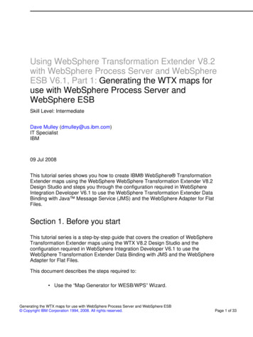
Enterprise Network SolutionsSNA networks and SNA applications in 2014 and beyond - what are thequestions that need to be asked?Corporation AChannelattachedSNAgatewayVTAM(z/OS, z/VSE, z/VM)Business partnersVTAM(z/OS, z/VSE, z/VM)IBM3745/46z/TPFIBM3745/46NCPVTAMNCP SNA NetworkInterconnect )SNAapplicationgatewaySNA Devicesuch as ATM3270APPN peer nodesTN3270 clientsIP or SNANetworkSNA Devicesuch as 3174,3278, 328xRe-write everything toIP-based ATSNCPboundarynodesHow do I modernize my SNA environment and maintain reliable andcost-efficient access to mainframe core SNA business applicationsand business partners with an aging SNA networking infrastructure?
Enterprise Network SolutionsWhat do we want to remove and what do we want to preserve?Branch Workstation or ServerData Center MainframeThis iswhat wewant topreserveSNA ApplicationMiddleware, such as CICS,IMS, MQ, DB2, etc.SNA programminginterfaces, such as CPI-CSNA ApplicationMiddleware, such asPCOM, MQ, CICS-GW, etc.SNA programminginterfaces, such as CPI-CSNA protocol stack, suchas VTAMSNA DLCAttachmentSNA applications andmiddleware do not depend onSNA networking hardware; theydepend on SNA programminginterfaces.Removing your old SNA networkinginfrastructure hardware and SNAbased wide area network does notmean you have to remove yourSNA applications!SNA protocol stack, such as PCOM, CSWindows, CS/2, CS Linux, CS/AIX, MS HIS,etc.This is what wewant to 221xSNANetworkSNA DLCAttachmentSNA modernizationtechnologies include: Enterprise Extender TN3270 Remote API CCL
Enterprise Network SolutionsWhat is Enterprise Extender? Allows use of IP network forSNA sessions EE allows enablement of IPapplications andconvergence on a singlenetwork transport whilepreserving SNA applicationand endpoint investment. EE is APPN HPR routing overan IP network To the IP network, EE looks like aUDP application To the APPN network, EE looks likean HPR link
Enterprise Network SolutionsEnterprise Extender characteristics The SNA traffic is sent as UDP datagrams over the IP network, each EE endpoint using 5UDP port numbers Firewalls can be an issue, especially between business partners! EE can be implemented on the SNA application hosts, or on APPN nodes that act as EEgateways! Complete APPN/EE nodes include z/OS, CS/Linux, CS/AIX, and CS/Windows Some EE nodes implement an EE-DLC connectivity function without being APPN network node capable examples include Microsoft's Host Integration Server which can only be an end node, and Cisco SNASwitch which can only be a Branch Extender node! Since EE is HPR over IP, EE traffic inherits all the APPN/HPR characteristics includingnon-disruptive path switch! EE traffic can be secured using IPSec But not with SSL/TLS - SSL/TLS is TCP only! Business partner connectivity through EE/EBN (z/OS only)
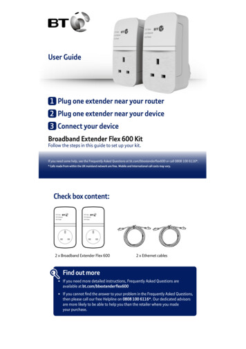
Enterprise Network SolutionsSubarea SNA to Enterprise ExtenderNETBNETANETBVTAM2VTAM4NETAVTAM2ENSA 2SA 2VTAM1VTAM3NCP2SA 3SA 1SA 1VTAM4NNEBNVTAM1NNEBNEEVTAM3NNSA 1OSA-LSASNINCP1NCP1NETCSA 4SA 4NETCSNA LANVTAM5VTAM5SA 2SA 2Peripheralnodes (PUType 2.0)NCP3EEEESNI.NCP3SA 1Cisco SNASwor Distributed CSSA 1DependentLUSubarea SNADependentLUEnterprise ExtenderSubarea (FID4) connectionsEnterprise Extender logical links12
Enterprise Network SolutionsEnterprise ExtenderRecommendations13
Enterprise Network SolutionsEE Recommendations #1 problem in bringing up EE connections: Any underlying firewall mustallow the transport of UDP ports12000-12004 (possibly limited toknown EE endpoint addresses)Firewall issues.UDP Port 12000F!I!R!E!W!A!L!L Configure APPN Link Characteristics TGPs for EE provided with VTAM - Customization of link speed is recommended Consider lengthening the EE LDLC timer parameters (LIVTIME, SRQTIME,SRQRETRY). It is recommended that the LDLC timer parameters be adjusted on both ends of the connection. Lengthen HPR path switch timers (HPRPST) as necessary to ensure that all four timersare longer than the LDLC timeout interval. This will ensure that RTP pipes stay in path switch long enough during IP network instability toallow the EE link to inop, and thereby allow another path to be selected. If multiple LDLC parameter sets are in use (by coding different LIVTIME, SRQTIME, andSRQTIME values on different XCA GROUPs), then the HPRPST values should be adjustedrelative to the longest of the LDLC timeout intervals.14
Enterprise Network SolutionsEE Recommendations . Define all of your EE connection networks on GROUP statements, and not on the XCAPORT. This will provide more consistent definitions as your connection networksexpand in the future, and allowsDEMOXCA VBUILD TYPE XCAyou to utilize GROUP-basedDEMOPORT PORTMEDIUM HPRIP*configuration options.DEMOGPGROUP DIAL YES,CALL INOUT,XAUTOGEN (5,EV4,P),DYNPU YES,ISTATUS ACTIVE Having ********************************* EXAMPLE VRN*definitions also enables *************************DEMOVRN GROUP DIAL YES,CALL INOUT,VNNAME NETA.LVRN,Xflexible and less disruptiveAUTOGEN (5,LV01,P),DYNPU YES,VNTYPE LOCAL,XHOSTNAME TUVIPA2.AREA51.SVT390.COM,Xupdating of the EE XCAISTATUS INACTIVE,TGP GIGENETdefinitions via theVARY ACT,UPDATE ALL command Leave the IPPORT operand at its default of 12000. If you change it, you must change iton all EE platforms that you connect to, and some do not support such a change. If defining an EE Connection Network over an IP network which employs NetworkAddress Translation (NAT), you must define the virtual routing node's addressabilityusing the HOSTNAME operand (not the IPADDR operand).15
Enterprise Network SolutionsEffect of IP Multipath on EE The IPCONFIG MULTIPATH parameter in the TCP/IP profile enables the multipathrouting selection algorithm for outbound IP traffic. (The default is NOMULTIPATH.) When MULTIPATH is enabled, there are two options to choose between:PERCONNECTION and PERPACKET, with PERCONNECTION being the defaultchoice. If MULTIPATH is enabled, the choice of PERCONNECTION vs. PERPACKET makes nodifference for EE. In either case, IP will use a "per-batch-of-packets-from-VTAM" approach. Since there is no "UDP connection", true PerConnection multipath is really notpossible PerPacket is too granular as it leads to too much resequencing overhead at the RTPreceiving endpoint. Recommendation: z/OS V1R11 CS and earlier: If you already have MULTIPATH enabled for your TCPapplications, there is no requirement to change it. But in general, MULTIPATH isprobably not a particularly good idea for EE as it often leads to extra resequencingoverhead at the receiver. z/OS V1R12 CS and later: Leave the VTAM start option MULTPATH set to the defaultvalue of NO16
Enterprise Network SolutionsSNA Intra-Sysplex Connectivity: MPC , XCF, or EE using QDIO? MPC vs. XCF: All things being equal, MPC throughput should exceed XCF throughput, although usingmultiple XCF links can increase throughput. XCF links can bypass the coupling facility, increasing throughput if the CF is being used forother functions (GR, MNPS) Many customers define both MPC and XCF links, but want to prefer MPC , with XCFavailable for backup. This can be accomplished by adding COSTBYTE 1 to the XCF TGP (in IBMTGPS) which isautomatically associated with XCF TGs (assuming IBMTGPS has been activated). This makesthe XCF link have a higher weight (and therefore be less desirable) than the MPC link for theIBM-supplied APPN Classes of Service. EE using QDIO and/or Hipersockets: Cross-CEC traffic should realize a significant performance advantage over XCF or MPC The magnitude of the improvement will vary based on the factors above For SNA workloads within the same CEC, EE over HiperSockets will provide superiorperformance unless CPU availability is limited Note that EE cannot use Shared Memory Communications over RDMA links (SMC-R) sinceSMC-R is TCP-only, and EE is UDP-based. Recommendation: Configure EE links as primary transport, with XCF and/or MPC available as backup links17
Enterprise Network SolutionsEE Connection Network Connection network is an APPN technology thatreduces the need for predefining APPN links betweennodes that are connected to a shared transport fabricNN1NN2 With EE, the IP network itself is the shared transport. The shared transport (IP network in the EE case)is represented as an APPN Virtual Routing Node(VRN). All EE nodes participating in the connection networkcan send EE packets directly to each other withoutdefining links to all the other participating nodes. Connections are dynamically defined between VRN partnersas needed.IPNetworkVRNEN1EN2!Example: Since EN2 and NN2both define the VRN, a dynamicconnection can be activatedbetween them over the VRNwithout predefining a staticEN2-to-NN2 connection For much more detail on EE connection network, download the /client files/SHARE in Denver/S3206SR100305.pdf18
Enterprise Network SolutionsEE Connection Network Reachability AwarenessNN1IPNetwork1.NN1 successfully contacts NN2 across VRN1.2.NN1's attempt to contact NN3 across VRN1 fails.3.In NN1's topology database, an "unreachability record" is associated with VRN1 for thepartner NN3 (with a duration of 60 seconds) and a TDU is sent to partner NNs. The NN1 VRN1- NN3 route will not be used for the next 60 seconds.4.With the unreachability record in place, a routeis chosen from NN1 to NN3 by going throughNN5 instead of .TopologyDatabaseNN34NN3 60s3NN519
Enterprise Network SolutionsEE Connection Network Reachability AwarenessNOTES EE Connection Network Reachability Awareness detects a dial failure or connection INOP for a connection over an Enterprise Extender connectionnetwork and prevents that specific path to the partner node from being used for a period of time. If alternate paths are available, APPN Topologyand Routing services will select the optimal alternate session path for session establishment or an HPR path switch. When the time expires, if the path through the EE virtual routing node (VRN) still has the lowest weight of any available path to the partner node, thepath over this particular VRN will be selected on the next attempt to redial the partner node. Unreachable partner information is maintained in the Topology Database and is associated with an EE VRN or with an end node that is on the originside of the VRN. Unreachable partner information is sent to an end node's NNS or broadcast to a network node's adjacent network nodes in Topology DatabaseUpdates (TDUs). The period of time that a path through the EE VRN to the unreachable partner will remain unavailable is configurable. The UNRCHTIM start optionallows the specification of the default number of seconds that a partner node for a session path through an EE connection network is consideredunreachable after connection network failures. During this UNRCHTIM period, the path through the EE VRN to this partner node will not be considered for new sessions or HPR path switches. UNRCHTIM can also be specified on the PORT and/or GROUP statements in the EE XCA major node. This provides the capability of specifyingdifferent unreachability durations for connection networks of different characteristics, or to different business partners, etc. The range for UNRCHTIM is 0, or 10-65535 seconds. UNRCHTIM 0 indicates that paths through EE connection networks will always be considered for routing. This is the default value. Current unreachability information can be displayed using the DISPLAY TOPO command. Unreachability records may be cleared using the MODIFY TOPO command. To prevent the performance impact of unreachability lists growing without bound, once a certain number of records is associated with a connectionnetwork, that VRN will be treated as quiesced. No further attempts will be made to use it (and no more records will be added) until the record countdrops below a threshold. A second parameter specifiable with UNRCHTIM allows control of the number of records at which the VRN will be quiesced. The VRN will beconsidered usable again when the record count drops below 80% of that value. So, for example, UNRCHTIM (60,20) would set the unreachabletime to 60 seconds, with the record count allowed to grow until 20 before the VRN is quiesced. The quiesced status would be cleared when therecord count dropped below 16 (80% of 20). If UNRCHTIM is enabled, the default value for the record limit is 10. Consider enabling PSRETRY (off by default) so that HPR pipes will automatically switch to better routes when available. This will allow HPR pipes to switch back onto the connection network path once the unreachability condition is resolved.20
Enterprise Network SolutionsHPR Path Switch Summarization HPR Path Switch Summarization reduces the number of path switch messagegroups VTAM issues across a 60-second interval HPRPSMSG ALL count, where count is in the range 10-100 The HPRPSMSG value specifies the number of IST1494I ("Path Switch Started")messages that will be issued, before supressing the remaining ones across the60-second interval. If the STARTED message is issued for a pipe, the associated COMPLETED or FAILEDmessage will always be issued as well At the end of the 60-second interval, a summarization report is issued on totalpath switch activity during the interval The report output is limited to 10 Net IDs and 50 CPs, but the "started", "completed", and"failed" counts will accurately reflect all path switch activity If HPRPSMSG ALL is specified, then all path switch message groups will beissued and no summarization provided If you have previously specified IST1494I in the message flooding preventiontable, you will probably want to remove it when enabling path switchsummarization21
Enterprise Network SolutionsHPR Path Switch Summarization .IST2191I HPR PATH SWITCH SUMMARY FROM 04/05/06 AT 09:45:14IST924I ----------IST2192I STARTED 12IST2193ITGINOP 12SRQTIMER 0PSRETRY 0IST2194IPARTNER 0MNPS 0UNAVAILABLE 0IST2195INETWORK 3 HIGH 3 MEDIUM 3 LOW 3IST924I ----------IST2196I COMPLETED 8IST2195INETWORK 2 HIGH 2 MEDIUM 2 LOW 2IST924I ----------IST2197I FAILED 4IST2195INETWORK 1 HIGH 1 MEDIUM 1 LOW 1IST924I ----------IST2198I NETIDSTARTEDCOMPLETEDFAILEDIST2199ICPNAMENET HI MED LOW NET HI MED LOW NET HI MED LOWIST2205I --------- --------------- --------------- --------------IST2200I SSCP7A111100001111IST2205I --------- --------------- --------------- --------------IST2200I NETB111111110000IST2201ISSCP99111111110000IST924I ----------IST2206I 24 PATH SWITCH EVENTS FOR 3 CPS IN 2 NETIDSIST314I END22
Enterprise Network SolutionsProgressive Mode ARB HPR’s Responsive Mode ARB flowcontrol is very sensitive to minorvariations in packet round-trip time orunpredictability in response time fromthe RTP partner node. If the partnersuddenly becomes CPU constrained,even for a short period, throughputand response time can be degraded. Typical causes:EEEN1EN2z/OS NNEN3IPNetworkEN4 Partner node has a shortage of CPU availability, memory, ornetwork bandwidth Partners in a virtual server environment on a single hardwareplatform cannot guarantee consistent response time V1R11 introduced a new level of the ARB flow control algorithm:ProgressiveMode ARB Implements several small changes to the flow control rules to improve responsivenessin a CPU-constrained environment Both partners must agree to use progressive mode ARB Limited to single-hop pipes over an EE connection (including two-virtual-hop connectionnetwork paths)23
Enterprise Network SolutionsProgressive Mode ARB . HPREEARB PROGRESS can be specified: On an EE PU in a switched major node In V2R1: On the GROUP statement in a switched major node On a connection network GROUP in the EE XCA major node On the EE model PU in a model major node The desire/capability to use progressive mode ARB is conveyed between the RTPpartners on the XID, route setup reply, and the RTP ARB setup segment. If bothpartners do not agree to use progressive mode ARB, responsive mode ARB willbe used as the flow control protocol. A display of the RTP pipe will show that progressive mode ARB is being used:D NET,ID CNR00004IST097I DISPLAY ACCEPTEDIST075I NAME CNR00004, TYPE PU T2.1.IST2267I RTP PACING ALGORITHM ARB PROGRESSIVE MODE.!!!! Progressive Mode ARB is also available in Distributed CS V6.4.0 (for Windows,AIX, and Linux (both Intel and System z)24
Enterprise Network SolutionsHPR Path Switch Delay If the RTP endpoint suspects a problemwith partner communications, it willmake several attempts to contact thepartner, with a delay between attemptsbased on a “short request” (SRQ) timer! value based on the round-trip time.IST1818 PATH SWITCH REASON: SHORT REQUEST RETRY LIMIT EXHAUSTED. At times this logic is too sensitive: Transient network or partner conditions can cause temporary swings in round-trip time thatcan cause unnecessary entry into path switch state In this case, the pipe usually path switches right back onto the same route This wastes cycles and clutters the console with path switch messages V1R11 introduced new controls to specify a minimum time period that will be required beforeentering path switch state Specifies the minimum amount of time a z/OS CS RTP endpoint must wait before initiating apath switch attempt due to an unresponsive partner Does not control path switches initiated due to the PSRETRY function, the MODIFY RTPcommand, or local TG inops This only affects the path switch logic on the local end of the RTP pipe. The path switch delayvalue is not negotiated with the RTP partner25
Enterprise Network SolutionsHPR Path Switch Delay . New start option: HPRPSDLY 0 ps-delay Specifying a non-zero value for this start option sets the minimum path switch delay value Range: 0 - 240 seconds Default value of zero indicates that the RTP pipe should enter path switch as soon as a predeterminednumber of retry attempts have been unsuccessful (prior behavior) Can be modified via MODIFY VTAMOPTS HPRPSDLY value-of-HPRPSDLY-start-option ps-delay EEDELAY can also be specified: On an EE PU in a switched major node On a connection network GROUP in the EE XCA major node On the EE model PU in a model major node If you set HPRPSDLY to EEDELAY, VTAM will calculate a delay value long enough to allow the EE LDLCmechanism to inop the EE connection in the event the EE partner becomes unreachable Local EE inop will trigger path switch processingD NET,ID CNR00004,HPRDIAG YESIST097I DISPLAY ACCEPTEDIST075I NAME CNR00004, TYPE PU T2.1.IST924I ------------------------IST1984I PATH SWITCH INFORMATION:IST2271I PATH SWITCH DELAY 90IST2272I PATH SWITCH DELAYED UNTIL 11/17/08 AT 12:07:34.26
Enterprise Network SolutionsDiagnostic ToolsEE Tool Box27
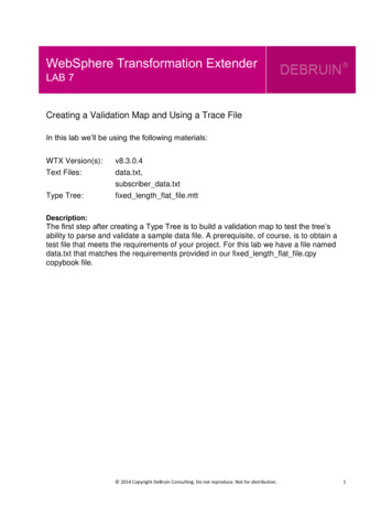
Enterprise Network SolutionsEE Connectivity Test CommandEE Tool Box The Enterprise Extender connectivity test command is useful in debuggingvarious network problems. This command can be used to test an existingEnterprise Extender connection, or it can be used to assist in diagnosing whyan EE connection cannot be established. The EE connectivity test will verify: EE line availability Address resolution capability EE partner reachability The output generated from thisrequest will show the reachabilityto the remote EE endpoint overall five UDP ports reserved for EE. When MULTIPATH function isenabled in the Enterprise Extendercapable TCP/IP stack, the EEconnectivity test is repeated foreach valid TCP/IP interface whichroutes EE traffic.D NET,EEDIAG,TEST YES,LIST DETAIL,ID ETU2HO.IST2067I EEDIAG DISPLAY ISSUED ON 07/11/07 AT 10:41:12IST1680I LOCAL IP ADDRESS 197.51.125.1IST1680I REMOTE IP ADDRESS 197.51.153.1.IST924I ----------IST2133I INTFNAME: LMTU2BR55INTFTYPE: MPCPTPIST2134ICONNECTIVITY SUCCESSFULPORT: 12000IST2137I1 197.51.155.14RTT:1IST2137I2 197.51.153.1RTT:4IST2134ICONNECTIVITY SUCCESSFULPORT: 12001IST2137I1 197.51.155.14RTT:2IST2137I2 197.51.153.1RTT:4IST2134ICONNECTIVITY SUCCESSFULPORT: 12002IST2137I1 197.51.155.14RTT:2IST2137I2 197.51.153.1RTT:5IST2134ICONNECTIVITY SUCCESSFULPORT: 12003IST2137I1 197.51.155.14RTT:2IST2137I2 197.51.153.1RTT:6IST2134ICONNECTIVITY SUCCESSFULPORT: 12004IST2137I1 197.51.155.14RTT:3IST2137I2 197.51.153.1RTT:5.28
Enterprise Network SolutionsEE Connectivity Test ExampleEE Tool BoxIPv4Cloud1IPv4 EE connection is establishedfrom HostA to HostB, but HPRperformance is OSA1OSA2Router9.67.1.5Router9.67.1.3When MULTIPATH is configured, theconnectivity test will verify allcomputed routes from HostA toHostBHostBz/OS9.67.1.6IPv4Cloud229
Enterprise Network SolutionsEE Connectivity Test Example .EE Tool BoxD NET,EEDIAG,TEST YES,IPADDR (9.67.1.1,9.67.1.6),LIST DETAILIST097I DISPLAY ACCEPTEDIST350I DISPLAY TYPE EEDIAGIST2119I ENTERPRISE EXTENDER DISPLAY CORRELATOR: EE00000EIST2067I EEDIAG DISPLAY ISSUED ON 10/04/05 AT 11:05:50IST1680I LOCAL IP ADDRESS 9.67.1.1IST1680I REMOTE IP ADDRESS 9.67.1.6IST2023I CONNECTED TO LINE LN11IST2126I CONNECTIVITY TEST IN PROGRESSIST314I END.!!30
Enterprise Network SolutionsEE Connectivity Test Example .EE Tool BoxIST350I DISPLAY TYPE EEDIAGIST2130I ENTERPRISE EXTENDER CONNECTIVITY TEST INFORMATIONIST2119I ENTERPRISE EXTENDER DISPLAY CORRELATOR: EE00000EIST2131I EEDIAG DISPLAY COMPLETED ON 10/04/05 AT 11:05:52IST2132I LDLC PROBE VERSIONS: VTAM V1 PARTNER V1IST1680I LOCAL IP ADDRESS 9.67.1.1IST1680I REMOTE IP ADDRESS 9.67.1.6IST924I ----------IST2133I INTFNAME: OSA1INTFTYPE: OSAFDDIIST2135ICONNECTIVITY UNSUCCESSFULSENSE: ***NA***PORT: 12000IST2137I1 9.67.1.2RTT:2IST2137I2 9.67.1.21D-1RTT:3IST2135ICONNECTIVITY UNSUCCESSFULSENSE: ***NA***PORT: 12001IST2137I1 9.67.1.2RTT:2IST2137I2 9.67.1.21D-1RTT:3IST2135ICONNECTIVITY UNSUCCESSFULSENSE: ***NA***PORT: 12002IST2137I1 9.67.1.2RTT:2IST2137I2 9.67.1.21D-1RTT:4IST2135ICONNECTIVITY UNSUCCESSFULSENSE: ***NA***PORT: 12003IST2137I1 9.67.1.2RTT:2IST2137I2 9.67.1.21D-1RTT:4IST2135ICONNECTIVITY UNSUCCESSFULSENSE: ***NA***PORT: 12004IST2137I1 9.67.1.2RTT:2IST2137I2 9.67.1.21D-1RTT:3.!!!31
Enterprise Network SolutionsEE Connectivity Test Example .EE Tool BoxIST924I ----------IST2133I INTFNAME: OSA2INTFTYPE: OSAFDDIIST2134ICONNECTIVITY SUCCESSFULPORT: 12000IST2137I1 9.67.1.3RTT:9IST2137I2 9.67.1.11RTT:14IST2137I3 9.67.1.12RTT:19IST2137I4 9.67.1.5RTT:23IST2137I5 9.67.1.6RTT:27IST2134ICONNECTIVITY SUCCESSFULPORT: 12001IST2137I1 9.67.1.3RTT:8IST2137I2 9.67.1.11RTT:14IST2137I3 9.67.1.12RTT:17IST2137I4 9.67.1.5RTT:21IST2137I5 9.67.1.6RTT:25.IST2134ICONNECTIVITY SUCCESSFULPORT: 12004IST2137I1 9.67.1.3RTT:7IST2137I2 9.67.1.11RTT:11IST2137I3 9.67.1.12RTT:12IST2137I4 9.67.1.5RTT:17IST2137I5 9.67.1.6RTT:23IST924I ----------IST2039I CONNECTIVITY TEST INFORMATION DISPLAYED FOR 2 INTERFACESIST314I END!!32
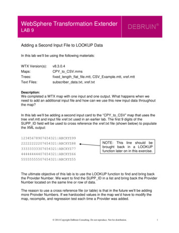
Enterprise Network SolutionsEE Connectivity Test Considerations EE connectivity test expects ICMP messages to be returned from intermediate hops Firewalls may be configured to block ICMP messages If possible, configure firewall to allow ICMP "Time Exceeded" messages IPv4: ICMP Message Type 11 IPv6: ICMPv6 Message Type 3 If allowing ICMP responses through the firewall is not possible, intermediate hops pastfirewall will appear as unresponsive, but final destination reachability can still bedetermined (see next chart) assuming destination has EE Test probe “responder”support. Firewalls may be configured to block UDP traffic Firewalls must allow UDP traffic on EE UDP ports 12000-12004 (both directions) Test probe response may route through firewall Probe response is not an ICMP message. It is a UDP datagram. EE Test probe "responder" support Support available for CS/Windows, CS/AIX, CS/Linux, PComm, andCisco SNASwEE Tool Box33
Enterprise Network SolutionsEE Connectivity Test w/Firewalls Blocking ICMPICMP Time Exceeded3Probe(TTL 2)Router2ICMPFirewallProbe(TTL 1)Router1FirewallRouterz/OSHost Az/OSHost BICMPICMP Time Exceeded45 *** Timeout/Retries ***6Probe(TTL 3)ICMP Time Exceeded78910*** Timeout/Retries ***Probe(TTL 4)Probe Reply (UDP)34
Enterprise Network SolutionsFirewall-Friendly EE Connectivity Test (V1R13) V1R13 introduced a new “firewall-friendly” form of the EE Connectivity Test The “DISPLAY EEDIAG,TEST YES,LIST SUMMARY” command will quickly verify partner reachability The TTL is set to the maximum hop limit so that the partner can quickly receive the Probe command and generate aUDP Probe reply packet. Intermediate hop analysis is not possibleD NET,EEDIAG,TEST YES,IPADDR (9.67.1.1,9.67.1.5),LIST SUMMARYIST097I DISPLAY ACCEPTEDIST350I DISPLAY TYPE EEDIAGIST2119I ENTERPRISE EXTENDER DISPLAY CORRELATOR: EE000001IST2067I EEDIAG DISPLAY ISSUED ON 08/29/05 AT 15:41:22.IST1680I LOCAL IP ADDRESS 9.67.1.1IST1680I REMOTE IP ADDRESS 9.67.1.5IST924I ----------IST2133I INTFNAME: LTRLE1AINTFTYPE: MPCPTPIST2134ICONNECTIVITY SUCCESSFULPORT: 12000IST2137I*NA 9.67.1.5RTT:6.IST2134ICONNECTIVITY SUCCESSFULPORT: 12004IST2137I*NA 9.67.1.5RTT:7IST924I ----------IST2139I CONNECTIVITY TEST RESULTS DISPLAYED FOR 1 OF 1 ROUTESIST314I END3
HATS HPR EBN DLSw Remote-API Application-gateways WebSphere Re-write everything to IP-based programming interfaces? CCL SNI IP Network TN3270 gateway SNA application gateway IP or SNA Network X.25 SNA Network Token-ring SNA Device such as ATM SNA Device (QLLC) APPN Network TN3270 clients S