Transcription
www.siepel.comGenerating high EM fields using modemode--stirredreverberation chambers for RTCA DO 160applicationsJean--François ROSNARHOJeanMicrowave & RF, March 23rd, 2016.
www.siepel.comTABLE OF CONTENTS2/ 57 NBR-800015 A1. RTCA DO 160 requirements2. Reverb chambers key points3. Comparison of test methods4. Design solutions for complete CS/RS tests5. Siepel EOLE series6. Conclusion
Microwave & RF 2016www.siepel.com1.3/ 57 NBR-800015 ARTCA DO 160 requirements
RTCA DO 160 - RequirementsRTCA DO160 G (2010)EMC tests on airborne equipmentwww.siepel.comSection 20 : EMS testsConducted10 kHz – 400 MHzRadiated100 MHz – 18 GHz
RTCA DO 160 - RequirementsRTCA DO160 G (2010)www.siepel.comConducted SusceptibilityRequires a shielded enclosure and test planeCurrent injected on bundle cables by InjectionProbes (10 kHz – 400 MHz)
RTCA DO 160 - Requirementswww.siepel.comConducted Susceptibility Test SetupTest bench withconductive surface(S 2.5 m²)bonded to theshielded enclosureA shielded room oran anechoicchamber
RTCA DO 160 - RequirementsRadiated Susceptibility : 100 MHz – 18 (40) GHzwww.siepel.comSection 20.5Tests in an anechoicchamber (AC)And / OrSection 20.6Tests in a mode-stirredreverberation chamber (MSRC)
RTCA DO 160 - RequirementsRadiated Susceptibility : 100 MHz – 18 (40) GHzwww.siepel.comCW testsup to 490 V/mPulse Modulated TestsUp to 7,200 V/m
Microwave & RF 2016www.siepel.com2.9/ 57 NBR-800015 AReverb Chambers Key Points
How does it work ?A mechanical mode stirrer modifies field configuration in a cavitywww.siepel.comSignal Gen.
How does it work ?www.siepel.comSignal Gen.Field configuration
Statistical uniformityMaximum field level (X, Y, Z, Total) on one rotation (fixed frequency)V/m1 turn of stirrerMaximum field level (X, Y, Z, Total) on 9 probe locationswww.siepel.comV/m9 probe locationsThe field is statistically homogeneous and isotropic within theworking volume averaged over one complete rotation, from LUF
How does it work ?www.siepel.comCalibration of the Reverb Chb provides 2 main characteristicsSatistical uniformityDeviation on the maximum field of eachfield component (EX, EY, EZ) and total field(ET), on each of the 9 probe locations mustbe below the allowed standard deviationlimit of DO 160Determines Lowest frequency of UseOf the MSRCNormalized E FieldField which is obtained for 1 W powerdelivered on the input connectorof the Tx antennaDetermines the power level to beprovided to reach the target E-fields
How does it work ?Design key point of the Reverberation Chamberwww.siepel.comSmaller Reverb ChbLUF will be higherNormalized E-Field will be higherLarger Reverb. ChbLUF lower (100 MHz)Normalized E-field will be lowerTrade-off to determine the suitable solution to perform RS tests
Microwave & RF 2016www.siepel.com3.15/ 57 NBR-800015 AComparison of test methods
www.siepel.comAnechoic Ch. Vs MSRCFree Space environmentTest distance 1 mPropagated waves, absorbed bythe wallsDeterministic description of thefieldsAnisotropic testsReverberating environmentNo specific test distanceReflections on the wallsRandom description of the fieldsIsotropic tests
Anechoic Ch. Vs MSRCwww.siepel.comDO 160 G section 20 : both can be used for Radiated and ConductedSusceptibilityDO 160 G section 21 : both can be used for Radiated and ConductedEmissionsWhat are the criterion of choice ?
Anechoic Ch. Vs MSRCAnechoic chamber (AC)Conducted tests possible on a test bench (shielded room)www.siepel.comRadiated tests possible with RF absorbers on the wallsCompliance of the chamber :Reflectivity level of the absorbers -6 dB (100 MHz f 250 MHz)Reflectivity level of the absorbers -10 dB (f 250 MHz)660 mm high absorbers typicallyRadiated tests done on a planeThe EUT must be rotatedField strength related to test distance (1m)One single AC can be used for all CS & RS tests
Anechoic Ch. Vs MSRCReverb chamber (MSRC)Conducted tests possible on a test bench (shielded room)Radiated tests without absorbers on the wallswww.siepel.comCompliance of the chamber :Lowest Frequency of Use (LUF)Normalized Field high enough to provide target fieldRadiated tests done on a volumeThe EUT needs not being rotatedField strength related to Normalized Field (dependent on MSRC size)Multiple MSRC can be used for all CS & RS tests (optimization)
Anechoic Ch. Vs MSRCwww.siepel.comPower levels needed to reach target fieldTechnical difficulties & Budget increase
Microwave & RF 2016www.siepel.com4.21/ 57 NBR-800015 ASolutions for complete CS/RS tests
Technical solutions3 main frequency rangeswww.siepel.com100 – 400 MHzCW tests onlyLevels 200 V/m0.4 – 1 GHzCW & PM TestsUp to 1,400 V/mLPDA Antenna1 – 18 GHzCW & PM TestsUp to 7,200 V/mHorn Antenna
Technical solutions3 main frequency ranges100 to 400 MHzCW field levels allow to use an Anechoic Chamber or a Reverb Chamber withavailable instrumentationwww.siepel.com400 to 1,000 MHzCW field levels allow to use an Anechoic Chamber or a Reverb Chamber withavailable instrumentationCat L PM field levels make the use of an Anechoic Chamber costly1 to 18 GHzCW field levels allow to use an Anechoic Chamber or a Reverb Chamber withavailable instrumentationCat L PM field levels make the use of an Anechoic Chamber unrealistic
Technical solutionsIt is possible to use several combinations for RS testing :www.siepel.com1 Anechoic Chb (100 MHz to 400 MHz) 1 Reverb. Chb (400 MHz – 18 GHz)Realistic for an existing laboratory with ACPossible with affordable instrumentation if cat. G & L not required1 Anechoic Chb (100 MHz to 400 MHz) 2 Reverb Chb ([400 MHz ; 1 GHz] & [1 ; 18 GHz])Realistic for a laboratory with existing ACAllows to consider cat. L testing at optimized budget
Technical solutionsIt is possible to use several combinations for RS testing :www.siepel.com1 Reverb.Chamber (100 MHz – 18 GHz)Possible but difficult for PM tests 1 GHz (cat. F/G/L)3 Reverb. Chambre ([100 ; 400 MHz] & [400 MHz ; 1 GHz] & [1 ; 18 GHz])Optimized solution for a new laboratoryOptimal power amplifier budget
Microwave & RF 2016www.siepel.com5.26/ 57 NBR-800015 ASiepel EOLE series
www.siepel.comUnique - high conductivity panelsComparison between 2 identical MSRC20% more field with aluminumInput power reduced by 2 dB
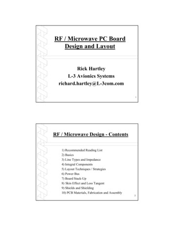
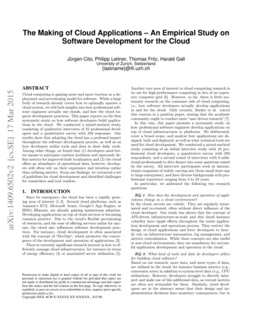
EOLE 100Frequency range of operation : 100 MHz to 18 (40) GHzwww.siepel.comSpecifications (typ.)Dimensions 7.5 x 5 x 4 mTest volume 3 x 2.3 x 1.7 mMinimum field strength @ 400 MHz & 1W : 30 V/m
www.siepel.comEOLE 100
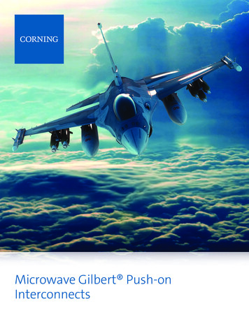
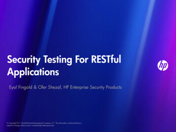
EOLE 400Frequency range of operation : 400 MHz to 18 (40) GHzwww.siepel.comSpecifications (typ.)Dimensions 3.45 x 2.52 x 2.94 mTest volume 2.66 x 1.25 x 1.36 mMinimum field strength @ 1 GHz & 1W : 85 V/m
www.siepel.comEOLE 400
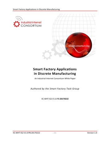
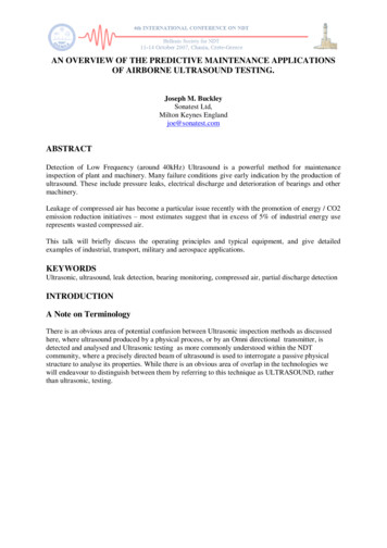
EOLE 1000Frequency range of operation : 1 GHz to 18 (40) GHzwww.siepel.comSpecifications (typ.)Dimensions 1.02 x 0.86 x 1.28 mTest volume 0.72 x 0.56 x 0.4 mMinimum field strength @ 1 GHz & 1W : 170 V/m
www.siepel.comEOLE 1000
Microwave & RF 2016www.siepel.com6.34/ 57 NBR-800015 AConclusion
DO160 - Advantages of MSRCHIGH FIELDS WITH LOW INPUT POWERwww.siepel.comTRADE OFF DIMENSIONS / LUF / POWERTOTAL GUIDANCE IN PROJECT DEFINITION
DO160 - Advantages of MSRCTURNKEY CAPABILITIESwww.siepel.comSINGLE RESPONSIBILITYFLEXIBLE AND UPGRADEABLE
Questions ?Contact for information pel.com
RTCA DO 160 requirements 2. Reverb chambers key points 3. Comparison of test methods www.siepel.com 4. Design solutions for complete CS/RS tests 5. SiepelEOLE series 6. Conclusion 2/ 57 NBR-800015 A. Microwave& RF 2016 1. RTCA DO 160 requirements www.siepel.com 3/ 57 NBR-800015 A. RTCA DO 160 -Requirements RTCA DO160 G (2010) EMC tests on airborne equipment