Transcription
XitaniumLED indoor driversSpot & downlight,LinearApril 2019April, 2019Design-in guide - Philips Xitanium Indoor LED drivers1
Published versions26 June 2015 First versionUpdated since previous versionXitanium indoor drivers of Spot & downlight, Linear DIG 2016 version2Design-in guide - Philips Xitanium Indoor LED driversApril, 2019
ContentsIntroduction to this guideApplicationsInformation and supportDetermine which documents contain what information4444Safety precautionsSafety warnings and installation instructions55Introduction to Xitanium Indoor LED driversIntroductionFeaturesForm factorsExplanation of the driver naming6671112Electrical design-inXitanium Driver Operating windowHow to Select an appropriate driverDriver wiring and connectionsConnectorsPoke-in ConnectorsHow to Use wires and cablesHow to Connect to a driver with JST connectoron outputAdjustable Output Current (AOC)– set the driver output currentDefault driver output currentHow to Determine AOC priority with TD driversHow to Set the output current via RsetHow to Set the output current via LEDsetHow to Program the output currentMains voltage fluctuations and behaviorInrush currentHow to Determine the number of drivers on a MCBSurge protectionTouch currentElectromagnetic compatibility (EMC)How to Improve EMI performanceElectrical isolation and protective earthHow to Use these Indoor LED driversas “independent” driver14141515161618April, 2019192020212123282829303131313233Thermal design-inIntroductionTc pointHow to Measure Tc at the Tc pointDriver lifetimeModule Temperature Protection (MTP)353535363636ControllabilityControl characteristicsTrailing edge (TE)1-10 V DimmingTD dimming: Touch and Dim & DALINon-dimmableApplication nPhilips MultiOne Interface toolPhilips MultiOne SoftwareSystem requirementsGetting StartedSettingsHow to See the programming taking effectAOC settingModule Temperature Protection (MTP) behavior settingConstant Lumen Output settingDCemDIM settingCorridor Mode settingHow to Set the DALI minimum dimming levelDriver diagnostics (TD drivers only)444444454545464647474849505152Quality and ReliabilitySwitching & cycling lifetime of LED driversElectrical failures due to switching Vmains on and offMechanical failures due to thermal cyclingStandards the drivers are tested against5353535355Disclaimer5634Design-in guide - Philips Xitanium Indoor LED drivers3
Introduction to this guideThank you for choosing Philips Xitanium drivers. In this guide youwill find the information needed to integrate these drivers into aLED luminaire or LED system.This edition describes the Xitanium LED drivers optimized forindoor lighting. We advise you to consult our websites for thelatest up-to-date information.ApplicationsThe Xitanium LED drivers are designed to operate LEDsolutions for indoor lighting, like offices, public buildings and retailenvironments. If you use Philips LED drivers in combination withPhilips LED modules, specific design-in guides are available fromthe below mentioned technology websites.Xitanium Indoor LED driversInformation and supportDownloads and informationPlease consult your local Philips office or ltiOneDatasheetCommercial leafletDesign-in guideDesign-in supportOn request Design-in support from Philips is available. For thisservice please contact your Philips sales representative.Determine which documents contain what informationIn order to provide information in the best possible way, Philips’philosophy on product documentation is the following. Commercial leaflet contains product family information &system combinations Datasheet contains the product specific specifications Design-in guide describes how the product is to be designed-inAll these documents can be found on the download page of theOEM website www.philips.com/technology. If you require anyfurther information or support please consultyour local Philips office.4Design-in guide - Philips Xitanium Indoor LED driversApril, 2019
Safety precautionsWarnings: Avoid touching live parts! Do not use drivers with damaged housing and/orconnectors! Do not use drivers with damaged wiring! Class I luminaires must be connected to protective earth! Switchable function to make the open load on the driveroutput is abnormal condition, it is not an intended applicationthat be allowed.Safety warnings and installation instructionsTo be taken into account during design-in and manufacturing Do not use damaged or defective contacts or housings Do not use damaged products Do not service the driver when the mains voltage is connected;this includes connecting or disconnecting the LED load Cap off all unused wires to prevent accidental contact with theluminaire, driver housing or accidental touching Do provide an adequate earth connection when applicable The luminaire manufacturer is responsible for its own luminairedesign and has to comply with all relevant safety standards The Xitanium Indoor LED drivers are intended for indooruse and should not be exposed to the elements such as snow,water and ice. It is the luminaire manufacturer’s responsibility toprevent exposure For the strain relief installation, Crosshead PH-2 Screw isrecommended to be used, recommended torque requirementfor screw is 0.7 0.9 N.m. In case driver being used for the independent application, makesure to keep the driver dry, acidfree, oilfree, fatfree and at least20mm distance from the body which is not the mountingsurface to wall for the sufficient thermal dissipation and do notexceed the maximum ambient temperature (ta) stated on thedevice For track drivers, due to different track types’ size andtolerance, to ensure the connection between driver and track,please move the position on the track if the conductive is notgood, track drivers are recommended to hang vertically, and itcan withstand 50N force. After turning on the driver, pleasethumb the on/off wheel to 'on' position.Philips Design-in support is available; please contact yourPhilips sales representative.April, 2019Design-in guide - Philips Xitanium Indoor LED drivers5
Introduction to Xitanium IndoorLED DriversXitanium Indoor LED driversIntroductionXitanium LED drivers are designed to operate LED solutions forgeneral lighting applications such as lighting in office, downlighting,spot/accent lighting and industry applications. Reliability isunderpinned with 5 year warranty, enhanced by specific featuresthat protect the connected LED module, e.g. reduced ripplecurrent ( 4%) and thermal de-rating. Most drivers feature centralDC operation.In the coming years LEDs will continue to increase in efficiency,creating generation and complexity challenges for OEMs. WithXitanium LED drivers, flexibility in luminaire design is assuredthanks to an adjustable (selectable) output current. Applicationoriented operating windows offer the flexibility required toprovide the stable lumen output and light quality levels thatlighting specifiers and architects demand. And the adjustableoutput current also enables operation of various LED PCBsolutions from different manufacturers.The remarkable energy savings and CO2 reductions achievedwith LED lighting can be further extended with dimming.Xitanium Indoor LED drivers offer a range of dimming options.The 1-10V and TE interface allows for simplified, one-waymanagement, while the DALI interface makes any installation withthe Xitanium driver ready for a fully networked control system.Alternatively these Dali drivers also are suitable to interface withTouch and Dim dimming.Xitanium LED driver versionsThe Xitanium LED drivers described in this guide are availablein different versions, e.g. both isolated and non-isolated versions,non-dimmable and dimmable (1-10 V, trailing edge dimming (TE),Touch and Dim & DALI (TD)) and come in a wide range ofpower ratings that enable the most popular light output levels forgeneral lighting applications. We recommend you always checkour Xitanium LED driver commercial leaflet for the most upto-date overview of our range. This leaflet can be found on thedownload section of www.philips.com/technology.6Design-in guide - Philips Xitanium Indoor LED driversApril, 2019
FeaturesAdjustable Output Current (AOC)Flexibility in luminaire design is ensured by the adjustable outputcurrent (AOC). The adjustable output current enables operationof various LED configurations from different LED manufacturerswhilst also ensuring the solution remains “future proof ” for newLED generations. The output current can be set with an externalresistor (Rset) in case this provision is there in the selected driver.With the TD drivers, the output current setting can also beprogrammed using the Philips MultiOne programminghardware interface and the matching software “MultiOnedriver configurator”. Drivers with SimpleSet functionality canbe configured with the Philips MultiOne Software and theSimpleSet interface.More information about AOC and how to set the output currentcan be found in the chapter “Electrical design-in”. Informationabout configuring drivers with SimpleSet can be found in thechapter “Configurability”.ControllabilityThe Xitanium Indoor LED drivers are available in 3 differentversions: Non-dimmable 1-10 V dimming (available for linear drivers) Trailing edge dimming (TE, available for Spot & downlightdrivers) Touch and Dim & DALI (TD)Amplitude Modulation (AM) output dimmingPhilips Xitanium indoor LED drivers dim the output to the LEDsby means of Amplitude Modulation dimming (AM). This means atno stage of the dimming range Pulse Width Modulation dimming(PWM) at the output to the LEDs is involved. AM dimmingguarantees the most smooth and flickerfree operation over theentire dimming range.The way of controlling is shown in the name of the driver. If nodimming protocol is given in the name, the Xitanium driver canonly be used as a nondimmable driver. The output current can beset as described in the Electrical design chapter. More informationabout the dimming protocols can be found in the Controllabilitychapter.April, 2019Design-in guide - Philips Xitanium Indoor LED drivers7
Active cooling ( available for Spot & downlight drivers)Selected Xitanium LED drivers feature a 12V output to operateactive cooling. Please check the datasheet atwww.philips.com/technology to know if the selected driver hasthis feature.Thermal de-ratingThermal de-rating of your LED is possible by integrating an NTC(Negative Thermal Coefficient) component on the LED PCB(Printed Circuit Board) and connecting this NTC to the driver’sNTC input.More details about NTC resistor can be found underchapter “Thermal Management”.Hot wiringSome of Xitanium Indoor drivers within the statementand performance segments can be serviced, connected ordisconnected from the LED load when the mains voltage isconnected. Please make sure that all electrical safety regulationsare followed when working on a Xitanium driver while powered.Module Temperature Protection (MTP) – adjustable on TDdrivers onlyThis feature helps to protect the LEDs when operated in a hotambient environment. The driver helps to regulate LED moduletemperature by regulating the output current. An NTC (NegativeTemperature Coefficient resistor) must be present on the LEDmodule and connected to associated pins on the driver in orderto be able to make use this feature. Programmable drivers allowthe dimming behavior to be changed.More information on this feature can be found under chapter“Thermal Management”.8Design-in guide - Philips Xitanium Indoor LED driversApril, 2019
Constant Light Output (CLO) – TD drivers onlyTraditional light sources suffer from depreciation in light outputover time. This applies to LED light sources as well. The CLOfeature enables LED solutions to deliver constant lumen outputthrough the life of the light engine. Based on the type of LEDsused, heat management and driver current, it is possible toestimate the depreciation of light output for specific LEDs andthis information can be entered into the driver. The driver countsthe number of light source working hours and will increaseoutput current based on this input to enable CLO.Since the CLO curve is not generic, the OEM needs todetermine the appropriate CLO curve. This can be used todifferentiate on e.g. lumen output or power consumption overlifetime. The CLO feature can be programmed with the PhilipsMultiOne configurator software.More information can be found under chapter “Controllability”.More information can be found on www.philips.com/multione.DC mains operationIt is possible to connect the mains input of the Xitanium driverdirectly to a DC power net (e.g. central emergency system). Thisleads the driver to continue normal output when switched toDC mains. On selected TD drivers DCemDIM is available,allowing a pre-defined dim level (%) of the driver’s output whenswitched to DC. More on DCemDIM in section Controllability.Check for requirements and default values the driver’s datasheetin the download section on www.philips.com/technology.T1April, 2019T2Presence detected,No presence,Light fadesftolight onlight stays onbackgk round levelat normal levelat normal levelT3Light switches offDesign-in guide - Philips Xitanium Indoor LED drivers9
Corridor Mode – TD drivers onlyCorridor Mode is typically used in corridors, stairwells, entrancehalls, storage rooms, underground car parks, pedestrianunderpasses, underground railway stations and lifts. It is a simplefunction, available with Xitanium indoor TD LED drivers, thatcontrols the light level when presence is detected by a simpleon/off mains sensor. It is easy to use and can be activated usingdefault parameters, so no programming via software is required.When the sensor detects presence, the light switches on. Whenit no longer detects any presence, instead of the light switchingoff immediately, the TD driver takes over control of the light leveland dims it down to a background level. The settings can becustomized using the Philips MultiOne configurator software.PETouch and DimTTouch and DimTConnecting a sensor to the Dali input to utilize Corridor ModeHow does it work?A simple on/off mains sensor (e.g. PIR or micro wave) providesthe signal and is connected to the Touch and DIM/DALIconnection of the TD driver. When the input detects mainspower on the DALI connection, it switches on the light to thenormal level. When the mains signal of the sensor is switched onfor more than 1 minute (default activation time), the TD drivergoes into Corridor Mode.When the on/off sensor no longer detects any movement, it goesinto its delay time. After the delay time of the on/off sensor haselapsed, the TD driver no longer receives a mains signal on theDALI input and takes over control of the light level by going intoits Corridor Mode sequence:1. During the delay time the driver maintains the light at thenormal level2. During the fade time the driver dims the light to thebackground level3. During the prolong time the driver maintains the light at thebackground level, after which the light is switched off.If the on/off sensor detects movement at any point during theCorridor Mode sequence, the light will revert to the normal level.Newly released Xitanium indoor TD drivers incorporate theCorridor Mode feature. The datasheet states if for the driver youuse this feature is present. For the default settings please checkthe associated datasheet of the driver you use, to be found in thedownload section on www.philips.com/technology.10Design-in guide - Philips Xitanium Indoor LED driversApril, 2019
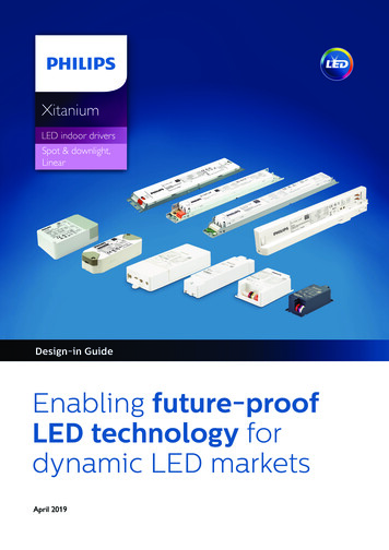
The settings can be customized to suit your application usingthe Philips MultiOne configurator software (see sub section“Programming” under 2920755121.150 1200 285151.285Lamp VoV ltage (V)Linear driver Form FactorLH Form Factor: 3 mounting optionsFrom left to right: Independent, Screw, Click mountingDriver diagnostics (actual measurements and logging)– TD drivers onlyOn selected TD drivers the diagnostics functionality is available.The purpose of Diagnostics is to gather information and helpdiagnose the history of the driver and connected LED module.The diagnostics consist mainly of counters which keep track ofspecific variables like for example the number of startups ofthe driver, temperature of driver and LED modules, current andvoltages etc.When the driver is shutdown the diagnostics data is storedautomatically.Form factorsLinear housingThe housing of the Xitanium Indoor Linear LED drivers has aform factor compatible with typical fluorescent driver housingdesign.The linear housing design (LH)The linear housing design incorporates three different mountingoptions: Independent Screw Click mounting.Screw-mounting and Click-on parts are assembled within theindependent housingThe square independent housing design (SH)The square independent housing is equipped with a 12 Vpower output for active cooling, strain relief possibility for allcables and loop through functionality for the mains wiring.SH Form FactorSmall housing design (/s)The “/s” is the most compact Xitanium form factor within theperformance segment. It has a form factor identical to the PhilipsHID-PrimaVision driver, enabling an easy transformation of yourluminaire from HID to LED./s Form FactorApril, 2019Design-in guide - Philips Xitanium Indoor LED drivers11
Strain relief blocksfor the /m driver/m Form Factorbottom plate for the /m driver,only available for ChinaMini housing design (/m)The “/m” drivers are placed within the Core segment of theXitanium drivers. It has a form factor which is exactly the sameas the Philips HID-PrimaVision mini, thus helping you to easilytransform your luminaire from HID to LED. These drivers canbe adapted for using in independent applications by the use ofa strain relief cap and bottom plate (only be available in China)those can be ordered separately, as an accessory. This will ensurethat the driver is thermally protected and safe to use in ceilings.Note: There is a power limit for the use of this accessory. Onlydrivers up to 36W can be used in combination with the capfor independent use. 50W drivers are NOT permitted forindependent use.The potted independent housing designThese potted drivers have Form Factor for single output andstand-alone installations.Potted Independent Form FactorExplanation of the driver namingThe names of the drivers are defined as shown in the examplebelow.Example of linear driveXitanium : Brand name for highly efficient and extremelyreliable LED drivers75 W: Maximum output power0.12-0.4 A : Output current range215 V: Maximum DC output voltageTD: Dimming protocol (Touch and Dim & DALI)230 V: Mains AC input voltage12Design-in guide - Philips Xitanium Indoor LED driversApril, 2019
Example of point driverXitanium : Brand name for highly efficient and extremelyreliable LED drivers17W: Maximum output powerLH: Linear Housing0.3-1A: Output current range24V: Maximum output voltage (minimum being 50% ofthis value)TD: Dimming protocol (Touch & Dali)/I: Independent housing designs: Small version230V: Mains AC input voltageNaming of the driversI: Independent housing designTE: Trailing edge dimmingTD: Touch & DALI dimming/s: Small housingSH: Square independent housingLH: Linear independent housing/m: Mini housing (HID-PrimaVision mini form factor)April, 2019Design-in guide - Philips Xitanium Indoor LED drivers13
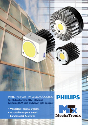
Electrical design-inXitanium Driver Operating windowLED technology is rapidly evolving. Using more efficient LEDs ina next generation means the same light output can be achievedwith less power, hence lower drive currents. At the same time,LEDs can be driven at different currents levels based on theapplication requirement. Typically, LED drivers are available indiscrete current levels e.g. 350 mA, 500 mA or 700 mA. It isoften necessary to replace a driver when more efficient LEDs ordifferent LED boards become available.Output voltage [V]2505200131504100250000.10.20.30.40.5Output current [A]1.2.3.4.5.Required set point for the LED solutionCurrent can be set to needs within rangeDriver adapts to required voltage, given it fits rangeDriver minimum power limitDriver maximum power limitExample of a Driver Operating WindowNote: by means of dimming it is possible to go below theminimum value of the specified output current.14One of the key features of the Xitanium LED drivers is theadjustable output current (AOC), offering flexibility, differentiationfor the OEM and futureproof luminaire design. The Xitaniumdrivers can operate in a so called “operating window”. Thispower window is defined by the maximum and minimum voltage(V), current (A) and power (W) that the driver can handle. Anexample of an operating window is shown on the left. The areaindicates the possible current /voltage combinations. The currentyou select will depend on the type and manufacturer of theLEDs, the specific LED configuration of the PCB design and thedesired output (lm) per LED. The voltage is the sum of the LEDsused (total Vf string). Both the operating window and defaultcurrent setting of every driver can be found in the datasheets inthe download section on www.philips.com/technology.The output current of these drivers can be set in two ways.1. By connecting a specific resistor value to the driver’s Rsetinput.2. Drivers with SimpleSet functionality can be configured usingthe Philips MultiOne software and SimpleSet interface.3. TD driver versions can be programmed via the MultiOneinterface in order to set the desired current, more informationcan be obtained at www.philips.com/multiOne.Design-in guide - Philips Xitanium Indoor LED driversApril, 2019
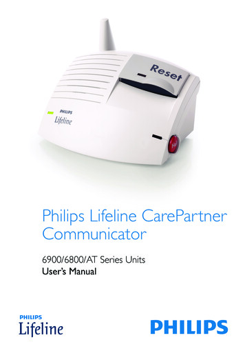
* Note: when connecting Philips LED Lines to the driver, the typeof LED board (LV or HV) determines this requirement. HybridLED boards can be used on both type of drivers, indicated incommercial leaflet LED Lines, to be found in the downloadsection of www.philips.com/technologyHow to Select an appropriate driverDepending on you requirements several drivers can be foundas a solution for you. The following steps can help selecting thepreferred driver.** Note: for Philips LED Lines standard system configurations,driven at nominal current, are stated in the commercial leafletLED Lines, to be found in the download section ofwww.philips.com/technologyFor a full overview of available driver models, please refer to thecommercial leaflet Xitanium indoor LED drivers, to be found inthe download section of www.philips.com/technology, as are thedatasheets associated with the drivers you intend to use.Note: for a HV scenario that allows a 2 chain parallel solution, youare likely to find with steps described a lower rated driver power(e.g. 75 W for 1 chain versus 36 W for 2 chain solution)Driver wiring and connectionsExamples of driver lead wires with corresponding functions canbe seen in the figure on the left. Please check the driver’s pinningin the associated datasheet on www.philips.com/technology. Thefunction of each wire will be discussed further in detail in thefollowing chapters.NTC (thermal derating)RsetLED module settingNTCSignal groundXitaniumLED driver1. Determine your required drive current (Idrive) and voltage (Vf)2. Calculate required power via Pdrive Vf x Idrive (W)3. Determine which type* of driver do you need; Isolated orNon-isolated Collect the associated datasheets from thewebsite.4. Does required current fit current range of driver?- Idriver minimum Idrive Idriver maximum?5. Does required voltage fit voltage range of driver?- Vdriver minimum Vf Vdriver maximum?6. Does required power fit power range of driver?- Pdriver minimum Pdrive Pdriver maximum?7. Choose your type** of dimming (TD/Dali, 1-10 V ornon-dimmable)LED engineSingle channel driverCurrently all the Xitanium Indoor LED drivers are single channeldrivers. This means for drivers with a double “ ” and “-“ outputthat these outputs are in parallel inside the driver. So you canonly set one current.Schematically representation of the driver’s output interfacesApril, 2019Design-in guide - Philips Xitanium Indoor LED drivers15
1234567BlackYellowRedBlueOrangeGree- Current- Power ground- NTC- Rset1- Rset2- Signal groundJST connector (driver side) pin layoutJST connector with soldered rseConnectorsDifferent connectors are used on the Philips Xitanium Indoordrivers. More info about the type of connector and wiring(diameter, length, etc.) can be found in the datasheet. Thedatasheets of each driver can be downloaded viawww.philips.com/technology.JST ConnectorsSome of the Xitanium LED drivers feature a JST connector thatcombines the power connection to the LEDs with the Rset orNTC features. The pin layout for this connector is shown on theleft. In case a JST connector is to be used to set the current viaan Rset, there are 3 options:1. Use a JST connector with a resistor soldered on to pins 6 and7 for Rset2 and pins 5 and 7 for Rset1.2. Use a JST-poke-in adaptor3. Integrate the resistor into the cable running from the driverto the module (valid for modules that have cables connectingthe JST connector of the driver to the module). In this case,the resistor must be integrated into the wire connecting theappropriate pin for Rset 1, Rset 2 or LEDset.Poke-in ConnectorsSome Xitanium LED drivers feature poke-in connectors on theinput and output side of the driver for ease and flexibility.Example of the JST to Push-in adapterNote: All new drivers and modules are moving away from suchconnectors towards poke-in options. Please refer to the driver(and module) datasheet at www.philips.com/technology fordetails on the type of connector available. In case a choice ismade to use a driver with a JST connector and a module withpoke-in connectors, there are special cables available to allow forthis. More information can be seen in the datasheets of themodules or you can contact your Philips representative.Poke-in Connectors16Design-in guide - Philips Xitanium Indoor LED driversApril, 2019
Mains ConnectorsOrange push-in connectors are used to connect the drivers tothe mains. The connector for PE is colored green (if present). TheXitanium drivers with the SH form factor have 2 connectors foreach mains connection to enable loop through functionality.DALI – Touch Dim ConnectorsBlue push-in connectors are used to connect the DALI or TouchDim connection wires to the Xitanium driver.Connection details in the case of poke-in connectorsThe connections for the mains, 12 V output and the Rset aredone using a poke-in connector for selected drivers. Please keepin mind the following while making the connection: Make sure to push in the springs before inserting the wires inorder to ensure a good connection. While connecting the resistor, please refer to the pictureshown. The resistor must be inserted such that there is nopossibility of a short.1234567BlackYellowRedBlueOrangeGreen- Current- Power ground- NTC- Rset1- Rset2- Signal groundSpecial attention for 75 W and 110 W Xitanium LED driversDue to the higher output voltage ( 100 V) of these LED driversmore creepage/clearance distance is required for safety reasons.The terminal of the LED driver output current has thereforebeen moved from pin 2 to pin 1.JST connector (driver side) pin layout 75 W & 110 WApril, 2019Design-in guide - Philips Xitanium Indoor LED drivers17
How to Use wires and cablesIn the datasheet of the driver you use it is stated what Wire diameters are accepted Strip length of the wires are accepted Up to what wire length the drivers are tested on EMCExamples of what solutions could look like for pairing wiresDirect wiring between driver and LED boardsBe informed that no components are allowed between theLED driver and LED boards other than connectors and wiringintended to connect the LED driver to the LED board. Forexample it is not allowed to install a switch between the driverand LED boards.2 wires into one connector holeIn some scenarios two wires need to be connected to oneconnector hole. In this case the pairing has to be done outsidethe driver, resulting in only one wire going into the driver. Twowires into one connector hole are not supported.FerrulesThe reliability of twin-wire ferrules (or wire end stop), acceptingthe wires intended to use, should be checked with the supplier ofthese ferrules.18Design-in guide - Philips Xitanium Indoor LED driversApril, 2019
How to Connect to a driver with JST connector onoutputSome Xitanium Indoor LED Drivers carry a JST outputconnector (non-isolated models only). Until these drivers getupdated with a push-in connector be advised to use the JST-topush-in adapter.1. Connecting the LED board to the adapterOn the adapter IDC HV ( ) and PGND (-) are indicated (pin1 and 3).Connect IDC HV ( ) to LED board IN , PGND (-) to LEDboard IN-.2. Placing the Rset component into the adapter Rset2: place resistor into Rset2 connections (SGND and ISET2,pin 7 and 6). Alternatively, when using Rset1: place resistor into Rset1connections (SGND and ISET1, pin 7 and 5).Example of the JST to Push-in adapter3. Wire diameters accepted by the adapter AWG 24-16 0.2-1.5 mm2 solid and stranded 0.25-1 mm2 with ferrule Lead wires of the resistor componentOrdering information can be found in the Commercial Leafletof the Xitanium indoor LED drivers, located in the downloadsection on DC HV ( ) (LED )2BlackIDC LV ( ) (not used for linear)3YellowPower Ground (-) (LED -)4RedNTC5BlueIset1 (Rset1)6OrangeIset2 (Rset2)7GreenSignal Ground (for NTC & Rset)JST cable developed by OEMAny luminaire design needs its own approval, organized by theresponsible OEM, irrespective of the length of cable used. If youprefer to develop a JST-cable the specification should meet IEC/EN requirements. When selecting wiring, it must be borne inmind that the cable must not emit hazardous gases or catch firewhen expo
Philips MultiOne Interface tool 44 Philips MultiOne Software 45 System requirements 45 Getting Started 45 Settings 46 How to See the programming taking effect 46 . with LED lighting can be further extended with dimming. Xitanium Indoor LED drivers offer a range of dimming options.