Transcription
Technical Note – SunSpec Logging in SolarEdge InvertersVersion 2.4, December 20211Version HistoryVersion 2.4 (December 2021): Updated Use Cases for MODBUS over TCP – Multiple Inverter ConnectionVersion 2.3 (February 2021): Updated Modbus Register MappingsVersion 2.2 (December 2020): Updated Modbus Register MappingsVersion 2.1 (September 2020): New multiple MPPT inverter extension model for Synergy invertersVersion 2.0 (January 2019): Addition of SetApp information Addition of Modbus over TCP option Addition of reference to inverter upgrade procedure Addition of Appendix C – Encoding and Decoding 32-bit Values in Modbus.Version 1.0 (2016) – Initial ReleaseContentsTechnical Note – SunSpec Logging in SolarEdge Inverters . 1Overview . 2SunSpec Supported Inverters . 3Use Cases for MODBUS over RS485 . 3Use Cases for MODBUS over TCP. 7SolarEdge Device Configuration – Using SetApp . 10SolarEdge Device Configuration – Using the Inverter/Commercial Gateway Display (LCD) . 12Register Mapping – Monitoring Data . 15Multiple MPPT Inverter Extension Model . 18Meter Models . 20Appendix A – Supported MODBUS Request Methods . 31Appendix B – Response Time Information . 32Appendix C – Encoding and Decoding 32-bit Values in Modbus . 33Support Contact Information . 35Technical Note – SunSpec Logging in SolarEdge Inverters
2OverviewSolarEdge inverters support transmission of inverter-level monitoring data directly from the inverter to a local non-SolarEdge deviceusing the SunSpec open protocol for interoperability between devices in renewable energy systems. This option can be used alongsidethe connection to the SolarEdge monitoring server. This document describes the connection method and the protocol andconfigurations needed to implement this feature.Direct connection to a monitoring device is useful when a network connection is unavailable, when extensive custom data processing isrequired, or when authorities require direct access to monitoring data.In many cases, it is possible – and recommended – to employ the direct connection alongside a SolarEdge monitoring platformconnection. Connection to the monitoring platform enables all the monitoring benefits, primarily:Proactive installer maintenance and real time troubleshooting by SolarEdge support, using with the physical mapping availableonly in the monitoring platformModule-level monitoringCommunication TechnologiesSolarEdge uses an open, industry-standard communications stack in order to provide efficient messaging between SolarEdge and thirdparty devices and applications.The communications stack components are briefly described below.SunSpecSunSpec is an application-layer communications protocol designed to achieve interoperability between Distributed Energy Resource(DER) components and smart grid applications.ModbusModbus is a serial communications protocol typically used to connect data collection terminals to a centralized processing unit.SolarEdge products use Modbus to perform SunSpec messaging over two types of physical/link-layer channels:Modbus RTU: Remote Terminal Unit (RTU) Modbus over a serial RS485 connectionModbus TCP: Modbus over an Ethernet connectionSolarEdge systems support a single Modbus Leader only – either single Modbus RTU or single Modbus TCP.Technical Note – SunSpec Logging in SolarEdge Inverters
3SunSpec Supported InvertersDepending on their type, SolarEdge devices may be configured in either of the two ways:Using SetAppUsing the LCDAll SolarEdge inverters with SetApp configuration are SunSpec-supported.SolarEdge inverters with the LCD that have Firmware version 3.xxxx and above only are SunSpec-supported.1.To check the inverter firmware versions (for inverters with the LCD):Short press the LCD light button until reaching the following screen:I D :# # # # # # # ## #D S P 1 / 2 : x . x x x x / x . x x x xC P U: 0 0 0 2 . 0 4 9 6C o u n t r y : X X X X X2.If required, upgrade to the latest available firmware, as described grading an inverter using micro sd card.pdf.Use Cases for MODBUS over RS485This section describes RS485 options to connect the inverter to a non-SolarEdge monitoring device.Physical ConnectionThe connection is performed using an RS485 connector with a twisted pair cable. The transmission mode in SolarEdge inverters is set toRTU (binary).The COM port default properties are: 115200 bps, 8 data bits, no parity, 1 stop bit, no flow control. Baud rate can be changed between9600bps to 115200bps (supported from CPU version 2.0549).The RS485 bus can be configured to support connection either to a non-SolarEdge monitoring device or Leader-Follower connectionbetween SolarEdge inverters. Therefore, a Follower inverter cannot communicate simultaneously with a Leader inverter and with a nonSolarEdge monitoring device on the same RS485 bus.All SolarEdge inverters with SetApp configuration have two built-in RS485 ports. An inverter can act as Leader on both portssimultaneously.A Commercial Gateway with LCD can act as Leader on one of the built-in RS485 ports and on the RS485 Plug-in.For more information on the RS485 Plug-in, RS485 expansion kit installation guide.pdfTechnical Note – SunSpec Logging in SolarEdge Inverters
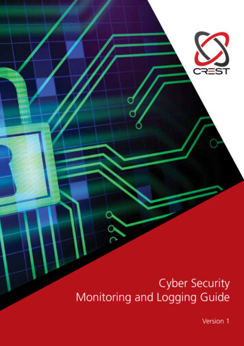
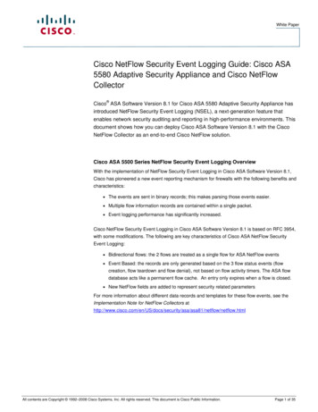
4Single Inverter ConnectionUse the RS485 bus for connecting to a non-SolarEdge monitoring device.Use the Ethernet connection or any of the optional wireless connection options to connect to the SolarEdge monitoring platform.Multiple Inverter ConnectionIf a second RS485 port is required to establish connection, use:RS485-2 for inverters with SetApp configurationRS485-E (requires a RS485 Plug-in) for inverters with an LCDConnection to a non-SolarEdge monitoring device only (without connection to the monitoring platform)Option 1 (direct connection) – Use RS485-1 to connect Followers to the Leader and the Leader to a non-SolarEdge monitoring device.Every inverter in the RS485 bus should be configured to a different device ID (MODBUS ID).Option 2 – Use RS485-1 to connect Follower inverters to the Leader; use either RS485-2 or RS485-E to connect the Leader to a nonSolarEdge monitoring device. Every inverter in the RS485 bus should be configured to a different device ID (MODBUS ID).Technical Note – SunSpec Logging in SolarEdge Inverters
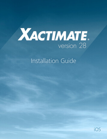
Connection to a non-SolarEdge monitoring device (with connection to the monitoring platform)5Use the RS485 bus for connection to a non-SolarEdge monitoring device. Every inverter in the RS485 bus should be configured to adifferent device ID (MODBUS ID).Option 1 (direct connection) – Connect each inverter to the router via Ethernet cables.Option 2 – Connect the router to one inverter only.Technical Note – SunSpec Logging in SolarEdge Inverters
6Connection to the monitoring platform and to a non-SolarEdge monitoring device using a CommercialGatewayUse the RS485-2 bus for connection to a non-SolarEdge monitoring device. Every inverter connected to the RS485 bus should beconfigured to a different device ID (MODBUS ID).If required, use the RS485-E bus for connecting a second chain of inverters.Technical Note – SunSpec Logging in SolarEdge Inverters
7Use Cases for MODBUS over TCPThis section describes MODBUS over TCP options to connect the inverter to a non-SolarEdge monitoring device.Single Inverter ConnectionUse Ethernet for connecting to a non-SolarEdge monitoring device.Multiple Inverter ConnectionConnection to a non-SolarEdge monitoring device only (without connection to the SolarEdge monitoringplatform)Use Ethernet for connection to a non-SolarEdge monitoring device.Technical Note – SunSpec Logging in SolarEdge Inverters
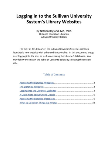
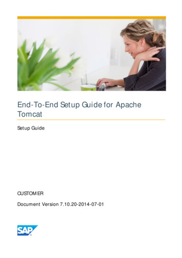
8Connection to a non-SolarEdge monitoring device (with connection to the SolarEdge monitoringplatform)Use Ethernet for connection to a non-SolarEdge monitoring device.Option 1 (direct connection) – Connect each inverter to the Ethernet router via Ethernet cables.Option 2 – Connect the Leader only to the Ethernet router via Ethernet cables.Connect a second chain of the inverters to the Leader inverter using RS485-2/RS485-E.Technical Note – SunSpec Logging in SolarEdge Inverters
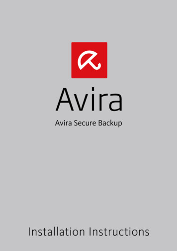
Connection to the SolarEdge monitoring platform and to a non-SolarEdge monitoring device using aCommercial Gateway9Use Ethernet for connection to a non-SolarEdge monitoring device. Every inverter connected to the RS485 bus should be configured toa different device ID (MODBUS ID).If required, use the RS485-E bus for connecting a second chain of inverters.Technical Note – SunSpec Logging in SolarEdge Inverters
10SolarEdge Device Configuration – Using SetAppThis section describes how to configure a SolarEdge device (inverter or Commercial Gateway) to be monitored by a non-SolarEdgemonitoring device using SetApp.NOTEThe actual SetApp screens may differ from the ones shown in this document.To reach the main setup menu, access SetApp and tap Commissioning Site Communication:Modbus over RS485 Configuration1.2.1.2.To configure the inverters (when used without the Commercial Gateway):Under the Site Communication menu, set the following: RS485-1 Protocol SunSpec (Non-SE Logger) RS485-1 Device ID, and enter the MODBUS address (a unique value 1 247). This will set the register C DeviceAddress.If needed, set the baud rate to a preferred value: RS485-1 Baud rate and enter the rate.To configure the inverters and gateway (when used with the Commercial Gateway):Inverter configuration: For all inverters, verify the following RS485 bus settings under the Site Communication menu: RS485-1 Protocol SolarEdge SolarEdge Follower RS485-1 Device ID [a unique value 1 247]Commercial Gateway configuration using the device display: Use RS485-1 to connect to the inverters. RS485-1 bus configuration isas follows: Communication RS485-1 Conf Device Type SolarEdge Communication RS485-1 Conf Protocol Leader Communication RS485-1 Conf Follower Detect3.The Commercial Gateway should report the correct number of Follower inverters. If it does not, verify the connections andterminations.Use RS485-2 to connect the Commercial Gateway to the non-SolarEdge monitoring device. Configure the RS485-2 bus settings asfollows, using the device display: Communication RS485-2 Conf Protocol SunSpec (Non-SE Logger)The Commercial Gateway device ID is irrelevant for communications, but needs to be set to a different ID than the one set forthe inverters. Communication RS485-2 Conf Device ID [use one of the higher IDs (e.g. 247) to make sure it is out of scope] The default baud rate is 115200 bps. If a different baud rate is required, select: Communication RS485-2 Conf Baud4.RateMake sure the device ID of the non-SolarEdge monitoring device is different from all other device IDs configured in the invertersand gateways.Technical Note – SunSpec Logging in SolarEdge Inverters
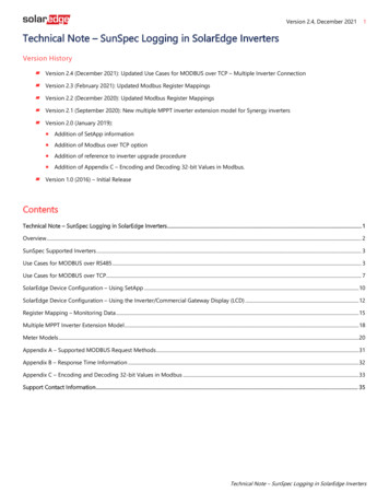
115.Connect the Commercial Gateway to router via the Ethernet interface and configure the following settings using the device display: Communication Server LAN Communication LAN Conf Set DHCP [Select Enable for DHCP or Disable for static IP configuration]For Static DHCP setting, configure as follows: Communication LAN Conf Set IP [Set inverters’ IP] Communication LAN Conf Set Mask [Set inverters’ subnet mask] Communication LAN Conf Set Gateway [Set inverters’ gateway]6. Communication LAN Conf Set DNS [Set inverters’ DNS]If the router is connected to the server, select Commissioning Status and verify that S OK is displayed under the main menu:StatusInverterSN 07318000CPower100kWVoltage277 VP OK: 138 of 141Optimizers ConnectedStatusProductionLimitVoltageTemp1.060.9 HzS OKServer Connected(LAN)SwitchCosPhi1.00FrequencyNo Limit20 CCommissioningONCountryNetherlandsFanOKMODBUS over TCP SupportMODBUS/TCP uses the Ethernet media in physical layers to carry the MODBUS message handling structure and can support a largenumber of devices in one network; it is easier to integrate into the Local Area Network (LAN) of a company, so it is the choice of moreand more customers.Here, it is used for remote 3rd party monitoring and control. MODBUS TCP is agnostic of the server connection. It works only over LAN.When configured, MODBUS TCP does not initiate a connection - the server waits for a client to connect. Only one connection issupported.NOTEThe MODBUS TCP function is disabled by default. When enabled, it supports TCP port 1502 by default. Portnumber can be reconfigured.Technical Note – SunSpec Logging in SolarEdge Inverters
12MODBUS over TCP Configuration1.2.3.To setup MODBUS TCP:Select Site Communication Modbus TCP Enable. A new Port menu is added to the screen (the default port is 1502)To modify the TCP port, select Port, set the port number and tap Done.NOTEThe default device ID of the inverter connected to the Ethernet is 1.NOTEThe TCP server idle time is 2 minutes. In order to leave the connection open, the request should be madewithin 2 minutes. The connection can remain open without any MODBUS requests.SolarEdge Device Configuration – Using the Inverter/Commercial Gateway Display(LCD)This section describes how to configure a SolarEdge device (inverter or Commercial Gateway) to be monitored by a non-SolarEdgemonitoring device using the LCD. To reach the main setup menu, follow the instructions in the Installation Guide of the specificSolarEdge device.Modbus over RS485 Configuration1.To configure the inverters (when used without the Commercial Gateway):Under the Communication menu, set the following: Communication Server Select any server connection, except for RS485 (if the inverter is not connected to theSolarEdge monitoring platform, select None. Communication RS485-1 Conf RS485-1 Conf Device Type Non-SE Logger RS485-1 Conf Protocol SunSpec RS485-1 Conf Device ID and enter the MODBUS address (a unique value 1 247). This will set the register2.1.C DeviceAddress.If needed, set the baud rate to a preferred value: RS485-1 Conf Baud rate and enter the rate.To configure the inverter (when used with the Commercial Gateway):Inverters configuration: For all inverters, set the following RS485 bus settings: Communication RS485-1 Conf Device Type SolarEdge Communication RS485-1 Conf Protocol Slave2. Communication RS485-1 Conf Device ID [a unique value 1 247]Commercial Gateway configuration: Use RS485-1 to connect to the inverters. RS485-1 bus configuration is as follows: Communication RS485-1 Conf Device Type SolarEdge Communication RS485-1 Conf Protocol Master Communication RS485-1 Conf Slave DetectThe Commercial Gateway should report the correct number of slaves. If it does not, verify the connections and terminations.Technical Note – SunSpec Logging in SolarEdge Inverters
133.Use RS485-2 to connect to the non-SolarEdge monitoring device. RS485-2 bus configuration is as follows: Communication RS485-2 Conf Device Type Non-SE Logger Communication RS485-2 Conf Protocol SunSpecThe Commercial Gateway Device ID is irrelevant for communications, but needs to be set to a different ID than the one set forthe inverters. Communication RS485-2 Conf Device ID [use one of the higher ID’s (e.g. 247) to make sure it is out of scope] The default baud rate is 115200 bps. If a different baud rate is required, select: Communication RS485-2 Conf Baud4.5.RateMake sure the device ID of the non-SolarEdge monitoring device is different from all other device IDs configured in the invertersand gateways.Connect the Commercial Gateway to router via the Ethernet interface and configure the following settings: Communication Server LAN Communication LAN Conf Set DHCP [Select Enable for DHCP or Disable for static IP configuration]For Static DHCP setting, configure as follows: Communication LAN Conf Set IP [Set inverters’ IP] Communication LAN Conf Set Mask [Set inverters’ subnet mask] Communication LAN Conf Set Gateway [Set inverters’ gateway]6.7. Communication LAN Conf Set DNS [Set inverters’ DNS]If the router is connected to the server, verify that the LCD panel displays S OK .Verify that the LCD panel of all inverters is S OK .MODBUS over TCP SupportMODBUS/TCP uses the Ethernet media in physical layers to carry the MODBUS message handling structure and can support a largenumber of devices in one network; it is easier to integrate into the Local Area Network (LAN) of a company, so it is the choice of moreand more customers.Here, it is used for remote 3rd party monitoring and control. MODBUS TCP is agnostic of the server connection. It works only over LAN.When configured, MODBUS TCP does not initiate a connection. The server waits for a client to connect. Only one connection issupported.NOTEThe MODBUS TCP function is disabled by default. When enabled, it supports TCP port 502 by default. The port numbercan be reconfigured.Technical Note – SunSpec Logging in SolarEdge Inverters
14MODBUS over TCP ConfigurationTo setup MODBUS TCP: Select Communication LAN Conf Modbus TCP (the default port is 502). To modify the TCP port, select Modbus TCP TCP Port, set the port number and long-press Enter.NOTEThe default device ID of the inverter connected to the Ethernet is 1.When the MODBUS TCP feature is enabled, the following status screen is shown:M o d b u sT C P : s t a t u s I P : 1 9 2 . 1 6 8 . 1 . 2 1 0P o r t : 5 0 2 e r r o rm e s s a g e Status: Init – Initializing server – This state only occurs after the first configuration until it reaches the ready status. This activitylasts about 10sec. Ready – The server is up and waiting for a client to connect. Connected – The client is connected. Failed – The server is unable to accept clients (see error message).Error messages: Disconnected – The Ethernet cable is not connected Gateway Ping Failed. – A ping to the 1st router failed No IP - Either no DHCP configuration or static IP configuration (no DHCP server that assigned an IP address) or need todefine a static IP.NOTEThe TCP server idle time is 2 minutes. In order to leave the connection open, the request should be madewithin 2 minutes. The connection can remain open without any MODBUS requests.Technical Note – SunSpec Logging in SolarEdge Inverters
15Register Mapping – Monitoring DataThis section describes the registers mapping for the inverter monitoring data (read-only MODBUS protocol data). The SolarEdgeinverter mapping for monitoring data is based on the open protocol managed by SunSpec: SunSpec Alliance InteroperabilitySpecification – Inverter Models v1.0. Refer to the SunSpec Alliance Interoperability Specification – Common Models (Elements)document for a detailed description of the protocol.The register mapping can be downloaded from the SunSpec Alliance web page: http://www.sunspec.org/.SolarEdge inverters support the following mappings:SunSpec module ID 101, 102 1 and 103 register mappings.SolarEdge three phase inverters with Synergy technology also support SunSpec module ID 160 register mappings.Common Model MODBUS Register MappingsThe base Register Common Block is set to 40001 (MODBUS PLC address [base 1]) or 40000 (MODBUS Protocol Address [base 0]).All parameters are defined as in the SunSpec Common block definition, except for the C Options register, which is set toNOT IMPLEMENTED.C Manufacturer is set to SolarEdge.C Model is set to the appropriate inverter model, e.g. SE5000.C Version contains the CPU software version with leading zeroes, e.g. 0002.0611.C SerialNumber contains the inverter serial number.C DeviceAddress is the device MODBUS ID.AddressSizeNameTypeDescription400012C SunSpec IDuint32Value "SunS" (0x53756e53). Uniquely identifies this as aSunSpec MODBUS Map40002400031C SunSpec DIDuint1640003400041C SunSpec Lengthuint16400204002116C ModelString(32)(base 0)(base 8161C ManufacturerC VersionC SerialNumberC alue 0x0001. Uniquely identifies this as a SunSpecCommon Model Block65 Length of block in 16-bit registersValue Registered with SunSpec "SolarEdge "SolarEdge Specific ValueSolarEdge Specific ValueSolarEdge Unique ValueMODBUS Unit IDSupported only in split-phase configurations (Japanese grid and 240V grid in North America)Technical Note – SunSpec Logging in SolarEdge Inverters
16Inverter Device Status ValuesThe following I Status * values are supported:ParameterValueDescriptionI STATUS SLEEPING2Sleeping (auto-shutdown) – Night modeI STATUS OFF1I STATUS STARTING3I STATUS MPPTGrid Monitoring/wake-up4I STATUS THROTTLEDInverter is ON and producing power5I STATUS SHUTTING DOWNProduction (curtailed)6I STATUS FAULTShutting down7I STATUS STANDBYOffFault8Maintenance/setupInverter Model MODBUS Register MappingsThe following table lists the supported MODBUS register values.Unsupported values are indicated by the NOT IMPLEMENTED value.The base register of the Device Specific block is set to 40070 (MODBUS PLC address [base 1]), or 40069 (MODBUS Protocol Address[base 0]).acc32 is a uint32 accumulator that should always increase. Its value is in the range of 0.4294967295.Scale Factors. As an alternative to floating point format, values are represented by Integer values with a signed scale factorapplied. The scale factor explicitly shifts the decimal point to left (negative value) or to the right (positive value).For example, a value “Value” may have an associated value “Value SF”Value “Value” * 10 Value SF for example: For “Value” 2071 and “Value SF” -2 Value 2071*10 -2 20.71 For “Value” 2071 and “Value SF” 2 Value 2071*10 2 207100Address(base 0)40069(base 1)40070SizeNameType1C SunSpec DIDuint16Units101 single phase102 split phase40070400711C SunSpec Lengthuint16Registers40072400731I AC 078400724007440075400764007740078400791111111I AC CurrentI AC CurrentBI AC CurrentCI AC Current SFI AC VoltageABI AC VoltageBCI AC VoltageCATechnical Note – SunSpec Logging in SolarEdge Voltsuint16Voltsuint16DescriptionVolts103 three phase50 Length of model blockAC Total Current valueAC Phase A Current valueAC Phase B Current valueAC Phase C Current valueAC Current scale factorAC Voltage Phase AB valueAC Voltage Phase BC valueAC Voltage Phase CA value
17Address(base 994010040101401034010640107401081SizeName400801I AC VoltageAN400821I AC VoltageCN 1(base 02401044010740108401091111111111112111111111111I AC VoltageBN 1I AC Voltage SFI AC PowerI AC Power SFI AC FrequencyI AC Frequency SFI AC VAI AC VA SFI AC VARI AC VAR SFI AC PFI AC PF SFI AC Energy WHI AC Energy WH SFI DC CurrentI DC Current SFI DC VoltageI DC Voltage SFI DC PowerI DC Power SFI Temp SinkI Temp SFI StatusI Status VendorTypeUnitsDescriptionuint16VoltsAC Voltage Phase A to N valueuint16VoltsAC Voltage Phase C to N valueuint16int16VoltsAC Voltage Phase B to N valueAC Voltage scale grees 16uint16uint16AC Power valueAC Power scale factorAC Frequency valueScale factorApparent PowerScale factorReactive PowerScale factorPower FactorScale factorAC Lifetime Energy productionScale factorDC Current valueScale factorDC Voltage valueScale factorDC Power valueScale factorHeat Sink TemperatureScale factorOperating StateVendor-defined operating state and errorcodes. For error description, meaning andtroubleshooting, refer to the SolarEdgeInstallation Guide.Supported only in split-phase configurations (Japanese grid and 240V grid in North America).Technical Note – SunSpec Logging in SolarEdge Inverters
18Multiple MPPT Inverter Extension ModelThe Multiple MPPT (Maximum Power Point Tracker) Inverter Extension Model (160) is supported for SolarEdge Synergy Inverters withfirmware version 4.13.xx or later.Address(base 0) (base 1)NameHeader (Size: 2 words)SizeTypeUnitsDescriptionValue 160Multiple MPPT Inverter Extension 12340124DCA SF1sunssfN/A4012540126DCW SF1sunssfFixed Block (Size: 8 040131DCV SFDCWH SFEvtNTmsPer11211Synergy Unit 0 Block (Size: 20 words)sunssfsunssfbitfield32countuint16Model lengthCurrent Scale FactorVoltage Scale FactorPower Scale Factor0 (not supported)Global EventsNumber of Synergy units (2 or 3)0 (not supported)4013140132ID1uint16Synergy Unit #04014040141DCA1uint16DC Current sTmpDCStDCEvt81122112Synergy Unit 1 Block (Size: 20 ield32Input ID StringDC Voltage (V)DC Power (W)0 (not supported)0 (not supported)Temperature (oC)0 (not supported)0 (not supported)4015140152ID1uint16Synergy Unit #14016040161DCA1uint16DC Current int16enum16bitfield32Technical Note – SunSpec Logging in SolarEdge InvertersInput ID StringDC Voltage (V)DC Power (W)0 (not supported)0 (not supported)Temperature (oC)0 (not supported)0 (not supported)
19Address(base 0) (base 1)NameSizeSynergy Unit 2 Block (Size: 20 gy Unit #24018040181DCA1uint16DC Current sTmpDCStDCEvt81122112stringInput ID Stringuint16DC Voltage (V)uint16DC Power (W)acc320 (not supported)uint320 (not supported)int16Temperature (oC)enum160 (not supported)bitfield320 (not supported)Global Events (Evt)The following table contains a list of enumerated global event types. Field type is bitfield32:#NameDescription1INPUT OVER VOLTAGEInput Over Voltage035671213141519202122GROUND FAULTDC DISCONNECTCABINET OPENMANUAL SHUTDOWNOVER TEMPBLOWN FUSEUNDER TEMPMEMORY LOSSARC DETECTIONRESERVEDTEST FAILEDINPUT UNDER VOLTAGEINPUT OVER CURRENTGround FaultDC DisconnectCabinet OpenManual ShutdownOver TemperatureBlown FuseUnder TemperatureMemory LossArc DetectionReservedTest FailedUnder VoltageOver CurrentTechnical Note – SunSpec Logging in SolarEdge Inverters
20Meter ModelsThe SunSpec Alliance Interoperability Specification describes the data models and MODBUS register mappings for meter devices usedin Renewable Energy systems. This section defines the models for:Single Phase MeterSplit Phase MeterWYE (4-wire) MeterDelta (3-wire)MeterMeter Device BlockThe following data elements are provided to describe meters.C SunSpec DID – A well-known value that uniquely identifies this block as a meterblock. (4) for single phase meters and (5) for three phase meter types.C SunSpec Length – The length of the meter block in registers.M AC xxxx – Meter AC values.M Exported xxxx – Meter Exported Energy valuesM Imported xxxx – Meter Imported Energy valuesEnergy ValueThe energy value
Communication RS485-1 Conf Device Type SolarEdge Communication RS485-1 Conf Protocol Leader Communication RS485-1 Conf Follower Detect The Commercial Gateway should report the correct number of Follower inverters. If