Transcription
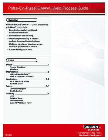
Pulse-On-Pulse GMAW Weld Process GuideOverviewPulse on Pulse GMAW – GTAW appearancewith GMAW productivity. Excellent control of heat inputon thinner materials. Eliminates in-line weaving. Optimum productivity in roboticand semi-automatic applications. Uniform, consistent beads on weldsin which appearance is critical. Easier training/Skill level.IndexDetails 1Process DescriptionWaveformOptimization 2Utilizing Pulse-On-Pulse When to use Pulse-On-Pulse Applications 3-41F, 2F and 3F Lap & Fillet1G Butt & GrooveSet-up 5-7Connection DiagramTroubleshootingGlossary 8IconsTechnical TermsProcedure NotesCustomer Assistance PolicyTE12.018
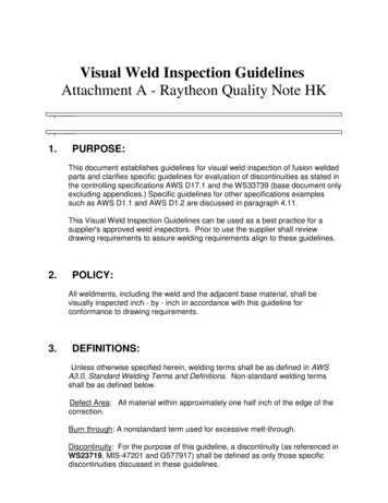
Pulse-On-Pulse GMAW Details1TE12.018Process DescriptionPulse on Pulse (GMAW-PP) is a Lincoln patentedprocess specifically designed for use in welding relativelythin (less than 1/4” thick) aluminum. It produces weldbeads with very consistent uniform ripple.In Pulse on Pulse modes, two distinct pulse types areused, instead of the single pulse type normally used inGMAW-P. A number of high energy pulses are used toobtain spray transfer and transfer metal across the arc.After a number of such pulses, depending on the wirefeed speed used, an identical number of low energypulses are performed. The Peak Current, BackgroundCurrent, and Frequency are identical for the high energyand low energy pulses. However, the details of the currentramp up and ramp down rates mean that a low energypulse contains less energy than a high energy pulse Inaddition to cooling the weld down, the major effect of thelow energy pulses is that they form a weld ripple. Sincethey occur at very regular time intervals, the weld beadobtained is very uniform with a very consistent ripplepattern. In fact, the bead has its best appearance if nooscillation of the welding gun (“whipping”) is used.HIGH HEATPULSESLOW HEATPULSESWaveformPEAKAMPSBACKGROUNDAMPSHIGH HEAT PULSESLOW HEAT PULSESTIME
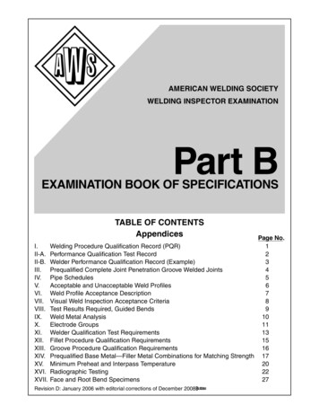
Pulse-On-Pulse GMAW Optimization2TE12.018Utilizing Pulse-On-Pulse ›Adjust WFS to: Control the welddeposition rate. Control heat input. 10 100›Adjust TRIM to: Control the arclength for amore stable process.-100T›Min.Adjust UltimArc to: Increase or decrease thespace between the“ripples.”Max.-10
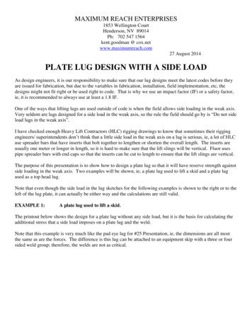
Pulse-On-Pulse GMAW Applications3TE12.0182F / PB Lap & Fillet1F / PA Lap & Fillet Use a 10-20 push angle. Use a 35 work angle. Position the electrodeapproximately oneelectrode diameter outsidethe joint favoring thebottom leg. For 14 ga applicationsposition the electrodedirectly in the joint orslightly favoring the topedge. May requiredecreased work angle.10 -2 0 35 FRONT Use a 10-20 push angle. Use a 40 work angle. Position the electrodeapproximately oneelectrode diameter outsidethe joint favoring thebottom leg.o10 - 20oFRONTSIDESIDEo4014 gaSIDESIDE100% Ar4043 Alloy0.035" dia.4043 Alloy3/64" dia.SIDEin1/4 in3/16 in10 ga12 ga14 ga16 gain/min600.0550.0400.0300.0220.0150.01/4 in3/16 in10 ga12 ga14 ga16 ga400.0340.0300.0250.0135.0100.0100% Ar100% Ar4043 Alloy0.035" dia.4043 Alloy3/64" dia.in1/4 in3/16 in10 ga12 ga14 ga16 gain/min600.0550.0400.0300.0220.0150.01/4 in3/16 in10 ga12 ga14 ga16 ga400.0340.0300.0250.0135.0100.0100% Ar5356 Alloy0.035" dia.in1/4 in3/16 in10 ga12 ga14 ga16 gain/min700.0670.0550.0400.0300.0225.05356 Alloy0.035" dia.in1/4 in3/16 in10 ga12 ga14 ga16 gain/min700.0670.0550.0400.0300.0225.05356 Alloy3/64" dia.1/4 in3/16 in10 ga12 ga14 ga16 ga500.0375.0300.0200.0175.0125.05356 Alloy3/64" dia.1/4 in3/16 in10 ga12 ga14 ga16 ga500.0375.0300.0200.0175.0125.0Trim and Ultimarc should be used at the nominal settings. Adjust to application settings.See Customer Assistance Policy and Disclaimer Notice on page 8.
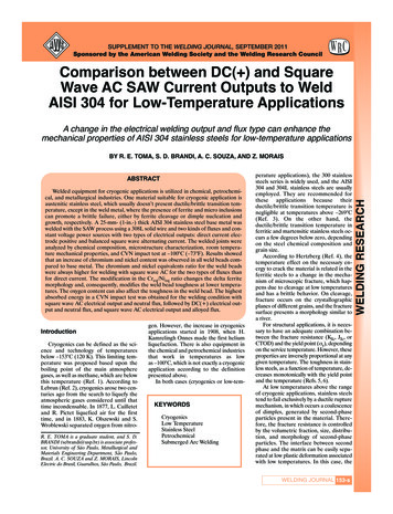
Pulse-On-Pulse GMAW Applications4TE12.0183F / PG Lap & Fillet1G / 2G Butt & Groove Use a 10 drag angle. Use a 30 work angle. Position the electrodeapproximately oneelectrode diameter outsidethe joint favoring thebottom leg. For 14 ga applicationsposition the electrodedirectly in the joint orslightly favoring the edge.30 Use a 10 drag angle. Use a 30 work angle. Position the electrodeapproximately oneelectrode diameter outsidethe joint favoring thebottom leg. For 14 ga applicationsposition the electrodedirectly in the joint orslightly favoring the edge.5 - 10 oTOPTOPTOPSIDE0 1014 gaoSIDESIDETOP100% Ar4043 Alloy0.035" dia.4043 Alloy3/64" dia.in1/4 in3/16 in10 ga12 ga14 ga16 gain/min600.0550.0400.0300.0220.0150.01/4 in3/16 in10 ga12 ga14 ga16 ga400.0340.0300.0250.0135.0100.0100% Ar100% Ar4043 Alloy0.035" dia.4043 Alloy3/64" dia.in1/4 in3/16 in10 ga12 ga14 ga16 gain/min600.0550.0400.0300.0220.0150.01/4 in3/16 in10 ga12 ga14 ga16 ga400.0340.0300.0250.0135.0100.0100% Ar5356 Alloy0.035" dia.in1/4 in3/16 in10 ga12 ga14 ga16 gain/min700.0670.0550.0400.0300.0225.05356 Alloy0.035" dia.in1/4 in3/16 in10 ga12 ga14 ga16 gain/min700.0670.0550.0400.0300.0225.05356 Alloy3/64" dia.1/4 in3/16 in10 ga12 ga14 ga16 ga500.0375.0300.0200.0175.0125.05356 Alloy3/64" dia.1/4 in3/16 in10 ga12 ga14 ga16 ga500.0375.0300.0200.0175.0125.0Trim and Ultimarc should be used at the nominal settings. Adjust to application settings.See Customer Assistance Policy and Disclaimer Notice on page 8.
Pulse-On-Pulse GMAW Set-Up5TE12.018Connection Diagram100% Ar
Pulse-On-Pulse GMAW heckVoltsContact Tipto WorkDistanceWire FeedSpeed?Gas CoverageSurfaceContaminatesPush AngleSpatterActionCheckProper FeedingTipVolts?SurfaceContaminantsContact Tipto WorkDistanceSurfaceContaminantsErratic ArcActionCheckGas CoveragePorosityActionCheck?Gas CoverageContact Tipto WorkDistancePush AngleArc ControlSmut / SootActionIncreaseDecreaseInspect & ReplaceImportant
Pulse-On-Pulse GMAW Set-Up7TE12.018TroubleshootingCheckVoltsWire FeedSpeedVoltsTravel SpeedPush AngleConcave BeadActionCheckWire FeedSpeedPush AngleUnder CutActionCheckTravel SpeedWire FeedSpeedBurn ThroughActionCheckTravel SpeedWire FeedSpeedVoltsTravel SpeedWire FeedSpeedVoltsPush AngleConvex BeadActionCheckPoor PenetrationActionIncreaseDecreaseInspect & ReplaceImportant
Pulse-On-Pulse GMAW Glossary8TE12.018IconsTTravel SpeedVoltsTrimSpatter (Minimal)SpatterArc LengthUnder CutBurn ThroughConvex BeadGasWire FeedSpeedTravel Speed(Slow)Travel Speed(Fast)PorosityConcave BeadWire TypeTorch NozzleVMaterialThicknessContact Tipto WorkDistanceControl KnobHigh HeatWire DiameterPush AngleGas CoveragePoor PenetrationSmut / Soot?Low HeatSurfaceContaminantsTechnical TermsGMAWGas metal arc welding including metal inert gas (MIG) and metal active gas (MAG) welding.PorosityGas entrapped in solidifying metal forms spherical or elongated pores in the weld.Push AngleThe angle at which the electrode leads the weld pool relative to the direction of travel.SynergicA mode of control which automatically selects a preprogrammed nominal voltage based on the wirefeed speed (WFS) set by the operator.Work AngleThe angle of the electrode, off perpendicular, relative to the work piece surface.Procedure NotesAll listed procedures are starting points and may The result of welding at higher travel speeds is arequire some adjustment depending on the specific tendency to produce more spatter, lessapplication.penetration, more undercut, and a less desirablebead shape. Depending on the limitations /Torch angle, electrode placement, contamination, requirements of the actual application, slowermill scale, joint fit up, and joint consistency are travel speeds and higher arc voltages may befactors that may require special consideration required.depending on the specific application.As the travel speed increases in fast followAt higher travel speeds, joint fit up, wire placement, applications (1/4” to 14 Gauge), a tighter and arcand contamination all become factors that are length must be maintained so that the puddlemore significant.properly follows the arc.Operators typicallyreduce the arc length control (Trim) to achieve this.At faster travel speeds, the bead-shape canbecome very convex (or ropy), and the weld will not“wet” well. There is a point at which the arc is set soshort that the arc will become unstable andstubbing will occur. This forms a limitation of justhow fast the travel speed can be raised.It is ultimately the responsibility of the end user toensure the proper weld deposition rate, beadprofile, and structural integrity of a given weldapplication.Customer Assistance PolicyThe business of The Lincoln Electric Company is manufacturing and selling high quality welding equipment, consumables, and cutting equipment. Our challengeis to meet the needs of our customer and to exceed their expectations. On occasion, purchasers may ask Lincoln Electric for advice or information about theiruse of our products. We respond to our customers based on the best information in our possession at that time. Lincoln Electric is not in a position to warrant orguarantee such advice, and assumes no liability, with respect to such information or advice. We expressly disclaim any warranty of any kind, including anywarranty of fitness for any customer’s particular purpose, with respect to such information or advice. As a matter of practical consideration, we also cannotassume any responsibility for updating or correcting any such information or advice once it has been given, nor does the provision of information or advicecreate, expand or alter any warranty with respect to the sale of our products.Lincoln Electric is a responsive manufacturer, but the selection and use of specific products sold by Lincoln Electric is solely within the control of, and remains thesole responsibility of the customer. Many variables beyond the control of Lincoln Electric affect the results obtained in applying these types of fabricationmethods and service requirement. Subject to change.This information is accurate to the best of our knowledge at the time of printing. Please refer to www.lincolnelectric.com for any updated information.
process specifically designed for use in welding relatively thin (less than 1/4” thick) aluminum. It produces weld beads with very consistent uniform ripple. In Pulse on Pulse modes, two distinct pulse types are used, instead of the single pulse type normally u