Transcription
SYSTEM CIRCUITS H2007 YARISELECTRICAL WIRING DIAGRAMSYSTEM CIRCUITSABS . . . . . . . . . . . . . . . . . . . . . . . . . . . . . . . . . . . . . . . . . . . . . . . . . . . . . . . . . . . . . . .Air Conditioning . . . . . . . . . . . . . . . . . . . . . . . . . . . . . . . . . . . . . . . . . . . . . . . . . . . .Audio System . . . . . . . . . . . . . . . . . . . . . . . . . . . . . . . . . . . . . . . . . . . . . . . . . . . . . .Back–Up Light . . . . . . . . . . . . . . . . . . . . . . . . . . . . . . . . . . . . . . . . . . . . . . . . . . . . . .Charging . . . . . . . . . . . . . . . . . . . . . . . . . . . . . . . . . . . . . . . . . . . . . . . . . . . . . . . . . . .Cigarette Lighter . . . . . . . . . . . . . . . . . . . . . . . . . . . . . . . . . . . . . . . . . . . . . . . . . . . .Combination Meter . . . . . . . . . . . . . . . . . . . . . . . . . . . . . . . . . . . . . . . . . . . . . . . . . .Cooling Fan . . . . . . . . . . . . . . . . . . . . . . . . . . . . . . . . . . . . . . . . . . . . . . . . . . . . . . . .Cruise Control . . . . . . . . . . . . . . . . . . . . . . . . . . . . . . . . . . . . . . . . . . . . . . . . . . . . . .Data Link Connector 3 . . . . . . . . . . . . . . . . . . . . . . . . . . . . . . . . . . . . . . . . . . . . . .Door Lock Control . . . . . . . . . . . . . . . . . . . . . . . . . . . . . . . . . . . . . . . . . . . . . . . . . .Electronically Controlled Transmission and A/T Indicator . . . . . . . . . . . . . .Engine Control . . . . . . . . . . . . . . . . . . . . . . . . . . . . . . . . . . . . . . . . . . . . . . . . . . . . .Engine Immobiliser System . . . . . . . . . . . . . . . . . . . . . . . . . . . . . . . . . . . . . . . . . .EPS . . . . . . . . . . . . . . . . . . . . . . . . . . . . . . . . . . . . . . . . . . . . . . . . . . . . . . . . . . . . . . . .Front Fog Light . . . . . . . . . . . . . . . . . . . . . . . . . . . . . . . . . . . . . . . . . . . . . . . . . . . . .Front Wiper and Washer . . . . . . . . . . . . . . . . . . . . . . . . . . . . . . . . . . . . . . . . . . . . .Headlight . . . . . . . . . . . . . . . . . . . . . . . . . . . . . . . . . . . . . . . . . . . . . . . . . . . . . . . . . .Horn . . . . . . . . . . . . . . . . . . . . . . . . . . . . . . . . . . . . . . . . . . . . . . . . . . . . . . . . . . . . . . .Ignition . . . . . . . . . . . . . . . . . . . . . . . . . . . . . . . . . . . . . . . . . . . . . . . . . . . . . . . . . . . .Illumination . . . . . . . . . . . . . . . . . . . . . . . . . . . . . . . . . . . . . . . . . . . . . . . . . . . . . . . .Interior Light . . . . . . . . . . . . . . . . . . . . . . . . . . . . . . . . . . . . . . . . . . . . . . . . . . . . . . .Key Reminder . . . . . . . . . . . . . . . . . . . . . . . . . . . . . . . . . . . . . . . . . . . . . . . . . . . . . .Light Reminder . . . . . . . . . . . . . . . . . . . . . . . . . . . . . . . . . . . . . . . . . . . . . . . . . . . . .Multiplex Communication System (CAN) . . . . . . . . . . . . . . . . . . . . . . . . . . . . . .Power Outlet . . . . . . . . . . . . . . . . . . . . . . . . . . . . . . . . . . . . . . . . . . . . . . . . . . . . . . .Power Source . . . . . . . . . . . . . . . . . . . . . . . . . . . . . . . . . . . . . . . . . . . . . . . . . . . . . .Power Window . . . . . . . . . . . . . . . . . . . . . . . . . . . . . . . . . . . . . . . . . . . . . . . . . . . . .Rear Window Defogger . . . . . . . . . . . . . . . . . . . . . . . . . . . . . . . . . . . . . . . . . . . . . .Rear Wiper and Washer . . . . . . . . . . . . . . . . . . . . . . . . . . . . . . . . . . . . . . . . . . . . .Remote Control Mirror . . . . . . . . . . . . . . . . . . . . . . . . . . . . . . . . . . . . . . . . . . . . . .Seat Belt Warning . . . . . . . . . . . . . . . . . . . . . . . . . . . . . . . . . . . . . . . . . . . . . . . . . . .Shift Lock . . . . . . . . . . . . . . . . . . . . . . . . . . . . . . . . . . . . . . . . . . . . . . . . . . . . . . . . . .SRS . . . . . . . . . . . . . . . . . . . . . . . . . . . . . . . . . . . . . . . . . . . . . . . . . . . . . . . . . . . . . . .Starting . . . . . . . . . . . . . . . . . . . . . . . . . . . . . . . . . . . . . . . . . . . . . . . . . . . . . . . . . . . .Stop Light . . . . . . . . . . . . . . . . . . . . . . . . . . . . . . . . . . . . . . . . . . . . . . . . . . . . . . . . . .Taillight . . . . . . . . . . . . . . . . . . . . . . . . . . . . . . . . . . . . . . . . . . . . . . . . . . . . . . . . . . . .Theft Deterrent . . . . . . . . . . . . . . . . . . . . . . . . . . . . . . . . . . . . . . . . . . . . . . . . . . . . .Turn Signal and Hazard Warning Light . . . . . . . . . . . . . . . . . . . . . . . . . . . . . . . .Wireless Door Lock Control . . . . . . . . . . . . . . . . . . . . . . . . . . . . . . . . . . . . . . . . 597414213420012419267YARIS (EM01V0U)
Power SourceB30A ABS2/VSC240A HTR SUB2B11E12130A HTR SUB150A EPS1212150A ABS1/VSC112230A RDI2W40A HTR1WC10Generator27. 5A ALT–S11D12B15A DOME121WBBB130A ST11 C1 A1 B22 BA27(B), A28(A), C30(C)Fusible Link Block60A MAIN120A ALT2L7. 5A ECU–B110A ETCS1210A HAZ1210A H–LP LH/H–LP LO LHBattery1210A H–LP RH/H–LP LO RH1268YARIS (EM01V0U)L
BBEFI Relay20A EFI110A EFI241A24AA1BB11210A HORN1215A AM2W11C12YACC 2WG4 AM1IG1 1GR5 AM2IG2 6PST2 7BIG2 RelayYGR3 AD24 AD2P5 AD4GR1 1BW4 1BW2 1BP3 1BD8Ignition SWW–BP14 AA2WLLA169YARIS (EM01V0U)
Power SourceBBYYWGGW2313 4B1WP8 4S7. 5A ACC2D43Fuse BlockD45ACC Cut RelayP115A CIG454F7. 5A ACCLGL7. 5A IGN18 AD4W44F7. 5A METGWL13ACCRA21Engine ControlModule70YARIS (EM01V0U)2B
B14GT–LP Relay10A TAIL( 1)( 1)( 1)( 1)( 1)( 1)( 1)7. 5A PANEL130A DEF( 1)DEF Relay10A ID/UP/MIR HTR21 1 : H/B, S/D 3 2 : Except 1 3 : Cold Area Spec. ,w/ Engine Immobiliser System,w/ ABS,w/ Rear Window Defogger,w/ Door Lock Control,w/ Daytime Running Light,w/ Remote Control Mirror,w/ Air Conditioning15A FR FOG7. 5A OBD225A D/LY14F10A STOP25A AM134F44M10A TAIL( 2)( 2)W( 2)132120A RL DOOR20A RR DOORB1LightControlSWT1OFFTailHeadT110IG 1 Relay5B1D4Headlamp Dimmer SW Assembly30A POWERPWR Relay310A ECU–IG125A WIPG( 2)15A WSH17 4E7 4M104E7. 5A PANEL2( 2)7. 5A PANEL1( 2)( 2)10A GAUGE15A RR WIPW–B2W–BG7. 5A A/C1 6AD1D271YARIS (EM01V0U)
Power Source: Parts LocationCodeSee Page46 (H/B)A21A27A2843, 46 (H/B)C3043, 48 (S/D)43, 46 (H/B)ASee Page47 (H/B)C1048 (S/D)BCodeCD443, 48 (S/D)49 (S/D)42, 47 (H/B)42, 49 (S/D)51 (H/B)53 (S/D)CodeD8D43D45: Relay BlocksCode1See Page24Relay Blocks (Relay Block Location)Engine Room R/B (Engine Compartment Left): Junction Block and Wire Harness ConnectorCodeSee PageJunction Block and Wire Harness (Connector Location)1A1B251C1D1E4B4E4F4G4M4S6AEngine Room Main Wire and Engine Room J/B (Engine Compartment Left)2430Engine Room Main Wire and Instrument Panel J/B (Lower Finish Panel)30Instrument Panel Wire and Instrument Panel J/B (Lower Finish Panel)30Engine Room Main Wire and Instrument Panel J/B (Lower Finish Panel)31Instrument Panel Wire and Instrument Panel J/B (Lower Finish Panel)40Instrument Panel Wire and J/B No.6 (Right Kick Panel): Connector Joining Wire Harness and Wire HarnessCodeAA1AA2AD2AD4See PageJoining Wire Harness and Wire Harness (Connector Location)62 (H/B)63 (S/D)62 (H/B)Engine Room Main Wire and Engine Room Main Wire (Instrument Panel Left)63 (S/D)62 (H/B)63 (S/D)62 (H/B)Engine Room Main Wire and Instrument Panel Wire (Instrument Panel Left)63 (S/D): Ground PointsCodeA1D1D2See Page60 (H/B)61 (S/D)62 (H/B)63 (S/D)62 (H/B)63 (S/D)Ground Points LocationLeft Suspension TowerLeft Kick PanelRight Kick Panel72YARIS (EM01V0U)See Page51 (H/B)53 (S/D)45, 51 (H/B)45, 53 (S/D)51 (H/B)53 (S/D)
Memo73YARIS (EM01V0U)
Starting(BAT)30AST2W1152STRelay3111VB115BRW12( 1)B14( 2)13A25Junction Connector9 CA1VWBR( 1)10 CA11AA16Clutch Start SW11 B5BLY( 2)C1(A), C15(B)StarterPC27Park/NeutralPosition SWNGR4( 1)BMW–B210 CA2BatteryGR213A25JunctionConnector( 1)Y( 2)A174YARIS (EM01V0U)Y
1 : A/T 2 : M/T(BAT)15AAM25 AM22IG2BST2 7B1 1BGRD8Ignition SWB14 A1STSWSTASTAR48 AD44Diode (Starter)252 BOA21(A), C20(B)Engine Control ModuleGRB9 AD44 AD2SBOBR8 CA1O12 AA21 AD45 AA2OBR75D36Junction ConnectorGR6Y10 AD413 AA2Y75YARIS (EM01V0U)
Starting: Parts LocationCodeSee Page50 (H/B)A16A2152 (S/D)46 (H/B)A48 (S/D)46 (H/B)A25C148 (S/D)A47 (H/B)CodeSee PageC1AC15BC20BC2749 (S/D)47 (H/B)49 (S/D)47 (H/B)49 (S/D)47 (H/B)CodeD8D36D4449 (S/D): Relay BlocksCode1See Page24Relay Blocks (Relay Block Location)Engine Room R/B (Engine Compartment Left): Junction Block and Wire Harness ConnectorCode1BSee Page25Junction Block and Wire Harness (Connector Location)Engine Room Main Wire and Engine Room J/B (Engine Compartment Left): Connector Joining Wire Harness and Wire HarnessCodeAA2AD2AD4CA1CA2See Page62 (H/B)63 (S/D)Joining Wire Harness and Wire Harness (Connector Location)Engine Room Main Wire and Engine Room Main Wire (Instrument Panel Left)62 (H/B)63 (S/D)62 (H/B)Engine Room Main Wire and Instrument Panel Wire (Instrument Panel Left)63 (S/D)60 (H/B)61 (S/D)60 (H/B)Engine Wire and Engine Room Main Wire (Engine Compartment Left)61 (S/D): Ground PointsCodeA1See Page60 (H/B)61 (S/D)Ground Points LocationLeft Suspension Tower76YARIS (EM01V0U)See Page51 (H/B)53 (S/D)51 (H/B)53 (S/D)51 (H/B)53 (S/D)
Memo77YARIS (EM01V0U)
Charging(BAT)10A GAUGE 1 : w/ Daytime Running Light 2 : w/o Daytime Running Light(IG)7. 5A MET7. 5A ALT–S(IG)2PGCharge9G501 AD1(A), D2(B), D76(C)Combination MeterCHG–19 4BBWD9Running Light Relay1 4M( 1)24ALTC20Engine Control ModuleALTE9A/C Amplifier1D39JunctionConnector1 B (H/B)1 C (S/D)7 AE11314SB( 1)( 2)L1 CA1GLL15 AD3W5 CA1PP15 CA1( 1)P12L7 AA2BP4 CA1120A ALT1 B3 A1 ABMSC9(A), C10(B)GeneratorBatteryC30Fusible Link BlockL1IC Regulator78YARIS (EM01V0U)4 A2 ALIG
: Parts LocationCodeC9See PageAC10Code47 (H/B)C3049 (S/D)47 (H/B)B49 (S/D)47 (H/B)C2049 (S/D)See PageAD2B53 (S/D)51 (H/B)D3951 (H/B)53 (S/D)See PageD942, 49 (S/D)D1D9Code42, 47 (H/B)D7651 (H/B)51 (H/B)53 (S/D)CE953 (S/D)50 (H/B)52 (S/D): Relay BlocksCode1See Page24Relay Blocks (Relay Block Location)Engine Room R/B (Engine Compartment Left): Junction Block and Wire Harness ConnectorCodeSee PageJunction Block and Wire Harness (Connector Location)4B30Engine Room Main Wire and Instrument Panel J/B (Lower Finish Panel)4M31Instrument Panel Wire and Instrument Panel J/B (Lower Finish Panel): Connector Joining Wire Harness and Wire HarnessCodeAA2AD3AE1CA1See Page62 (H/B)63 (S/D)62 (H/B)63 (S/D)62 (H/B)63 (S/D)60 (H/B)61 (S/D)Joining Wire Harness and Wire Harness (Connector Location)Engine Room Main Wire and Engine Room Main Wire (Instrument Panel Left)Engine Room Main Wire and Instrument Panel Wire (Instrument Panel Left)Engine Room Main Wire and Instrument Panel No.2 Wire (Instrument Panel Left)Engine Wire and Engine Room Main Wire (Engine Compartment Left)79YARIS (EM01V0U)
Ignition(BAT)GR15AAM2D8Ignition SW25 AM2IG2 6PST2RR11 CA1GR14 AA2PR4 AD2P5 AD42 1B1 1B4 1BRIG2RelayW–B3 1BA180YARIS (EM01V0U)C25Noise Filter1
RRR1C11Ignition Coil(No. 243OW–BYW–BGLW–BYYW–BW–BYW–BLGGNDY BY BC14Ignition Coil(No. 4)W BC13Ignition Coil(No. 3)W–B BC12Ignition Coil(No. 2)RLGRBRLG85IGT18184IGF1IGT283IGT382IGT4C20Engine Control ModuleC181YARIS (EM01V0U)
Ignition: Parts LocationCodeSee Page47 (H/B)C11C1349 (S/D)C1447 (H/B)C1249 (S/D)C13CodeC2047 (H/B)See Page49 (S/D)47 (H/B)49 (S/D)47 (H/B)CodeC25D849 (S/D): Junction Block and Wire Harness ConnectorCode1BSee Page25Junction Block and Wire Harness (Connector Location)Engine Room Main Wire and Engine Room J/B (Engine Compartment Left): Connector Joining Wire Harness and Wire HarnessCodeAA2AD2AD4CA1See Page62 (H/B)63 (S/D)Joining Wire Harness and Wire Harness (Connector Location)Engine Room Main Wire and Engine Room Main Wire (Instrument Panel Left)62 (H/B)63 (S/D)62 (H/B)Engine Room Main Wire and Instrument Panel Wire (Instrument Panel Left)63 (S/D)60 (H/B)61 (S/D)Engine Wire and Engine Room Main Wire (Engine Compartment Left): Ground PointsCodeA1C1See Page60 (H/B)61 (S/D)60 (H/B)61 (S/D)Ground Points LocationLeft Suspension TowerEngine Block Left82YARIS (EM01V0U)See Page47 (H/B)49 (S/D)51 (H/B)53 (S/D)
Memo83YARIS (EM01V0U)
Engine Control(BAT)(BAT)15AAM220AEFI22EFIRelay5 AM2IG2RelayIG2 6BW–BGRW–B2 1B4 1BD8Ignition SW1 1B14 AA2P3 1BGR2 1AGR3 1AR4 1AP1 1AYST24 AD25 AD4P21C7Fuel Injector (No. 4)C6Fuel Injector (No. 3)RBR212LPC5Fuel Injector (No. 2)1GRSB2C4Fuel Injector (No. 1)1RLGRP11 CA1PGRSBGRBW–BW–BYA184YARIS (EM01V0U)
(IG)(BAT)7. 5AIGN10ASTOP18 4B9 4B5 4E 11 4BB27 4BPC/OPNRelay328 4ABG36 A# 10108 BMRELBATT44 A20 AY# 20107 BSTPGR# 30106 BGR# 40105 BPIGSW28 ALFC7 AR535 AST1–VMPump4J5Fuel Suction Pump andGage AssemblyA21(A), C20(B)Engine Control Module1Y4SBBVRPA13Stop Lamp SWW–B12 AD4LPGRSBGRBBBBW–BYJ185YARIS (EM01V0U)
Engine Control(BAT)(BAT)15ADOME10AETCS8 4S14L121GRD45ACC Cut RelayP13 4BPW3L2GIgnition SWPark/Neutral Position SW (A/T)Clutch Start SW (M/T)1C19Engine Coolant Temp. Sensor224 AA296 B97 B3 AACCR42 ABVCPP70 BETHWPPMP71 BEPPM94 BOVPMP B21 AB13 ASTALSTARVSTSWA21(A), C20(B)Engine Control ModuleGR48 ALBR52 BPO14 AGB18 AD415 CA216 CA217 CA2THW BMMPMP34 A14 CA26 AJ15 AJ1BRBR7 AJ15 AA1BR3 AA1VO9 AA1OL10 AA1L6 AA1V10AEFI2B2VBP114 AJ11 AJ12 AJ13 AJ1BBB4AA1J25Canister Pump MVent ValveCanister Pressure SensorLeak Detection PumpBC286YARIS (EM01V0U)
W10ATAILT–LPRelay( 1)13D4Headlamp Dimmer SW AssemblyB( 1)110ATAIL15 4BB1T1OFFLightControlSWTailHeadT110GG10 4EB1( 2)1 4G 1 : H/B, S/D 3 2 : Except 1 3 : Cold Area Spec. ,w/ Engine Immobiliser System,w/ ABS,w/ Rear Window Defogger,w/ Door Lock Control,w/ Daytime Running Light,w/ Remote Control Mirror,w/ Air Conditioning( 2)( 2)( 1)( 1)4 4M120A ALTA28FusibleLink Block(BAT)A21(A), C20(B)Engine Control Module31 AELS BIMIIMOPRGEOMTHA49 B9 A8 AD417 AD47 AD465 BE2G116 BVG118 BETHA88 BPLGGROLBR10 AO11 AW2 A4235THAE2GVGOBR131211EFIOEFIIC3VSV (Purge)WB12EGNDE2 BD23Transponder Key ECUC26Mass Air Flow MeterBV1BV1AA2V12CA1B9AA2B5AD5VBBBB87YARIS (EM01V0U)
OGLGYOLGFAN NO. 2 RelayWIgnition CoilsFAN NO. 1 RelayEngine Control85 B84 B83 B82 B81 B21 A22 AFANFAN2A1A HT1B BBC23Air Fuel Ratio Sensor(Bank 1 Sensor 1)LGGR4 CA2GR3A1A 5 CA24 AD53 AD5GR4A1A–EX1B87 B14HT1BE2 BOX1B23W1HA1A247 BA21(A), C20(B)Engine Control ModuleLG112 BLG(Shielded)G113 BIGF1LGA1A–109 BIGT4BHA1AIGT3D28Oxygen Sensor (Bank 1 Sensor 2)IGT2VIGT1WB(Shielded)B88YARIS (EM01V0U)
(BAT)30ADEF211 4MA20Accelerator Position SensorDEFRelay10AID/UP/MIR HTRVPA2EPA2VCPAVPAEPA132465VVCP2LBRBRG58 A56 A60 A57 A55 A59 AVW8 AD333 AELS3KNK1NE VCPAVPAEPANE–G2 121 B99 BBB2 CP1W1 CP1(Shielded)P122 B2 AD522C18Camshaft PositionSensor1 AD51C2Crankshaft PositionSensor2P1Knock Control Sensor(Bank 1)W(Shielded)EPA2PG3 CA2W2 CA2EKNK111 BR(Shielded)110 BG(Shielded)64 BVPA2LOX1BVCP2(Shielded)A21(A), C20(B)Engine Control Module1W(Shielded)1WBR(Shielded)C189YARIS (EM01V0U)
Engine ControlC17Throttle Body AssemblyM–2142 B41 BBRRM 4GW67 BVTA2YV91 BVTA6(Shielded)VC5GRE23ME01E01E04E03ALT43 B45 B46 B86 B50 BPE1104 BW–B44 BW–BE0232 AGE01W–BECM–BRRC24Camshaft Timing Oil Control ValveBR1123 BM BROC1–100 BVTA2A21(A), C20(B)Engine Control Module63 BWOC1 VTA1BVCTA114 BW–BETA115 B3M2C9GeneratorA1C190YARIS (EM01V0U)C2
A21(A), C20(B)Engine Control ModuleCANLCANHLB15 AD417 AD3CANLCANH2213L16 AD424 AD16Airbag Sensor AssemblyCenterB26 4BW41 AWW49 AW23 4BSPD8 AVPTACH15 ALGTC27 A1519849TACD15Data Link Connector 3SBD41JunctionConnector11YTC22W138 4CLGP12 4DB13 AD42211187D42JunctionConnectorBGWSB91YARIS (EM01V0U)
Engine Control(BAT)(IG)(IG)7. 5AMET7. 5AECU–B10AECU–IG21 4M24 4BLB30 4BL1B2 4S25 AA2L16A25JunctionConnector20D1(A), D2(B), D76(C)Combination Meter2 AB1 AB11 CA25V ICSISE216 A17 ABRSBPW–BW–B24 A6 AA223 AA2W–B21 A13 CA2P20 AWI/FGI/F12 CA2PCAN ControllerPCPUB11 AD3GWSBD392YARIS (EM01V0U)A1C21Speed SensorTachometerMalfunctionIndicator LampIG 3CAN I/F4 B (H/B)4 C (S/D)Speedometer1
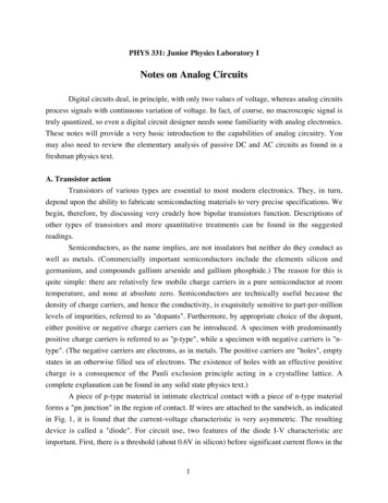
System Outline1. Electronic Fuel InjectionIt controls to have appropriate fuel injection according to the basic injection time. The basic injection time is calculated to fitthe engine condition and is corrected with signals from various sensors.2. Electronic Spark AdvanceAppropriate ignition is conducted according to the basic ignition timing which is calculated to fit the engine condition aftercorrecting it with signals from various sensors.3. Electronic Throttle Control System–intelligentIt controls to have appropriate throttle opening according to the throttle opening calculated to fit the engine condition aftercorrecting it with signals from various sensors.4. Variable Valve Timing–intelligentIt improves engine output, reduces exhaust gas and improves fuel consumption by varying the phase of the intake camshaftin accordance with the engine condition.5. Electric Fan ControlIt controls the switching ON/OFF and fan speed of the cooling fan according to the coolant temperature and air conditioner’scondition.6. Fuel Pump ControlIt turns ON/OFF the fuel pump according to the starter signal and engine speed signal. It stops the fuel pump operationaccording to signals from the airbag sensor assembly center.7. Air Conditioning Cut–Off ControlIt reduces load of the air conditioner’s compressor in acceleration in order to secure the drivability.8. Canister Purge ControlIt controls the purge flow volume of the canister according to the coolant temperature and driving condition.9. Cranking Hold ControlIt continues to supply electricity to the starter between the start of cranking and the engine start in order to prevent theengine start failure by the key’s switching off just before the engine’s complete explosion.10. Oxygen Sensor ControlIt switches ON/OFF the oxygen sensor according to the coolant temperature and driving condition.11. DiagnosisIt realizes accurate and detailed diagnosis of a failure such as calling the SAE specified diagnosis code data and active testby using the diagnosis tool.12. Fail–SafeWhen the engine control module detects abnormality in signals of the sensors, it stops or continues to control the engine byusing the standard values in the engine control module.93YARIS (EM01V0U)
Engine Control: Parts LocationCodeSee PageA1350 (H/B)46 (H/B)46 (H/B)A2548 (S/D)C2043, 46 (H/B)A2847 (H/B)C247 (H/B)C347 (H/B)47 (H/B)C549 (S/D)47 (H/B)C649 (S/D)47 (H/B)C749 (S/D)47 (H/B)C949 (S/D)49 (S/D)49 (S/D)BD4D8D15D761See Page24J551 (H/B)1A51 (H/B)51 (H/B)53 (S/D)51 (H/B)P153 (S/D)51 (H/B)Relay Blocks (Relay Block Location)Junction Block and Wire Harness (Connector Location)Engine Room Main Wire and Engine Room J/B (Engine Compartment Left)4A30Floor Wire and Instrument Panel J/B (Lower Finish Panel)4B30Engine Room Main Wire and Instrument Panel J/B (Lower Finish Panel)30Instrument Panel Wire and Instrument Panel J/B (Lower Finish Panel)30Engine Room Main Wire and Instrument Panel J/B (Lower Finish Panel)31Instrument Panel Wire and Instrument Panel J/B (Lower Finish Panel)4C4D4E4G4M4S94YARIS (EM01V0U)53 (S/D)51 (H/B)53 (S/D)53 (S/D)57 (3–Door)57 (3–Door)59 (4–Door)251B51 (H/B)55 (5–Door)J25Engine Room R/B (Engine Compartment Left)See Page53 (S/D)59 (4–Door)53 (S/D): Junction Block and Wire Harness ConnectorCode51 (H/B)55 (5–Door): Relay BlocksCode53 (S/D)C47 (H/B)D251 (H/B)D4547 (H/B)A53 (S/D)D4247 (H/B)D151 (H/B)D4149 (S/D)C2649 (S/D)49 (S/D)49 (S/D)53 (S/D)D2847 (H/B)47 (H/B)C2449 (S/D)C449 (S/D)C2349 (S/D)51 (H/B)D2347 (H/B)C2143, 48 (S/D)53 (S/D)D1649 (S/D)BSee PageD1547 (H/B)C1948 (S/D)Code49 (S/D)C1852 (S/D)ASee Page47 (H/B)C1752 (S/D)A20A21Code50 (H/B)47 (H/B)49 (S/D)
: Connector Joining Wire Harness and Wire HarnessCodeAA1AA2AD2AD3AD4AD5AJ1CA1CA2CP1See PageJoining Wire Harness and Wire Harness (Connector Location)62 (H/B)63 (S/D)62 (H/B)Engine Room Main Wire and Engine Room Main Wire (Instrument Panel Left)63 (S/D)62 (H/B)63 (S/D)62 (H/B)63 (S/D)62 (H/B)Engine Room Main Wire and Instrument Panel Wire (Instrument Panel Left)63 (S/D)62 (H/B)63 (S/D)62 (H/B)63 (S/D)Engine Room Main Wire and Floor Wire (Instrument Panel Left)60 (H/B)61 (S/D)60 (H/B)Engine Wire and Engine Room Main Wire (Engine Compartment Left)61 (S/D)60 (H/B)61 (S/D)Engine Wire and Sensor Wire (Engine Compartment Center): Ground PointsCodeA1C1C2D3See Page60 (H/B)61 (S/D)Left Suspension Tower60 (H/B)61 (S/D)60 (H/B)Engine Block Left61 (S/D)62 (H/B)63 (S/D)64 (5–Door)J1Ground Points Location65 (3–Door)66 (4–Door)Instrument Panel Reinforcement LeftRight Rear Quarter PanelLower Back Panel Right95YARIS (EM01V0U)
ECT and A/T Indicator(IG)(BAT)20AEFI(BAT)7. 5AIGN10ASTOP227 4B 18 4BPark/Neutral Position SW9 4BB32RPEFIRelay1 1A4 1A3 1A2 1A36 AST1–A21(A), C20(B)Engine Control ModuleBR35 AO1G4YGRW–BBYA13Stop Lamp SW52 B48 ASTARSTPW–B20 AYBATT2 AB B1 AB B244 AGRMREL28 ARIGSWSTAA196YARIS (EM01V0U)
2VCP2VPA2EPA2VCPAVPAEPA132465NT LBRBRG125 BTHWW97 B58 A56 A60 A57 A55 A59 AGLBP296 BETHW1C29Speed Sensor (Turbine)C19Engine Coolant Temp. SensorP1A20Accelerator Position Sensor124 BNT–VCP2VPA2EPA2VCPAVPAEPAA21(A), C20(B)Engine Control ModuleW–BE0386 BW–BE0446 BW–BE0145 BBRME0143 BWP104 BBRE1E0244 BC2Crankshaft PositionSensorL(Shielded)1EC32 ABNE–121 BW–BNE 122 BBR2C1A1C1C297YARIS (EM01V0U)
ECT and A/T IndicatorA21(A), C20(B)Engine Control ModuleCANLCANH41 AL49 AW23 4BSPD8 AVLGTACH15 APTC27 A26 4B16 AD415 AD4L2211SB9TACD15Data Link Connector 3YTC4W13158 4CLGP12 4DW13 GWSB98YARIS (EM01V0U)
(BAT)(IG)10AETCS10AGAUGEG219 4B21 CA1RBGPLRLNLDL2LLL619738L3 A73 B53 B54 B55 B74 B56 BPRN2LD BMS1S279 B78 BSLU 77 BSLT 76 BSLT–75 BST80 BTHO172 BLVGRSLU–57 BSBRA21(A), C20(B)Engine Control ModuleGR24 AA2ETHO14 CA1LGRC27Park/Neutral Position SW1ODMS26 A95 BOLB14 AD32 AD36E29NSSDTransmissionControl SWAT3D22Shift Lock Control ECULTHOO1STOGRY2SLT–O8SLT Y3SLU–GRWG9SLU (H/B)SL(S/D)GBO4S2BR10S1LG5WPLSB22 AA23C28ElectronicallyControlled TransmissionSolenoidGGWWSBSB99YARIS (EM01V0U)
ECT and A/T Indicator(BAT)(IG)(IG)7. 5AECU–B7. 5AMET10AECU–IG21 4M24 4BLB11625 AA2A25JunctionConnectorBLB2030 4B11 CA2L2 4SB(S/D)1SILCPU12 CA213 CA2PW–B23 AA22021241617WBRSBPW–BI/FGI/F6 AA2PTachometerSpeedometerCAN ControllerCAN I/FSE2W–BLED Driver3P(S/D)(S/D)2D(S/D)N(S/D)(S/D)5V IC(S/D)PRIG 11 AD3GWSBD3100YARIS (EM01V0U)A1C21Speed Sensor(S/D)(S/D)(S/D)(S/D)D1Combination Meter1(S/D)2
: Parts LocationCodeSee Page50 (H/B)A13A21C2050 (H/B)52 (S/D)48 (S/D)C2746 (H/B)A2548 (S/D)C2847 (H/B)C249 (S/D)C19C2947 (H/B)49 (S/D)BC2146 (H/B)ASee PageC1952 (S/D)A20Code47 (H/B)49 (S/D)47 (H/B)49 (S/D)47 (H/B)49 (S/D)47 (H/B)49 (S/D)47 (H/B)CodeD1D15D22D41D42See Page51 (H/B)53 (S/D)51 (H/B)53 (S/D)51 (H/B)53 (S/D)51 (H/B)53 (S/D)51 (H/B)53 (S/D)49 (S/D): Relay BlocksCode1See Page24Relay Blocks (Relay Block Location)Engine Room R/B (Engine Compartment Left): Junction Block and Wire Harness ConnectorCodeSee PageJunction Block and Wire Harness (Connector Location)1A25Engine Room Main Wire and Engine Room J/B (Engine Compartment Left)4B30Engine Room Main Wire and Instrument Panel J/B (Lower Finish Panel)4C4D4M4S30Instrument Panel Wire and Instrument Panel J/B (Lower Finish Panel)31: Connector Joining Wire Harness and Wire HarnessCodeAA2AD3AD4CA1CA2See Page62 (H/B)63 (S/D)Joining Wire Harness and Wire Harness (Connector Location)Engine Room Main Wire and Engine Room Main Wire (Instrument Panel Left)62 (H/B)63 (S/D)62 (H/B)Engine Room Main Wire and Instrument Panel Wire (Instrument Panel Left)63 (S/D)60 (H/B)61 (S/D)60 (H/B)Engine Wire and Engine Room Main Wire (Engine Compartment Left)61 (S/D): Ground PointsCodeA1C1C2D3See Page60 (H/B)61 (S/D)Ground Points LocationLeft Suspension Tower60 (H/B)61 (S/D)60 (H/B)Engine Block Left61 (S/D)62 (H/B)63 (S/D)Instrument Panel Reinforcement Left101YARIS (EM01V0U)
Cruise Control(IG)(BAT)20AEFI(BAT)7. 5AIGN10ASTOP29 4B27 4B 18 4BB32RPEFIRelay1 1A4 1A3 1A2 1A1G4YGRW–BBYA13Stop Lamp SW35 A36 AST1–A21(A), C20(B)Engine Control ModuleSTPW–BYBATT20 AB B2 AB B21 AGRMREL44 ARIGSW28 AA1102YARIS (EM01V0U)
A20Accelerator Position Sensor5GEPA6RVPA4BVCPA2BREPA23LVPA21WVCP258 A56 A60 A57 A55 A59 AVCP2VPA2EPA2VCPAVPAEPAA21(A), C20(B)Engine Control ModuleE0386 BW–BE0446 BW–BE0145 BW–BME0143 BBR104 BBRE1E0244 BBEC32 AW–BPTACH15 ALGTC27 A23 4BPLG12 4D139TCW13 AD4TACD15Data Link Connector 3A1C1C2103YARIS (EM01V0U)
Cruise Control(BAT)10AETCS21GRC17Throttle Body AssemblyE23VC5VTAVTA2M M–6421R42 B41 BBRG(Shielded)GR67 BYW91 BGRV24 AA2VCTA114 BVTA1VTA2M CCS40 AA21(A), C20(B)Engine Control Module63 BM–GE01SPDCANLCANHL6 AD426 4B16 AD415 AD4LW41 AV49 AL8 ALETA BM115 BW3 A1542211ECC4 B7D34JunctionConnectorD3(A), V1(B)CCS SpiralCable3 BMAINY1 AWBR2 ASB8 4C2211187BR6 RES6 RGCANCELWBR13 CA1V1(B)Cruise Control SWSBC1104YARIS (EM01V0U)
(IG)(IG)10AGAUGE10AECU–IG19 4B24 4BBBG(M/T)(A/T)1621(M/T)A29Cruise ControlClutch SWC27Park/Neutral Position SWA25JunctionConnector1221 CA1D7G(A/T)L14CA1L(M/T)(A/T)LA21(A), C20(B)Engine Control Module56 BDB(A/T)Y(A/T)6OTHOE2OGRETHO95 B1STYGRG2SLT–THO172 B(A/T)W8SLT ST80 B(A/T)G3SLU–SLT–75 B(A/T)(A/T)OPSLT 76 B9SLBRBW4S2SLU–77 B(A/T)L10S1LG5SLU 57 B(A/T)SBS278 B(A/T)S179 BC28ElectronicallyControlled TransmissionSolenoidGGWWSBSB105YARIS (EM01V0U)
Cruise Control(BAT)(IG)7. 5AECU–B(IG)7. 5AMET10AECU–IG21 4M24 4BLB11625 AA2A25JunctionConnectorBLB2030 4B11 CA2D1Combination Meter2BL2 4S1IG SICRUISELED DriverCPU12 CA213 CA2PW–B23 AA22021241617WBRSBPW–BI/FGI/F6 AA2PCAN ControllerCAN I/FSE2W–B3P5V IC11 AD3GWSBD3106YARIS (EM01V0U)A1C21Speed Sensor1
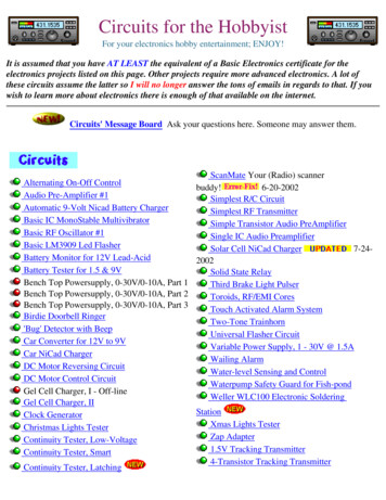
System OutlineThe cruise control system is a constant vehicle speed controller in which control of the switch on the instrument panel makesit possible to automatically adjust the opening of the engine throttle valve without depressing of the accel pedal.1. Set OperationWhen the CRUISE SW is turned on and the SET SW is pushed with the vehicle speed within the set limit (Approx. 40 km/h,25 mph to 200 km/h, 124 mph), a signal is input to TERMINAL CCS of the engine control module, and the vehicle speed atthe time the SET SW is released is memorized in the ECU as the set speed.2. Set Speed ControlDuring cruise control driving, the ECU compares the set speed memorized in the ECU with the actual vehicle speed inputinto TERMINAL SPD of the engine control module from the combination meter, and controls the throttle body assembly tomaintain the set speed.When the actual speed is lower than the set speed, the ECU causes the current to the throttle control motor to flow fromTERMINAL M of the engine control module to TERMINAL 2 of the throttle body assembly to TERMINAL 1 to TERMINALM– of the engine control module. As a result, the motor in the throttle control motor is rotated to open the throttle valve toincrease the vehicle speed. When the actual driving speed is higher than the set speed, the current to the throttle bodyassembly flows from TERMINAL M– of the ECU to TERMINAL 1 of the throttle control motor to TERMINAL 2 to TERMINALM of the engine control module.This causes the motor in the throttle body assembly to rotate to close the throttle valve to decrease the vehicle speed.3. Coast ControlDuring cruise control driving, while the –SET SW is on, the throttle control motor is rotated to close the throttle valve anddecrease the driving speed. The vehicle speed when the –SET SW is turned off is memorized, and the vehicle continues atthe new set speed.4. Accel ControlDuring cruise control driving, while the RES SW is turned on, the throttle control motor is rotated to open the throttle valveand increase the driving speed.The vehicle speed when the RES SW is turned off is memorized and the vehicle continues at the new set speed.5. Resume ControlIf the vehicle speed is approximately 40 km/h (25 mph) or above after canceling the set speed with the CANCEL SW,pushing the RES SW will cause the vehicle to resume the speed set before the cancellation.6. Manual Cancel MechanismIf any of the following signals is input during cruise control travelling, the cruise control is cancelled. Depressing the clutch pedal (Cruise control clutch SW off). ”Signal is not input to TERMINAL D of the ECU” (M/T) Placing the shift lever to positions except ”D” position (Park/Neutral position SW except ”D” position) (A/T) Pushing the CANCEL SW (CANCEL SW on). ”Signal input to TERMINAL CCS of the ECU” Pushing the CRUISE SW off ”signal input to TERMINAL CCS of the ECU”. Depressing the brake pedal (Stop light SW on)7. Tap–Up Control FunctionWhen the difference between the actual vehicle speed and the set speed is less than 5 km/h (3 mph), the set speed can beincreased 1.6 km/h (1 mph) each time by operating the RES SW quickly within 0.6 seconds.8. Tap–Down Control FunctionWhen the difference between the actual vehicle speed and the set speed is less than 5 km/h (3 mph), the set speed can belowered 1.6 km/h (1 mph) each time by operating the –SET SW quickly within 0.6 seconds.9. Auto Cancel FunctionA) If any of the following operating conditions occurs during cruise control operation, the set speed is erased and the cruisecontrol is released, (CRUISE SW turns off).When this occurs, the ignition SW must be turned off once before the CRUISE SW will turn on. When abnormality is found in the stop light SW input circuit. When abnormality is found in the cancel circuit.B) If any of the following operating conditions occurs during cruise control operation, the set speed is erased and the cruisecontrol is released. (CRUISE SW turn off).When this occurs, the cancel state is cleared as the CRUISE SW will turn on again. When abnormality is found in electronic throttle parts. Open circuit in the stop light SW. Momentary interruption of vehicle speed signal. Short circuit in the stop light SW.107YARIS (EM01V0U)
Cruise Control10. Overdrive Control FunctionThe overdriv
68 YARIS (EM01V0U) Power Source Battery 1 2 30A RDI 1 2 1 1E 12 40A HTR 12 50A ABS1/VSC