Transcription
JOURNAL OF RESEARCH of the National Bureau of Standards-C. Engineering and InstrumentationVol. 67C, No. 3, July- September 1963Relation of Emittance to Other Optical Properties *J. C. Richmond(March 4, 19G3)An equation was derived relating t he normal spcctral e mitta nce of a n optically in homogeneous, partiall y trans mitting coating applied over an opaque subs trate t o t he t hi ckn csan d optical propert ies of t he coating a nd the reflectance of thc s ubstrate at th c coaLin gSLI bst rate interface.I. IntroductionThe 45 0 to 0 0 luminous daylight r eflectance of a composite specimen com prisin g a parLiall:\'transparent, spectrally nonselective, ligh t-scattering coating applied to a completely opaque(nontransmitting) substrate, can be compu ted from th e reflecta.nce of the substrate, the thi ckness of t h e coaLing and the r eflectivity an d coefficien t of scatter of the coatin g material. Th eequaLions derived [01' th ese condi tions h ave been found by experience [1 , 2)1 to be of considerablepraeLical usefulness, even though sever al factors ar e known to exist in real m aterials that wer eno t consid ered in th e derivation . For instance, porcelain enamels an d glossy paints h avesignificant sp ecular r efl ectance at lhe coatin g-air in terface, and no r ea'! coating is truly spectrallynonselective.Th e optical properties of a material vary with wavelength , but in the derivation of Lh eequations r efened to above, they ar e consid ered to be independent of wavelength over the rathernarrow wav elength band encompassin g visible ligh t. Th e condition of s pectral nonselectivityis m et sufficiently well by a number o[ materials to permi t use of the pertinent equations with buta sin gle se t o[ optical properti es 1'01' vi ible li gh t. Over th e enormously wid er ran ge of wavelengLhs within which th e emission and absorp tion of r adiant en ergy are importan t, few if anymateri als are sufficiently nonselective lo p ermit use of the pertinen t equation with a sin gleset of optical proper Lies applicable Lo all wfLvelengths . H ence t h e optical properties as fl,fun ction of wavelength ar e r equired for computation of wide-range sp ectral reHectance oremi ttan ce of such composite specim ens .Th e present stud y was und er taken to derive an equaLion relatin g th e s pecLral reflec Lan ce(01' emi ttan ce) o[ a composite sp ecim en comprised of a par tially tr ansmittin g, light-scatterin gcoating applied to a completely opaque (nontransmittin g) substmte, from th e thickn ess ofth e cOfLLillg a nd tIle spectr al optical proper ties of th e coating and substm te.2. Review of the LiteratureTh e r elationship b etween the thickness and reflectance of a layer of light-scatterin g materials as a function of t h e optical constants of the material was developed by Kub elka andMunI,;: [3]. Judd [1] develop ed gr aphical methods for th e solution of the Kubelka-Munkequation, and d emonstmted that i t was useful in studying real materials which d epartedsom ewhat from the ideal material postulated in development of t h e equfLtion . Kubclka [4]derived more exact equations in a form that was cap able of relatively easy solution . In fLll oft hese cases, t he materials considered were assumed to b e sp ectr ally nonselective, so that a sin glevalue of each opLicfLl constant could b e used throughout the visible r ange of wfLvclengths.Gardon [5] consider ed th e case of an optically homogeneous m aterial wi th a three-dim ensional analysis. Hamaker [6] and Klein [7] worked with powders , which may b e consid er edas a special C,lse of oplicall:v inhomogeneous (ligh t-scatterin g) m aterials, and derived equalionsfol' computin g h eat tra.nsfer by radi ation in powders. In these cases a single value applicable10 Lo l,t! blackbod y mcii,Ltion was used J01' each opLical property . This work was sponsored Hnd financed by the George C. !v[arsha ll Space Fli ght Center of N ASA .II ' igures in brackets indi cate the literature references at the end of this paper.217
,-------Saunderson [9] worked with partially transmitting plastics, and used equations for transmittance and reflectance derived by Kubelka and Munk [31, that are similar but not identicalto those of Klein [7]. However, he did incorporate a correction for the specular reflection atthe plastic-air interface.3. Derivation of EquationBecause of the relationshipsA T R l,(1)in which A absorptance, T transmittance, and R reflectance, and Kirchoff's law,A E,(2)in which E is emittance,2 it is possible to compute emittance from reflectance for completelyopaque specimens. This method will therefore be used, because of its simplicity as comparedto the approach used by Gardon [5] .Consider a flux of completely diffuse radiant energy, incident in uniform geometric distribution over the entire area of an optically flat layer of inhomogeneous isotropic dielectricmaterial having infinite area and uniform thickness. Upon attainment of a steady state conclition, the incident flux that is not reflected at the surface will penetrate into the material, diminishing with the depth of penetration, the amount of diminution at any internal plane parallelto the surface being a function only of the distance of the plane from the surface.Attenuation of the inward-bound diffuse flux will result from absorption of radiant energywithin the specimen, and from backscattering by the dispersed particles in the material. Thebackscattered flux will proceed as completely diffuse flux propagated in a direction normal tothe surface outwaxd through th e coating. In both cases, the radiant flux lost by lateral scattering will be compensated by an equal gain through similar scattering from adjoining portions ofthe specimen. The outward-bound flux will also be attenuated by absorption and backscattering. This backscattered flux will reinforce the incoming flux .Under the postulated conditions, a one-dim ensional mathematical analysis can describ ethe variation in diffuse radiant flux density along a line normal to the surface, due to absorptionand scattering within the material, as a function of distance from the coating-substrate interface.In using the one-dimensional analysis, the diffuse radiant flux traversing unit area normalto the direction of propagation is considered as being made up of tvYO directionally opposedportions, one 1, outward from the interior of the specimen and normal to the Hat surface, and theother J , in the opposite inward direction. A spectral absorption coefficient, K, is d efined byequating Kldx to the reduction in I by absorption within a layer of infinitesimal thickness, dx.A scattering coefficient, S, is similarly defined by equating SIdx to the flux scattered backwardsfrom 1 in the unidirectional beam (and therefore included in J ) within a layer of infinitesimalthickness, dx .Within the distance dx the flux , I, will be not only diminished by absorption and scattering,but also augmented by the backscattering from J . I-Ience we can writeclljdx - (K S)1 SJ(3)dJjdx (K S)J-S1.(4)These are the general differential equations first used by Kubelka and Munk [3] as astarting point, and subsequently by many other investigators.2 Emittance, as used in this paper , is defined as follo,ys: Emittance is a property of a specimen; it is the ratio of its emissive power to that of ablackbod y radiator at the same temperature and under the same spectral and geometriCconditions of vic wing.Emissive power is the rate of thermal emission expressed as rad ian t flux per unit surface area,218----------
Hamak er 's [6] s olutions for eqs (3) and (4) , con sidering both absorption and scaLtel'in g,are1 L J(1- {3) eUx L 2 (1 (3) e- UX(5).I LJ (1 (3) eUx L 2(1- {3 ) e- ux(6)where L J and L2 are constants determined by the boundary conditions, and whereand3 .1. Equations Applicable to CoatingsMost coatings, such as paint, porcelain enamel, and cer amic coatings, unlike the materialspostulated b y Kub elka [4] and dealt with by H amaker [6] and Klein [7], h ave a disp erse mediurnother th an ail', usually of a glassy nflture, in which th e scattering particles ar e distribu ted .H ence sp ecular Tefl ectance at the coating-air a nd cOflting-substrate interfaces must b e considered. This structural difi"eren ce will give differ e n t boundar y condi Lion s Lh fL n wer e consider edby previous authors.In the sys t ems under consideration, th e r efl ectan ce at th e in terraces will be consider ed ,as follows:p, sp ecula r refl ectance at th e coaLin g-ail' in ter race r01' exLerl1fllly incidenL, completelydiffuse rfl,dia n t flux (.Ie) .ps r efiecta n ce or th e substmte for completely diffu se r aditLn t flux (J o) incid ent upon th esubstrate hom Lhe coatin g.Pi speculal' r eflectance of th e coatin g-air in terrace for completely diffuse r a dia n t Aux (I D )incid ent from within th e coatin g.L et x b e the p erp endiculflr distan ce rrom th e coatin g-substrate interrace to a poin t in th ecoatin g, and D be th e thickn ess or the cafLLin g.If only th e disposi tion of incident flu x be cOll sider ed, a nd ir radiant en ergy emitted b y thesp ecimen b e ign ored, the bo undary co ndiLion s 1'01' s ubsLitu Lion in eqs (5) and (6) arcf J oPs at x O(9)J J e(I -Pe) I DPi at x D(10)when x O, eux e- ux 1, h en ce from eqs (5), (6), and (9)LJ (1-{3) L 2(1 (3) Ps[L j (1 (3) L z(I -{3)] ,(11)anel from eqs (5 ), (6), anel (10 ), L J(1 (3) euD L 2(1- {3) e - uD '] e(l - Pe) Pi[L J(1-{3) euD L 2 (1 (3) e - uD].(12)3 IL may be worth while to mention the ph ysical significance of u and fJ . As can be seen in eq (7), u i s a type of exti n ction coeffi cient. If S O ,u !( ; if 1( 0, u O . rrhc combin ation ux is a d imensionless opti cal thi ckness; all laye rs havin g the same ux product w ill prod uce the sallle a ttcnu ation in a beam of radiant energy. u is determined by the absolute values of Sa nd K. fJ, on the other hanel , is a fWlCtion of the rela ti ve m agni.tud es 01 Sand K . If S O,fJ l, and if K O,fJ O. fJ is sholl'n by K lein [7] to be related to emissivit y, Eoo ,and refl ecti vit y, R oo, b y the equ ation sE oo .'lf!. ancl R oo J-fJ,I fJl fJprovided tbere is no specular refl ection at the surface. Fo r glossy mate rials, these relationshil)S arc modified b y specular reflection a t thesurface.219
Solving eqs (11 ) and (12 ) for Ll a nd L 2 , we get :L1J e(I - Pe)[ (1 {J)- Ps(l-{J) ][(1 /J) - Pi( I - /J )][ (1 /J) - Ps(1 - /J ) ]e uD [ (1 - iJ) - Pi(1 iJ) ][ (1-{J) - Ps(1 /J)] e uD- J e(I - Pe)[ (1-/J)- Ps(1 m]L 2 [(1 /J) - Pi(I -{J) J[ (1 /J )- Ps(1 - /J ) ]e uD [(1-/J) - Pi( 1 (J) J[ (1- {J) - Ps(1 m]e uD'(13)(14)The equation s can b e simplified by m aking th e following substi tutions :LetM N 0 p (1 5)(1 /J)- Ps(I - iJ)(1 /J)- Pi( I -iJ)(1-/J)- Ps(1 iJ)(1-/J)- Pi(I ,8 ).(16)(17)(18)Then eqs (13) and (14) become(19)(20)The overall specular plus diffuse r eflectance, R, of the specimen is defined as the reflectedflux divided by the incident flux. The r eflected flux will include th e fraction of J e tha t is specularly r efl ected at the coating-air in terface. That is(21)From eqs (5), (19 ), and (20 ),I J e(l - Pe)[(1- iJ)MeuD- (1 /J) Oe- uD]D-M N euD- OPe uD'(22)hen ce(23)R in eq (23) is the r eflect an ce of th e composite specimen under conditions of completelydiffuse illumination and hemispherical viewing. The equation has b een wTitten in terms ofth e coating parameters ,8, cr, Pe, Pi, Ps, and the thickness of the coating, D. The values ofth ese par ameters vary wi th wavelength . The equation applies only to sp ectral r eflectance,R x, under th e given geometric condi tions, and spectral values of th e coating and coatingsubstrate par ameters, ,8x. crx, PeX, PiX, and PsX ar e required . The subscrip t A indicates that th esymbol applies to th e spectral value at wavelength A.When tr ansmi ttance is zero , as it is in the case of the coated specimens un der consid eration ,th e emittance is equal to one minus the refl ectance, as is indicated by eqs (1) and (2) , if consisten t geometric conditions of incident, refl ected, and emit ted flux are used . R has b een defin edas the spectr al Tefl ectance under condi tions of diffuse illumination a nd hemispherical viewing.The emittance corresponding to R is E H , the hemispherical spectr al emi t tance. H ence wecan wTiteE 1H("\'- (1- )(1- .) (1-{J)M euD-(1 m Oe-uD} .PePcP.Ll!lNeuD- OPe "D220(24)
J L is legitimaLe also to apply eqs (1) and (2) to evaluate the normal spectral emittance,E.v, if, and only if, th e geometric conditions of irradiation and viewing under which the externalreflecta nce, Pc, is mca ured are (1) normal incidence and hemispherical viewing or (2) perfectlydiffuse incidence a nd normal v iewin g.If we consider that the intel'l1al refl ecta nce of t h e coatin g plus substrate, neglecting theeffect of specular reflecta nce at Lhe coaLin g-ail' in terface, is R i, then with diffu se illumina tionand hemispherical VlCWlOg(25)R Pe (1- Pe) R 1 ( 1- Pt).Equation (25 ) is another way 0[' wri ting eq (24 ), with R i replacin g the i'racLion co ntainingexponential terms.(26)For normal illumination and h emispherical viewing, the equ ation b eco mesR N PN ( l - PN) R t ( l - Pi)(27)in which R i is agitin Lhe internalrellectance, n eglecting the effect of specuht1' reflectance at thecoat in g-ail' interface, 0[' the coating plu substrate. If R t is the sa me for normit] and. din'usein ciden t Hux/ we ca n wri te(2 )which is the desired eq ua Lion.Sub tituting for )JI, N, 0, and P from eqs (15), (16), (17 ), and (1 ), a nd maki ng usc of th erelationship2 sinh x e"-e-"(29 )and(3 0)2 cos h x e" e-"eq (28 ) reduces toE V (1-PN) l - (1 -p;) .\.[( 1- p, )-,82( 1 ps)] sinh .rJD 2p s,8 cosh rJD} .[U ,82)(1 PiPs)-( 1-,82)(pt Ps)] smh rJD 2,8(1 - PiPs) cosh rJD(3 1)The specuht1' refi ectal1ces at the coaLing-air in terface, Pc a nd P I, are fo r diffuse illumin ationa nd hemispherical viewing. The value to be used for Ps must be determined experimentally,because the coating-substrate interface is normally rough , and th e r eilectan ce may be itfl'ectedby interaction between coating and substrate at th e interface. For an optically smoo th interface , which may b e approximated by the coating-air interface for some coatin gs at some wavelengths, Pe and Pi can be computed from the index of refraction of the coating 5 b y integrationof the Fresnel equ ittion over a hemisphere. In its general form , the equa tion for dielectricscan be written(32)in which Pd is t h e direction al specular reflectance for u npolarized parallel flux , is the angle ofincidence, and 8 is the angle of refracLion, both a ngles JneasUl'ed from the normal to th e in terface. The angles and 8 are related to in dex of rcl'ntction , 11, b y Sn ell's law. In its mostge neral form , this is 111 sin n 2 sin 8, in which 1h is the index of refraction of the medium on the Th is conditio n will be approximated if the inc ident fl u x is com pletel y diffused after t r aversing a small thickness of th c coating.s ) [ost opticall y inhomoge neous coatings consist of opacifyin g particles dispersed in a co ntinuous medium or vehicle. The scatterin g is due tothe di aCfcnce in i ndi cC's of re fraction of the opacific r fi nd vehi cle. I"or glossy coatings, the opacifying parti cles arc n ot u S llall ' exposed at the surfnce of the coatin g, and the cITrcli\'C' index of re fraction for spec ular rc nectio n is that of the vehicle.221
side of the interface from which the flux is incident, and n2 is that on the opposite side of theinterface. In the case of flux incident from vacuum, nl 1. In the case of air, no serious erroris introduced by considering nl l (nl 1.0003, approximately, for air under normalconditions).The reflectance of an optically smooth surface of index of refraction n, for completely diffuseflux incident from vacuum. (or air) can be expressed asr ,,/2 .JoPe sm cp cos cp{ sin 2 (cp-O)sin 2 (cp O)r ,,/22 J0tan 2 (cp - O) } tan2 (cp O)dcp(33)sin cp cos cp dcpThis expression has been integrated by Walsh [8] to give(34)For completely diffuse flu x incident on the interface from within the material of index n, allof the radiant energy that is incident at angles gr eater than the critical angle. 'Pc , will be totallyThe critical angle is that at which 0 -rr/2, or sin CPc L The fraction of flux incidentnat angles from sin- 1 1. to -rr/2 can be obtained by integration and divided by the total flux tonreflected.give the fraction 1- of the incident flux that is totally reflected. Hence only of the totalnnflux will b e incident at angles at which it is refracted, and a fraction Pe of that flux will be internally refl ected, as indicated in eq (33) . H ence we can write(35)The expression for Pe given in eq (34) is somewhat complex. Judd [10] gives computedvalues of Pe and P i for indices of refraction from 1.00 to 1.60 in increments of 0.01.The geometric distribution of the emitted flux will be determined by the directional reflectance at the coating-air interface, and can be computed from the refractive index by meansof the Fresnel equation. For normally incident parallel flux, the Fresnel equation reduces toPN (nn 1Y1(36)and1-4n1) 2PN (n (37)where PN is specular reflectance for normally incident flux .The normal spectral emittance, EN, of any specimen can be computed [rom the hemispherical spectral emittance by use of the Fresnel equations for r eflectance of internally incidentnormal and diffuse flux . This conversion is not affected by the coefficient of scatter of thecoating.4. DiscussionIn the case of paper, layers of powder and unglazed porous ceramic materials, air may beconsidered the continuous phase, and there will be no specular reflection at the interfaces. If,in addition, there is no substrate, or if the reflectance of the substrate is zero, the conditions will222
be identical to those po Lubted by Klein [7].it reduces toH zero is s ubstituted for p., p" and Pi in eq (23 ),R-(1 (32) s inh aD- (1 (32) sinh oD 2(3 cos h uD'(38)which is identical to Klein's [7] eq (46).4.1. Properties of Nonabsorbing, Nonscattering LayersIt may be of interest to consider how the emittance and reflectance of a cO iLLin g will v,tryas 8 and K approach zero. Obviously, if both 8 and K ar e zero , the material will have pOI·rec ltransmittance, and both reflectance and absorptance (or emittance) will be zero . Thi s is tru efor a perfect vacuum, and is closely approximated by a gas at those wavelen gths aL whi c h noabsorption occ urs .a. Properties of Non scattering LayersIf' there is no scatterin g, 8 0, and eqs (3) and (4) b ecomedI/dx - KI(39)dJ /dx KJ(40)I (x jx) I xe- Ktlr,(41)andhencewhere I x represents the flux density at a level x wi thin the m,tLeri,tl , and J(x jI) r epresen ts theflux den sity a fter traversing a thickness 6x of the m aterial. Equation (41) dill"ers frol11 th efamiliaT Bougu er 's law only in that the attenuation of co mpletely diffu se flu x is twice as rap idas that o/" uniclirec Lion al flu x:.If th e scatterin g coeffi cien t, 8 , is zero, which will be approached by oplically homogeneousmaterials, su ch as optical glass and many si ngle cr ys L,tls, t hen u 1 . a nd (3 1, h ence (24)reduces Lo(l -Pi) pse-KD }(42)Ell (l - Pe) { 1- KDKD'e - pipseH o wever , when 8 b eco m es small, th e intemally r efl ecLed flU-,( will no L be redifrused . ifreIlectocl from oplically s mooth smfaces. Thu s (42 ) is only valid if t he coatin g-subsLraLeinterface is so rough that p erJectly diffuse r efl ection occurs. For th e more general cnse, wherethis inlerface ap pro ach es opLi cal smoothness, a tlrree-dimensional a nalys is o[ the typ e used b yGardon [5] is more n earl y vaJid.b. Properties of Nonabsorbing LayersIf the absorption coefficient, K, is zero, as will be a pproximated at some wavelen gths by afreshly smoked layer of magnesium oxide or by freshly fallen snow, both a and (3 b ecom e zero,and eq (24) becomes indeterminate, which would be expected for an opaque coating of thesp ecified materials, but not for a composite specimen. Howev er , under these conditions, eqs(3) and (4 ) become(43)dI/dx - S (J - I ) dJ/dx.This equ ation can b e solved by a procedure similar to those used for eqs (3) and (4 ) to giveIJJ e[Sx(l - Pe)(l - Ps) Ps(l - Pe)]S D (l - p;)(l - ps) I - piPS(44)J efSx(l - Pe)(l - Ps) (1-P e)]SD(l - Pi) ( 1- Ps) 1- PiPS(45)223
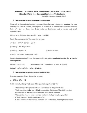
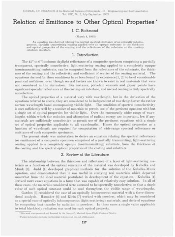
Substi tuting eq (44) in eq (21) we getSD(l - ps) PsR Pe (1- p,) (1- Pe) SD(l - p.) (l - ps) (1- p,Ps)(46)If Pe, Pi, and Ps are zero, as they were under the conditions postulated by Klein [7 J, eq (46 )reduces toSD(47 )R SD 1'which is identical to K lein's eq (48 ).Under the conditions postulated for the derivation of eq (47 ), the emittance will approachzero and the reflectance will approach one as the coating approaches a thickness at which it iscompletely opaque, which will only occur at infinite thickness. Since K O, the absorptanceis zero by definition, and the transmittance is one minus the reflectance. Hence we can wTite1(48)T SD 1'which is identical to Klein's eq (a7).4.2. Example of Computed EmittanceFigure 1 is a plot of emittance, computed from eq (31 ), as a function of thickness for composite specimens with optically smooth surfaces comprised of a coating having an index ofrefraction of 1.40 (from which Pe 0.028, Pi 0.53 ), a value of {3 of 0.8, and values of (]' of 40,20, 13.3, and 10.0 mm- I , respectively, applied over a mat substrate having a reflectance intothe coating of 0.9. (The values of Sand K corresponding to a {3 of 0.8 and (]' of 40, 20, 13.3,and 10 mm- I are as follows: S 8.0, 4 .0, 2.65, and 2.0 nUll- 1 and K 28.44 , 14.22, 9.42, and7.11 111m-I, respectively. ) These conditions might be approximated at wavelengths in thevisible by a glossy gray paint applied over a white backing. All of the coating materials havethe same emissivity (about 0.918 ), but the coating with a (]' value of 40 mm- I r eaches 99 percent of this value at a thickness of 0.05 mm, while the coating with a (]' value or 10 mm- Ir equires a thickness of 0.2 mm to reach the same value.The plotted emittance at zero thickness of the coating is greater than the emittance(0.10 ') of the substrate because the coating has a lower index of refraction than the substrate,and bence reduces reflection at the interface. The plotted value is what would be obtainedwith a very thin, peri'ectly transparent glossy coating having an index of rei';raction of 1.40 .1. Com pu ted normal s pectral emittance ,plotted as a func tion of coating thickn ess, for acom posite s pecimen comprised of partiall y transmitting coatings with opticall y smooth surfaceshaving an index of Tefraction of 1.40, {3 value of0.80, and values of 40, 20, 13.3, and 10 1nm- 1 ,respectively, applied over a substrate haviny areflectance of 0. 90, plotted as a func tion of coatinythickness . T hese conditions would be appToximated by a ylossy yray paint applied ova apolished metal 01' white substrate .FI GU R E(JNote t hat the omittance at zero coating thickness is n ot that ofthe su hstra tc.It was assllmod that even at zero thickn ess, there0. 2would be an eHect 01 the index olrelraction 01the coating. Actually, such eHect would be produced by a trans parent coatin g 010. 1index of refraction of 1.40. 'l"'he coati ng h avi ng a rr val ue of40 rnrn - 1 becomes essentially opaque at abou t 0.05 rnm , an d theother coatin gs at success ive ly greater th icknesses.TH IC KNE SS224OFCO ATI NG. 'n m
4.3. Limitations to EquationsThere are a number of condition encountered in practice t hat deviate from the conditionspostulated in th e derivation of eq (24 ). There will always be a thermal gradient normal tothe surface in any si t ufttio n where a body is heated internally and is dissipftting radiant energy,and the effect of such a gradient h as been omitted in the derivat,ion. In t he case of thick cem miccoatings (typically 0.5 mm or more), significftn t errors may be introduced by ignoring the effectof thermal gradients, especially at high temperatures. The gradients will be negligibly smallwhen the specimen and surroundings are at room temperature or below, and the effect of thegradients in thin coatings, typically less than 0.1 mm, is considered to be negligibly smftll evenat high temperatures .During firing of porcelain enamels and some other types of ceramic coatings, on somem etals, there is appreciable chemical reaction at the coating-metal interface, and some of thereaction products diffuse into the coating for measurable distance. The reaction products maychan ge the reflectance of the substrate into the coatin g, and the reaction products diffusingin to the coating may significantly change its optical properties near the in terface . The extenta nd importance of these effects depend upon the particular materials involved, their thicknesses, the firing , ftnd the service conditions . vVhen the total effect of these factors is large,appropri aLe adjustments in t he values substitu ted into the equation are required for its usefulappli cation. i\10st types of organic and flame-sprayed ceramic coatings, however, will beesse n tially fr ee from these eD'ects.In th e case of some paints, there may be segregation of the pigment particles within Lhevehicle during dryin g, which will also tend to invalidate the equation. For mat coatin gs, wherethe coating-air interface is not optically s mooth even on a micro scale, it may be necessary tom easure Pe and P i experim en tally, instead of computing them from the index of refraction.5 . SummaryThe thermal radiation properties of a composite specimen, comprised of a partially transmitting coatin g applied over an opaque substrate, usually var y significantly with the thicknessof th e coating. An equa tion was derived relating these properties to the thickness of thecoating, the reflectance of the substrate, and the optical properties of the coatin g material.If th e optical proper Lies of a cOttting and t h e l·eilectance of the s ubstrate are known as functionsof wavelength, the equation can be used to compu te (1) the normal spectral emittance (orreflectance) of a ny thickness of coating over the substrate or (2) the thickn ess of t he coatin gover the substrate required to give any normal spectral emittance (or reflectance) within anygiven wavelength interval in termed iate between th e emi ttance of th e substrate and of an in.finitely thick coating.The author gratefully acknowledges the assistance of Louis Joseph, of the Applied Mathematics Division, in checking the mathematics, and of Deane B. Judd, of t he Opticsand Metrology Division, for his advice and helpful suggestions.6. List of SymbolsA absorp tance.T transmittance.R reflectance.E emittance.I diffuse radiant flux proceeding outward from the interior of a specimen.J diffuse radiant flux proceeding inward toward the interior of a specimen.K absorption coefficient.225
-------S backsca ttering coefficient.x distance fro111 the coating-substrate interface to a point in the coating.L a constant that depends upon boundary conditions.u --/K(K 2S).(3 K/ (K 2S).Pe reflectance of the coating-ail' interface for externally-incident diffuse radiant flux.ps reflectance or the substrate for diffuse radiant flux incident on the coating-substrateinterface from within the coating.pi r eflectance oj' the coating-air interface for internally incident diffuse radiant flux .J e externally incident diffuse radiant flux.J o flux J at x O (at coating-substrate interface).I D flux I at x D (at coating-ail' interface).D thickness of coating.M (l (3) - Ps(l - (3).N (l (3) - Pi( l - (3).0 (l - (3 )- Ps(l (3).p (1 - (3) - Pi(l - (3 ).n index or refraction.nl index of refraction in medium from which flux is incident.n 2 index of refraction in medium into which flux is r efracted.'1' angle of incidence, from the normal.8 angle of refraction, from the normal.cp c critical angle of incidence for total internal reflectance.EH hemispherical spectral emittance.PN reflectance of the coating-air interface for normally incident parall el flux.E N normal spectral emittance.R i internal r eflectan ce or a coating. 7. References[1] Judd, D. B. , Optical specification of light -scatte ring matcrials, J. R es. :\lBS 19, 28 7 (1937) H.PIO:26.[2] ASTM Method C 347- 57, R e fl ectiv ity and Coe ffici ent of Scatte r of ViThi te Porcelai n Enamels, ]9 61 ASTMBook of Standard s, pp . 612- 615.[3] Kubelka, P., and F . Munk, Ein Beit rag zu r Optik d er Farbanstriche, Z. t ec h. Ph ys ik, 12, 593 (1931) .[4] Kubelka, P ., New con t ribution s to the optics of intensely light-scattering material s, P ar t 1. J. Opt. Soc.Am . 38, 448 (1948) .[5] Gardon , R , The e miss ivity of t ra nsparen t m aterials, J. Am. Cera m. Soc. 39 [8], 278- 285 (1956) .[6] Hamaker, H. C. , R a diation and heat conduction in light-scatterin g m aterial, Philips R es . Heport:;, 2,55- 67, 103- 111, 112- 125, 420- 425 (1947).[7] Klein , J. D ., H eat transfer by radiation in po\\-ders, Doctor's Disse rtation, Mass. Inst. of T ec hnology (1960) .[8] Wals h, J . W. 1'., The reflection fac tor of a polished glass surface for diffused li ght, D e pt. Sci. and Ind.Res. Illumin ation R esearch, T ech. P aper Ko. 2, p . 10 (1926).[9] Saunderson , J . L ., Calculation of the color of pigmented plastics, J. Opt. Soc . Am . 32 [12], 727- 736.[10] Judd , D. B. , Fresnel reflection of diffu sely incident light, J . R esear ch KBS 29, 329- 332 (1942) RP150.f .(Paper 67C3- 132)226
materials are sufficiently nonselective lo permit use of the pertinent equation with a single set of optical proper Lies applicable Lo all wfLvelengths. Hence the optical properties as fl, function of wavelength are required for computation of wide-range spec