Transcription
PIC32-T795 development boardUSER’S MANUALRevision F, August 2014Designed by OLIMEX Ltd, 2012All boards produced by Olimex LTD are ROHS compliant
OLIMEX 2012PIC32-T795 user's manualDISCLAIMER 2013 Olimex Ltd. Olimex , logo and combinations thereof, are registered trademarks of Olimex Ltd.Other product names may be trademarks of others and the rights belong to their respective owners.The information in this document is provided in connection with Olimex products. No license, expressor implied or otherwise, to any intellectual property right is granted by this document or in connectionwith the sale of Olimex products.This work is licensed under the Creative Commons Attribution-ShareAlike 3.0 Unported License. To view acopy of this license, visit .This hardware design by Olimex LTD is licensed under a Creative Commons Attribution-ShareAlike 3.0Unported License.The software is released under GPL.It is possible that the pictures in this manual differ from the latest revision of the board.The product described in this document is subject to continuous development and improvements. Allparticulars of the product and its use contained in this document are given by OLIMEX in good faith.However all warranties implied or expressed including but not limited to implied warranties ofmerchantability or fitness for purpose are excluded. This document is intended only to assist the reader in theuse of the product. OLIMEX Ltd. shall not be liable for any loss or damage arising from the use of anyinformation in this document or any error or omission in such information or any incorrect use of theproduct.This evaluation board/kit is intended for use for engineering development, demonstration, or evaluationpurposes only and is not considered by OLIMEX to be a finished end-product fit for general consumer use.Persons handling the product must have electronics training and observe good engineering practicestandards. As such, the goods being provided are not intended to be complete in terms of required design-,marketing-, and/or manufacturing-related protective considerations, including product safety andenvironmental measures typically found in end products that incorporate such semiconductor components orcircuit boards.Olimex currently deals with a variety of customers for products, and therefore our arrangement with the useris not exclusive. Olimex assumes no liability for applications assistance, customer product design, softwareperformance, or infringement of patents or services described herein.THERE IS NO WARRANTY FOR THE DESIGN MATERIALS AND THECOMPONENTS USED TO CREATE PIC32-T795. THEY ARE CONSIDEREDSUITABLE ONLY FOR PIC32-T795.Page 2 of 26
OLIMEX 2012PIC32-T795 user's manualTable of ContentsDISCLAIMER. 2CHAPTER 1 OVERVIEW. 51. Introduction to the chapter.51.1 Features.51.2 Organization.5CHAPTER 2 SETTING UP THE PIC32-T795 BOARD.72. Introduction to the chapter.72.1 Electrostatic warning.72.2 Requirements. 72.3 Powering the board.82.4 Prebuilt software.8CHAPTER 3 PIC32-T795 BOARD DESCRIPTION.93. Introduction to the chapter.93.1 Layout (top view).93.2 Layout (bottom view).10CHAPTER 4 THE PIC32MX795F512H MICROCONTROLLER.114. Introduction to the chapter. 114.1 The microcontroller. 11CHAPTER 5 CONTROL CIRCUITY. 135. Introduction to the chapter.135.1 Reset.135.2 Clock. 13CHAPTER 6 HARDWARE.146. Introduction to the chapter.146.1 ICSP connector.146.2 UEXT. 146.3 Pinout of the row headers at the bottom.156.4 USB OTG.166.5 Jumper description.176.6 Additional hardware components. 18CHAPTER 7 MEMORY.197. Introduction to the chapter.197.1 Block diagram of the processor. 197.2 Memory map. 20CHAPTER 8 SCHEMATICS.218. Introduction to the chapter.21Page 3 of 26
OLIMEX 2012PIC32-T795 user's manual8.1 Eagle schematic.218.2 Physical dimensions.23CHAPTER 9 REVISION HISTORY.249. Introduction to the chapter.249.1 Document revision. 249.2 Web page of your device.259.3 Product support. 26Page 4 of 26
OLIMEX 2013PIC32-T795 user's manualCHAPTER 1 OVERVIEW1. Introduction to the chapterThank you for choosing the PIC32-T795 development board from Olimex! This document providesa User’s Guide for the Olimex PIC32-T795 development board. As an overview, this chapter givesthe scope of this document and lists the board’s features. The document’s organization is thendetailed.The PIC32-T795 development board enables code development of applications running on thePIC32MX795F512H microcontroller, manufactured by Microchip.1.1 Features PIC32MX795F512H 80 Mhz microcontroller 512KB Flash 128KB RAM , 3x SPI, 4x I2C,USB OTG, 1MSPS ADC, PMP 80Mhz digital capture, 5 TIMERS/CCP, 53 GPIOsUSB-OTG supporting both Host and Device functions and allows the implementation ofGoogle Android ADKComes programmed with Duinomite bootloader – even if you lack programmer tool you canprogram the board using the mini USBUEXT connector which allows many existing modules like RF, ZIGBEE, GSM, GPS to beconnectedtwo LEDsone BUTTONsRESET buttonmini USB connector is used which is common and used in most cell phones, so you do nothave to buy other cablesall PIC ports available on 0.1" connectorsICSP connector allows programming with PIC-KIT3Dimensions 87 54 mm (3.4 2.12")1.2 OrganizationEach section in this document covers a separate topic, organized as follow:– Chapter 1 is an overview of the board usage and features– Chapter 2 provides a guide for quickly setting up the board– Chapter 3 contains the general board diagram and layout– Chapter 4 describes the component that is the heart of the board: the PIC32MX795F512Hmicrocontroller– Chapter 5 is an explanation of the control circuitry associated with the microcontroller toreset. Also shows the clocks on the boardPage 5 of 26
OLIMEX 2013––––PIC32-T795 user's manualChapter 6 covers the connector pinout, peripherals and jumper descriptionChapter 7 shows the memory mapChapter 8 provides the schematicsChapter 9 contains the revision historyPage 6 of 26
OLIMEX 2013PIC32-T795 user's manualCHAPTER 2 SETTING UP THE PIC32-T795 BOARD2. Introduction to the chapterThis section helps you set up the PIC32-T795 development board for the first time.Please consider first the electrostatic warning to avoid damaging the board, then discover thehardware and software required to operate the board.The procedure to power up the board is given, and a description of the default board behavior isdetailed.2.1 Electrostatic warningPIC32-T795 is shipped in a protective anti-static package. The board must not be exposed to highelectrostatic potentials. A grounding strap or similar protective device should be worn whenhandling the board. Avoid touching the component pins or any other metallic element.2.2 RequirementsIn order to set up the PIC32-T795, the following items are required:- miniUSB to USB A cable- Computer work stationHighly recommended items:- Breadboard ino/Breadboarding/BREADBOARD-MINI/- PIC32 compatible programmer/debugger. You can use our PIC-KIT3 forprogramming/debugging C-KIT3/- Jumper wires for boarding/BREADBOARD-MINI/The breadboard helps you use the free pins at the bottom of the board with jumper wires withoutsoldering. Also makes applying external supply easier.Additionally a host-based software toolchain is required in order to program/debug the PIC32-T795board.Page 7 of 26
OLIMEX 2013PIC32-T795 user's manual2.3 Powering the boardThe board is powered either by the mini USB or by the SUPPLY1 or SUPPLY2 line(when the boardis mounted on the breadboard you might use the VCC and the VDD breadboard bus).On powering the board PWR and LED2 LEDS turn on.The board comes with preloaded Duinomite bootloader. For more information on Duinomite checkthe following links and mex.com/Products/Duino/Duinomite/DUINOMITE-MEGA/If you don't remove the bootlader the board comes with, when connected via the USB OTG thedevice should be recognized as a COMx. If it doesn't get recognized this means you lack the driverfor your operating system.2.4 Prebuilt softwareOn arrival the board has a Duinomite bootloader installed.Connect the board to the computer work station (e.g. PC) via the USB OTG. Open the devicemanager and check which COM port the device initialized at. Launch your favorite terminalprogram at the COM port found at 115200 baud. Press “Enter” on your keyboard. Write “setup”command in the terminal.For more comprehensive set of example and notes on the MM-Basic check the user manuals of theDuinomite boards.The board can be relatively easy configured for use with Piunguino IDE also. You would need tochange the SMT jumper at the bottom of the board from RD8 (default) position to RD0. This isrequired since Pinguino and Duinomite bootloaders use different pins for the button required toenter bootloader mode. All files that might be required to change to Pinguino IDE are available atthe PIC32-T795H's website.Page 8 of 26
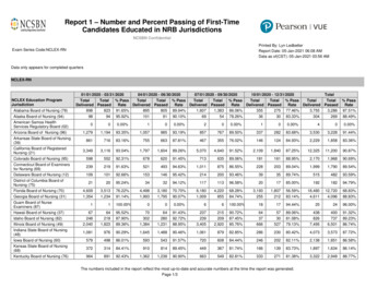
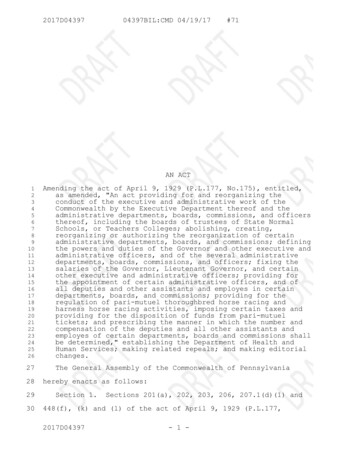
OLIMEX 2013PIC32-T795 user's manualCHAPTER 3 PIC32-T795 BOARD DESCRIPTION3. Introduction to the chapterHere you get acquainted with the main parts of the board. Note the names used on the board differfrom the names used to describe them. For the actual names check the PIC32-T795 board itself.3.1 Layout (top view)The T-shape design is based on idea by Ken Segler (www.KENSEGLERDESIGNS.com).Page 9 of 26
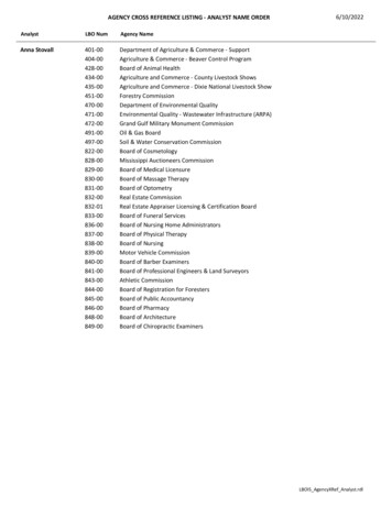
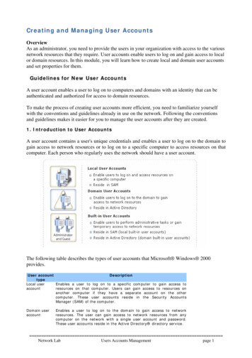
OLIMEX 2013PIC32-T795 user's manual3.2 Layout (bottom view)Page 10 of 26
OLIMEX 2013PIC32-T795 user's manualCHAPTER 4 THE PIC32MX795F512H MICROCONTROLLER4. Introduction to the chapterIn this chapter is located the information about the heart of PIC32-T795 – its microcontroller. Theinformation is a modified version of the datasheet provided by its manufacturers.4.1 The microcontrollerPIC32-T795 board uses PIC32MX795F512H from Microchip Technology with these features:High-Performance 32-bit RISC CPU: MIPS32 M4K 32-bit core with 5-stage pipeline 80 MHz maximum frequency 1.56 DMIPS/MHz (Dhrystone 2.1) performance at zero Wait state Flash access Single-cycle multiply and high-performance divide unit MIPS16e mode for up to 40% smaller code size Two sets of 32 core register files (32-bit) to reduce interrupt latency Prefetch Cache module to speed execution from FlashMicrocontroller Features: Operating voltage range of 2.3V to 3.6V 512K Flash memory (plus an additional 12 KB of Boot Flash) 128K SRAM memory Pin-compatible with most PIC24/dsPIC DSC devices Multiple power management modes Multiple interrupt vectors with individually programmable priority Fail-Safe Clock Monitor mode Configurable Watchdog Timer with on-chip Low-Power RC oscillator for reliable operationPeripheral Features: Atomic SET, CLEAR and INVERT operation on select peripheral registers 8-channels of hardware DMA with automatic data size detection USB 2.0-compliant full-speed device and On-The-Go (OTG) controller: Dedicated DMA channels 10/100 Mbps Ethernet MAC with MII and RMII interface: Dedicated DMA channels CAN module: 2.0B Active with DeviceNet addressing support Dedicated DMA channelsPage 11 of 26
OLIMEX 2013PIC32-T795 user's manual 3 MHz to 25 MHz crystal oscillator Internal 8 MHz and 32 kHz oscillators Six UART modules with: RS-232, RS-485 and LIN 1.2 support IrDA with on-chip hardware encoder and decoder Four SPI modules Five I2C modules Separate PLLs for CPU and USB clocks Parallel Master and Slave Port (PMP/PSP) with 8-bit and 16-bit data, and up to 16 addresslines Hardware Real-Time Clock and Calendar (RTCC) Five 16-bit Timers/Counters (two 16-bit pairs combine to create two 32-bit timers) Five Capture inputs Five Compare/PWM outputs Five external interrupt pins High-speed I/O pins capable of toggling at up to 80 MHz High-current sink/source (18 mA/18 mA) on all I/O pins Configurable open-drain output on digital I/O pinsDebug Features: Two programming and debugging Interfaces: 2-wire interface with unintrusive access and real-time data exchange with application 4-wire MIPS standard enhanced Joint Test Action Group (JTAG) interface Unintrusive hardware-based instruction trace IEEE Standard 1149.2 compatible (JTAG) boundary scanAnalogue Features: 16-channel, 10-bit Analog-to-Digital Converter: 1 Msps conversion rate Conversion available during Sleep and Idle Two Analog Comparators 5V tolerant input pins (digital pins only)Page 12 of 26
OLIMEX 2013PIC32-T795 user's manualCHAPTER 5 CONTROL CIRCUITY5. Introduction to the chapterHere you can find information about reset circuit and quartz crystal locations.5.1 ResetPIC32-T795 reset circuit includes R13 (4.7 kΩ), R14 (330 Ω), R66(560 Ω), C21(100 nF), D3(1N4148), PIC32MX795F512H pin 7 (#MCLR) and a RESET button. The RESET is alsoconnected to the ICSP pin 1.5.2 Clock8 MHz quartz crystal Q1 is connected to pins 39 and 40 of the processor.Real time clock (RTC) Q2 is found at pins 47 and 48 of the processor.IMPORTANT: If the board has a quartz crystal rotated at 45 degrees relative to the pads provideddo not panic. This is normal. We have two types of such crystals – one of them requires 4 pads, theother only 2 pads. That is why we have provided 4 pads to be able to fit both crystals. All boardsOlimex manufactures pass automatized optical inspection after assembly and obviousmisplacements like these are impossible to occur.Page 13 of 26
OLIMEX 2013PIC32-T795 user's manualCHAPTER 6 HARDWARE6. Introduction to the chapterIn this chapter are presented the connectors that can be found on the board all together with theirpinout. Jumpers functions are described. Notes and info on specific peripherals are presented. Notesregarding the interfaces are given.6.1 ICSP connectorNote that the ICSP connector mounted on the board is the one with the larger step – 100 mil.ICSP connectorPin #Signal NamePin #Signal Name1RESET4PGED12 3.35PGEC13GND6Not connected6.2 UEXTPIC32-T795 board has UEXT connector and can interface Olimex's UEXT modules.For more information on UEXT please Pin #Signal Name1 3.3V2GND3U2TX4U2RX5SCL16SDA1Page 14 of 26
OLIMEX 20137MISO8MOSI9SCK10#CSPIC32-T795 user's manual6.3 Pinout of the row headers at the bottomFor your convenience the pads are named individually near each of them. Please take extra careabout the numbering but consider that there might be offset.PIN# MCU Pin # – Port Name (Used for)PIN# MCU Pin # - Port Name (Used for)113 – RB32546 – RD0 (PINGUINO BOOT)212 – RB42652 – RD4317 – RB62753 – RD5418 – RB72854 – RD6522 – RB92955 – RD7623 – RB103058 – RF0745 – RD113159 – RF1851 – RD3 (MOSI)3232 – RF5 (U2TX)950 – RD2 (UEXT)3331 – RF4 (U2RX)1049 – RD1 (SCK)3421 – RB81160 – RE03529 – RB141261 – RE13628 – RB131362 – RE23730 – RB15 (LED1)1463 – RE3384 – RG61564 – RE4395 – RG7 (USB FAULT)161 – RE5406 – RG8172 – RE6418 – RG9183 – RE74211 – RB5 (VBUSON)1924 – RB11 (#CS)4314 – RB2Page 15 of 26
OLIMEX 2013PIC32-T795 user's manual2027 – RB12 (LED2)4415 – RB1 (PGEC1)2133 – RF3 (USB ID)4516 – RB0 (PGED1)2242 – RD8 (DUINOMITE BOOT)3.3V 3.3V2343 – RD9 (SDA1)GND2444 – RD10 (SCL1) 5V 5VEXTGND6.4 USB OTGUSB-OTG can act makes possible to USB devices to the board. It makes the board act either asUSB device or USB host.Pin #Signal Name1VBUS2D-3D 4USB ID5GNDPage 16 of 26
OLIMEX 2013PIC32-T795 user's manual6.5 Jumper descriptionMost of the jumper configurations are printed with white print on the PCB for your convenience.Note that all of the jumpers on the board are SMD type. You will need basic soldering skills to beable to close those jumpers. If you have to separate already connected ones unsolder them and ifneeded cut the wire between the pads with cutter knife.5V E (optional)In first few revisions of the board this jumper (when closed) was meant to enable 5V to theSUPPLY1 and SUPPLY2 lines (by default 3.3V) when closed but it also raised the processor'svoltage way beyond the acceptable levels so the jumper was removed in latest revisions.Please do not close 5V E or you might damage the microcontroller on your PIC32-T795.Default state is open.RD8/RD0Changes the default boot pin. If RD8 is selected starts with Duinomite bootloader. If RD0 isselected Pinguino bootloader.The difference between the two bootloaders is the processor pin used for the button. Duinomitebootloader may be found at the Duinomite repository and Pinguino bootloader may be found in thePinguino IDE folders.Default positions is RD8.EE SCL1 E & EE SDA1 EThese jumpers must be moved together. When open disconnect the EEPROM. If you use UEXTconnector for something different than I2C better cut both these jumpers.Default state is closed.Page 17 of 26
OLIMEX 2013PIC32-T795 user's manual6.6 Additional hardware componentsThe components below are mounted on PIC32-T795 but are not discussed above. They are listedhere for completeness:user button RST button2 user LEDs PWR LEDPage 18 of 26
OLIMEX 2013PIC32-T795 user's manualCHAPTER 7 MEMORY7. Introduction to the chapterOn the next page you can find a memory map for this family of processors. It is stronglyrecommended to refer to the original datasheet released by Microchip for one of a higher quality.7.1 Block diagram of the processorPage 19 of 26
OLIMEX 2013PIC32-T795 user's manual7.2 Memory mapPage 20 of 26
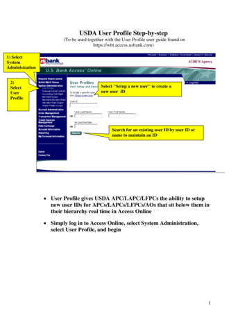
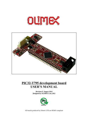
OLIMEX 2013PIC32-T795 user's manualCHAPTER 8 SCHEMATICS8. Introduction to the chapterIn this chapter are located the schematics describing logically and physically PIC32-T795.8.1 Eagle schematicPIC32-T795 schematic is visible for reference here. You can also find them on the web page forPIC32-T795 at our site: T795/. They arelocated in HARDWARE section.The EAGLE schematic is situated on the next page for quicker reference.Page 21 of 26
OLIMEX 2012PIC32-T795 User's ManualUSB-OTG 5V 5V EXTICSPU13.3V AVCC3.3V7RESET1.8V CORE 5610uF/6.3V10k10k5738261019R1R2C1C2C3100nF100nF 100nFC4C5100nF2092541USB FAULTC7 27pFU27123IN#EN#FLGGNDMIC2075YMT1Q1C8 27pFC10 27pFQ8.000MHz/20pFC9 27pF10 k47 kGND2GND1VBUSDD USB IDUSBGND4GND33.3VDTC114YKAVBUSDD IDGND60616263641231112131415161718Q2GN DQCT 100nF865435343637VBUSDD C15 N0/VREF /CVREF N-/CN4/RB2AN3/C2IN /CN5/RB3AN4/C1IN-/CN6/RB4AN5/C1IN LL/PMA0/CN12/RB15C6100nF4568USB O/T1CK/CN0/RC14SOSCI/CN1/RC13VUSBVBUSD-/RG3D CN18/RF5USB IDU2RXU2TX3.3V45444312423434561920363537VBUSON46 PINGUINO BOOT49SCK50MISO51MOSI5253545542 DUINOMITE 17182122232427282930#MCLRVCAP/VCOREVDDVDDVDDVDD Pins are up to 5V 1MISOSCK30312133323.3V 2MX795F512H-80I/PT3.3VPIC32-T795H Rev.BDesigned by: WWW .OLIMEX.COM/DEVBASED ON WW W.KENSEGLERDESIGNS.COM IDEAReleased under Creative Commons Attribution-Share Alike 3.0 United States LicensePOWER SUPPLYC1610nF3.3V3.3VR9100k/1%STAT LEDS3.3VR120R0R(NA)R14330RDUINOMITE BOOTclose67321SCLWPA2A1A0LED224LC256-I/SNPage 22 of CEEPROMArrayC22100nFR16330REE SCL1 E2SCL1 ESETRSTR18NA(4.7k)PINGUINO BOOTD31N4148/mini-mel 0R/1%GND3.3VOUTC191N5819S/SS14 5V DJHN1x2 5VD2HN1x2D1 5V EXTSUPPLY1 SUPPLY23.3V3.3V2openRD8/RD05V E1PWRVBUSLED0603/RED 5V1N5819S/SS14LED15EE SDA1 E12 SDA1close
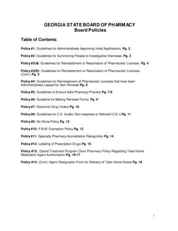
OLIMEX 2013PIC32-T795 user's manual8.2 Physical dimensionsNote that all dimensions are in inches.Page 23 of 26
OLIMEX 2013PIC32-T795 user's manualCHAPTER 9 REVISION HISTORY9. Introduction to the chapterIn this chapter you will find the current and the previous version of the document you are reading.Also the web-page for your device is listed. Be sure to check it after a purchase for the latestavailable updates and examples.9.1 Document revisionRevisionAChangesInitial CreationModifiedPagesAllImproved the document formattingFixed error about RD8/RD0 jumperBAdded info on how to switch between Pinguinoand Duinomite modeAllAdded links to the indexUpdated linksFixed an error about pin #8 on page 15CAllUpdated linksUpdated the disclaimerD17Added a warning about the 5V E jumperFixed wrong bottom view picture10Added more info about Pinguino boot mode8Added a note about rotated quartz crystal13EFPage 24 of 26
OLIMEX 2013PIC32-T795 user's manual9.2 Web page of your deviceThe web page you can visit for more info on your device 2-T795/. There you can find more info andsome examples.ORDER CODES:PIC32-T795 – completely assembled and testedUSB-MINI-CABLE – USBmini to USB-A cablePIC-KIT3 – for custom programming/debuggingHow to order?You can order directly using our web shop or via any of our distributors. The list of distributors isavailable here: https://www.olimex.com/Distributors/.Check our webpage https://www.olimex.com/ for more info.Page 25 of 26
OLIMEX 2013PIC32-T795 user's manual9.3 Product supportFor product support, hardware information and error reports mail to: support@olimex.com. Notethat we are primarily a hardware company and our software support is limited.Please consider reading the paragraph below about the warranty of Olimex products.Warranty and returns:Our boards have lifetime warranty against manufacturing defects andcomponents.During development work it is not unlikely that you can burn your programmeror development board. This is normal, we also do development work and we havedamaged A LOT of programmers and boards during our daily job so we know how itworks. If our board/programmer has worked fine then stopped, please check ifyou didn't apply over voltage by mistake, or shorted something in your targetboard where the programmer was connected etc. Sometimes boards might getdamaged by ESD shock voltage or if you spill coffee on them during your workwhen they are powered.Please note that warranty do not cover problems caused by improper use,shorts, over-voltages, ESD shock etc.If the board has warranty label it should be not broken. Broken labels voidthe warranty, same applies for boards modified by the customer, for instancesoldering additional components or removing components – such boards will benot be a subject of our warranty.If you are positive that the problem is due to manufacturing defect orcomponent you can return the board back to us for inspection.When we receive the board we will check and if the problem is caused due toour fault and we will repair/replace the faulty hardware free of charge,otherwise we can quote price of the repair.Note that all shipping costs back and forth have to be covered by thecustomer. Before you ship anything back you need to ask for RMA. When you shipback please attach to it your shipping address, phone, e-mail, RMA# and briefdescription of the problem. All boards should be sent back in antistaticpackage and well packed to prevent damages during the transport.Page 26 of 26
This evaluation board/kit is intended for use for engineering development, demonstration, or evaluation . Google Android ADK Comes programmed with Duinomite bootloader - even if you lack programmer tool you can . This section helps you set up the PIC32-T795 development board for the first time.