Transcription
IEEE Green Book : IEEE STD 142-2007Recommended Practice for Grounding ofIndustrial and Commercial Power Systems
Recognized as an American National Standard (ANSI)IEEE Std 142-1991(Revision of IEEE Std 142-1982)IEEE Recommended Practice forGrounding of Industrial and CommercialPower SystemsSponsorPower Systems Engineering Committeeof theIEEE Industry Applications SocietyApproved June 27, 1991IEEE Standards BoardApproved December 9, 1991American National Standards InstituteAbstract: The problems of system grounding, that is, connection to ground of neutral, of the corner of thedelta, or of the midtap of one phase, are covered. The advantages and disadvantages of grounded versusungrounded systems are discussed. Information is given on how to ground the system, where the systemshould be grounded, and how to select equipment for the grounding of the neutral circuits. Connecting theframes and enclosures of electric apparatus, such as motors, switchgear, transformers, buses, cablesconduits, building frames, and portable equipment, to a ground system is addressed. The fundamentals ofmaking the interconnection or ground-conductor system between electric equipment and the ground rods,water pipes, etc. are outlined. The problems of static electricity—how it is generated, what processes mayproduce it, how it is measured, and what should be done to prevent its generation or to drain the staticcharges to earth to prevent sparking—are treated. Methods of protecting structures against the effects oflightning are also covered. Obtaining a low-resistance connection to the earth, use of ground rods,connections to water pipes, etc. is discussed. A separate chapter on sensitive electronic equipment isincluded.Keywords: System grounding, equipment grounding, static and lightning protection grounding, connectionto earth, and sensitive electronic equipment grounding.
Corrected EditionThird PrintingApril 1996This edition incorporates corrections to minor typographical errors. In several cases, typographical errors in theoriginal text could lead to misinterpretation. Changes of this type are indicated in the text by a change bar running inthe left margin next to the corrected line in the text. This occurs on pages 25, 26, 31, 85, 137, 176, 180, and 181.The Institute of Electrical and Electronics Engineers, Inc.345 East 47th Street, New York NY 10017-2394, USACopyright 1992 by theInstitute of Electrical and Electronics Engineers, Inc.All rights reserved. Published 1992Printed in the United States of AmericaISBN 1-55937-141-2Library of Congress Catalog Card Number 92-81909No part of this publication may be reproduced in any form, in an electronic retrieval system or otherwise, without theprior written permission of the publisher.June 22, 1992SH14498ii
IEEE Standards documents are developed within the Technical Committees of the IEEE Societies and the StandardsCoordinating Committees of the IEEE Standards Board. Members of the committees serve voluntarily and withoutcompensation. They are not necessarily members of the Institute. The standards developed within IEEE represent aconsensus of the broad expertise on the subject within the Institute as well as those activities outside of IEEE whichhave expressed an interest in participating in the development of the standard.Use of an IEEE Standard is wholly voluntary. The existence of an IEEE Standard does not imply that there are no otherways to produce, test, measure, purchase, market, or provide other goods and services related to the scope of the IEEEStandard. Furthermore, the viewpoint expressed at the time a standard is approved and issued is subject to changebrought about through developments in the state of the art and comments received from users of the standard. EveryIEEE Standard is subjected to review at least every five years for revision or reaffirmation. When a document is morethan five years old, and has not been reaffirmed, it is reasonable to conclude that its contents, although still of somevalue, do not wholly reflect the present state of the art. Users are cautioned to check to determine that they have thelatest edition of any IEEE Standard.Comments for revision of IEEE Standards are welcome from any interested party, regardless of membership affiliationwith IEEE. Suggestions for changes in documents should be in the form of a proposed change of text, together withappropriate supporting comments.Interpretations: Occasionally questions may arise regarding the meaning of portions of standards as they relate tospecific applications. When the need for interpretations is brought to the attention of IEEE, the Institute will initiateaction to prepare appropriate responses. Since IEEE Standards represent a consensus of all concerned interests, it isimportant to ensure that any interpretation has also received the concurrence of a balance of interests. For this reasonIEEE and the members of its technical committees are not able to provide an instant response to interpretation requestsexcept in those cases where the matter has previously received formal consideration.Comments on standards and requests for interpretations should be addressed to:Secretary, IEEE Standards Board445 Hoes LaneP.O. Box 1331Piscataway, NJ 08555-1331USAIEEE Standards documents are adopted by the Institute of Electrical and Electronics Engineers without regard towhether their adoption may involve patents on articles, materials, or processes. Such adoption does not assumeany liability to any patent owner, nor does it assume any obligation whatever to parties adopting the standardsdocuments.iii
Foreword(This Foreword is not a part of IEEE Std 142-1991, IEEE Recommended Practice for Grounding of Industrial and CommercialPower Systems.)This book is a revision of IEEE Std 142-1982. This recommended practice has served electrical engineers seekingelectrical system grounding information since the first edition in 1956. It reflects the experience and sound judgmentof a working group made up of engineers active in the design and operation of electrical systems for industrial andcommercial power systems.The working group owes a debt of gratitude to the authors of previous editions. The members of the working group forthe original 1956 edition were: D. L. Beeman (Chairman), D. M. Allison, H. H. Angel, J. E. Arberry, K. M. Bausch,A. J. Bisson, L. J. Carpenter, M. A. Leland, F. R. Longley, C. C. Saunders, J. M. Schmidt, H. E. Springer, H. M.Stewart, T. O. Sweatt, H. B. Thacker, and B. F. Thomas, Jr. Others who worked on the interim editions that were noton the present working group are: Thad Brown, W. H. Cook, L. S. Corey, J. W. Couter, D. C. Grant, C. A. Hatstat, T.L. Haymes, C. F. Hedlund, R. H. Kaufmann, R. Loewe, B. K. Mathur, E. S. Raila, and F. J. Shields.We consider this a major revision of the text. Much new material has become available since the 1982 edition. Chapter 1,System Grounding, has been expanded and revised throughout. Chapter 2, Equipment Grounding, has been carefullyreviewed and revised in the light of experience. Chapter 3, Static and Lightning Protection Grounding, has importantnew material on grounding of high-rise structures. Chapter 4, Connection to Earth, required the fewest changes but hasimportant updating, such as the caution in using stainless steel ground rods. Chapter 5, Sensitive Electronic EquipmentGrounding, is completely new. It includes methods of grounding that include noise control and are consistent with theNational Electrical Code.This has been a project of the Power Systems Grounding Subcommittee of the Power Systems EngineeringCommittee. Members of the subcommittee and working group during this period were:Gordon S. Johnson, ChairKenneth E. AlmonBaldwin BridgerNewton S. BurleyEdward CantwellRalph H. Lee (deceased)Richard E. LoydRobert G. MedleyDaleep C. MohlaRichard L. NailenWilliam J. NeiswenderNeil NicholsDev PaulElliot RappaportMilt RobinsonLynn F. SaundersRobert L. SimpsonMark G. TheriaultS. I. VenugopalanDonald W. ZipseThe working group received invaluable comments and text material from coordinating groups in the Power SystemsProtection Committee, the Computer Society, the Power Engineering Society, the National Electrical ManufacturersAssociation, Underwriters Laboratories, the International Electrotechnical Commission, and others. A partial list ofother contributors and reviewers includes:Carrol BurtnerWalter V. ChumakovNorman H. Davis, IIIRobert DempseyPaul DuksThomas GruzivChes HeathJohn HolladayDavid JacksonRichard P. KeilCharles A. LennonDaniel LoveS. R. MendisLloyd A. MorleyJames ProtheroJames Skiles
The following persons were on the balloting committee that approved this document for submission to the IEEEStandards Board:Kenneth E. AlmonBaldwin BridgerNewton S. BurleyEdward CantwellGordon S. JohnsonRobert G. MedleyDaleep C. MohlaRichard L. NailenWilliam J. NeiswenderNeil NicholsDev PaulElliot RappaportMilt RobinsonLynn F. SaundersRobert L. SimpsonMark G. TheriaultS. I. VenugopalanDonald W. ZipseWhen the IEEE Standards Board approved this standard on June 27, 1991, it had the following membership:Marco W. Migliaro, ChairDonald C. Loughry, Vice ChairAndrew G. Salem, SecretaryDennis BodsonPaul L. BorrillClyde CampJames M. DalyDonald C. FleckensteinJay Forster *David F. FranklinIngrid FrommThomas L. HannanDonald N. HeirmanKenneth D. HendrixJohn W. HorchBen C. JohnsonIvor N. KnightJoseph Koepfinger*Irving KolodnyMichael A. LawlerJohn E. May, Jr.Lawrence V. McCallT. Don Michael*Stig L. NilssonJohn L. RankineRonald H. ReimerGary S. RobinsonTerrance R. Whittemore*Member EmeritusAlso included are the following nonvoting IEEE Standards Board liaisons:Fernando AldanaSatish K. AggarwalJames BeallRichard B. EngelmanStanley WarshawPeter ArnoldIEEE Standards Project Editorv
IEEE Recommended Practice forGrounding of Industrial and CommercialPower Systems5th EditionWorking Group Members and ContributorsGordon Johnson, Working Group ChairChapter 1—System Grounding:Neil Nichols, ChairChapter 2—Equipment Grounding:Elliot Rappaport, ChairChapter 3—Static and Lightning Protection Grounding:Baldwin Bridger, ChairChapter 4—Connection to Earth:Kenneth B. Almon, ChairChapter 5—Sensitive Electronic Equipment Grounding:Donald W. Zipse and Ralph H. Lee, Cochairsvi
CLAUSEPAGEChapter 1 System Grounding .11.1 Introduction . 11.2 Definitions. 21.3 Purposes of System Grounding. 31.4 Methods of System Neutral Grounding . 41.5 Grounding at Points Other than System Neutral. 101.6 Location of System Grounding Points . 131.7 [Reserved for Future Use]. 211.8 Grounding of Industrial Generators . 211.9 System Grounding for Uninterruptible Power Systems. 241.10 Multi-Voltage Systems . 321.11 Portable Mining Equipment Supply Systems . 461.12 References . 491.13 Bibliography. 51Chapter 2 Equipment Grounding .522.1 Basic Objectives. 522.2 Fundamental Concepts . 552.3 Equipment Grounding as Influenced by Type of Use. 662.4 Outdoor Open Frame Substations . 672.5 Outdoor Unit Substations. 722.6 Installations Serving Heavy Portable Electric Machinery . 742.7 Interior Wiring Systems . 782.8 Interior Unit Substations and Switching Centers. 822.9 Utilization Equipment . 872.10 References . 902.11 Bibliography. 91Chapter 3 Static and Lightning Protection Grounding.933.1 Introduction . 933.2 Static Grounding . 933.3 Lightning Protection Grounding . 1103.4 References . 1233.5 Bibliography. 125Chapter 4 Connection to Earth.1264.1 Resistance to Earth. 1264.2 Ground Electrodes. 1334.3 Methods and Techniques of Construction . 1364.4 Measurement of Resistance to Earth. 1384.5 References . 142vii
CLAUSEPAGEChapter 5 Sensitive Electronic Equipment Grounding .1455.1 Introduction . 1455.2 Definitions. 1455.3 History of Computer Grounding . 1465.4 System or Equipment to Be Grounded . 1485.5 Computer Grounds. 1495.6 Effects of Internal Rectifiers in Computers . 1575.7 Grounding of Shields . 1585.8 Interference from Radio Frequencies. 1615.9 Case Histories . 1615.10 References . 1635.11 Bibliography. 164viii
IEEE Recommended Practice forGrounding of Industrial and CommercialPower SystemsChapter 1System Grounding1.1 IntroductionGrounding of an electrical system is a decision that must be faced sometime by most engineers charged with planningor modifying electrical distribution. Grounding in some form is generally recommended, although there are certainexceptions. Several methods and criteria exist for system grounding; each has its own purpose.It is the intention of this section to assist the engineer in making decisions on the subject by presenting basic reasonsfor grounding or not grounding and by reviewing general practices and methods of system grounding.The practices set forth herein are primarily applicable to industrial power systems that distribute and utilize power atmedium or low voltage, usually within a smaller geographical area than is covered by a utility.Where distances or power levels may dictate circuitry and equipment similar to a utility, consideration of utilitypractices is warranted. However, restrictions of the National Electrical Code (NEC) (ANSI/NFPA 70–1990) [1],1particular needs of service, and the experience and training of the workforce should also be considered.Where an industrial power system includes power-generating equipment, the reasons for grounding these componentsmay be the same as those for grounding similar components of public utility systems. The methods of groundingwould generally be similar under like conditions of service. However, in the industrial setting, conditions of servicemay be altered by:1)2)3)Location within the power systemIndividual generator characteristicsManufacturing process requirements1The numbers in brackets correspond to those of the references in 1.12.Copyright 1992 IEEE All Rights Reserved1
IEEE Std 142-1991IEEE RECOMMENDED PRACTICE FOR GROUNDING OFAll of these may affect grounding decisions.The NEC [1], sponsored by the National Fire Protection Association, contains regulations pertaining to system andequipment grounding applicable to industrial, commercial, and special occupancy facilities. These rules areconsidered minimum requirements for the protection of life and property and should be carefully reviewed during thecourse of system design.1.2 DefinitionsThe varieties of system grounding and definitions of related terminology follow. The definitions of additional termsmay be found in IEEE Std 100-1988 [2] and the NEC [1].effectively grounded: Grounded through a sufficiently low impedance such that for all system conditions the ratio ofzero-sequence reactance to positive-sequence reactance (X0/X1) is positive and less than 3, and the ratio of zerosequence resistance to positive-sequence reactance (R0/X1) is positive and less than 1.grounded system: A system in which at least one conductor or point (usually the middle wire or neutral point oftransformer or generator windings) is intentionally grounded, either solidly or through an impedance.grounded: Connected to earth or to some extended conducting body that serves instead of the earth, whether theconnection is intentional or accidental.high resistance grounded: A grounded system with a purposely inserted resistance that limits ground-fault currentsuch that the current can flow for an extended period without exacerbating damage. This level of current is commonlythought to be 10 A or less. High-resistance grounded systems are designed to meet the criterion of RO XCO to limit thetransient overvoltages due to arcing ground faults. XCO is the distributed per-phase capacitive reactance to ground ofthe system, and RO is the per-phase zero-sequence resistance of the system.low resistance grounded: A resistance-grounded system in which the purposely inserted resistance has lower ohmicvalue than would meet the high-resistance grounding criteria. The resistance is selected to provide the desired relayingcurrent.per-phase charging current: (ICO). The current (VLN/XCO) that passes through one phase of the system to charge thedistributed capacitance per phase to ground of the system, VL-N is the line-to-neutral voltage and XCO is the per-phasedistributed capacitive reactance of the system.R0: The per-phase zero-sequence resistance of the system.reactance grounded: Grounded through impedance, the principal element of which is inductive reactance.resistance grounded: Grounded through an impedance, the principal element of which is resistance.resonance: The enhancement of the response of a physical system (electrical system or circuit) to a periodic excitationwhen the excitation frequency (f) is equal to a natural frequency of the system. In a series circuit consisting ofresistance (R), inductance (L), and capacitance (C), when L and C parameters are such that the resultant reactancebecomes zero and the current reaches maximum, then the circuit is in series resonance. This happens when11ωL -------- or f -----------------ωC2π LCSimilarly, in a parallel circuit consisting of R, L, and C, the admittance is the lowest when 1/X1 1/Xc, and the circuitis in parallel resonance. This happens when11ωL -------- or f -----------------ωC2π LCRn: The value of the resistance connected from the neutral to the ground of a resistance-grounded system. For highresistance grounded systems where RN is a major component of Ro, the relationship R0 3RN applies.2Copyright 1992 IEEE All Rights Reserved
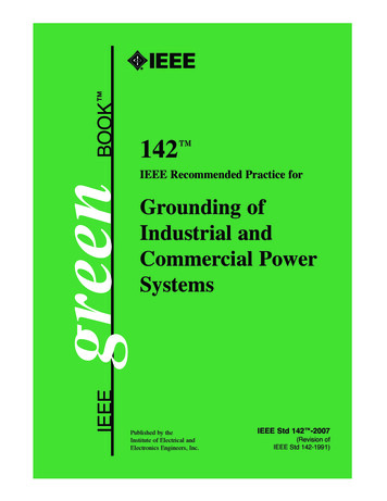
INDUSTRIAL AND COMMERCIAL POWER SYSTEMSIEEE Std 142-1991solidly grounded: Connected directly through an adequate ground connection in which no impedance has beenintentionally inserted.static charge: The electricity generated when two dissimilar substances come into contact. Conveyor belts are activeproducers of static electricity.switching surge: A transient wave of overvoltage in an electric circuit caused by the operation of a switching deviceinterrupting load current or fault current.system: A grounding system consists of all interconnected grounding connections in a specific power system and isdefined by its isolation from adjacent; grounding systems. The isolation is provided by transformer primary andsecondary windings that are coupled only by magnetic means. Thus, the system boundary is defined by the lack of aphysical connection that is either metallic or through a significantly high impedance. Fig 1 illustrates the limits andboundaries of grounding systems.system charging current: The total distributed capacitive charging current (3VLN/XCO) of a three-phase system.three-phase four-wire system: A system of alternating current supply comprising four conductors, three of which areconnected as in a three-phase three-wire system, the fourth being connected to the neutral point of the supply ormidpoint of one-phase in case of delta-connected transformer secondary, which may be grounded.three-phase three-wire system: A system of alternating current supply comprising three conductors, betweensuccessive pairs of which are maintained alternating differences of potential successively displaced in phase by onethird of a period.transient overvoltage: The temporary overvoltage of short duration associated with the operation of the switchingdevice, a fault, a lightning stroke, or during arcing ground faults on the ungrounded system.ungrounded system: A system, without an intentional connection to ground, except through potential indicating ormeasuring devices or other very high impedance devices.1.3 Purposes of System GroundingSystem grounding, or the intentional connection of a phase or neutral conductor to earth, is for the purpose ofcontrolling the voltage to earth, or ground, within predictable limits. It also provides for a flow of current that willallow detection of an unwanted connection between system conductors and ground and which may instigate operationof automatic devices to remove the source of voltage from conductors with such undesired connections to ground. TheNEC [1], prescribes certain system grounding connections that must be made to be in compliance with the code. Thecontrol of voltage to ground limits the voltage stress on the insulation of conductors so that insulation performance canmore readily be predicted. The control of voltage also allows reduction of shock hazard to persons who might come incontact with live conductors.Copyright 1992 IEEE All Rights Reserved3
IEEE Std 142-1991IEEE RECOMMENDED PRACTICE FOR GROUNDING OFFigure 1—Grounding Systems1.4 Methods of System Neutral Grounding1.4.1 IntroductionMost grounded systems employ some method of grounding the system neutral at one or more points. These methodscan be divided into two general categories: Solid grounding and impedance grounding. Impedance grounding may befurther divided into several subcategories: Reactance grounding, resistance grounding and ground-fault-neutralizergrounding. Fig 2 shows examples of these methods of grounding. Each method, as named, refers to the nature of theexternal circuit from system neutral to ground rather than to the degree of grounding. In each case the impedance of thegenerator or transformer whose neutral is grounded is in series with the external circuit. Thus a solidly groundedgenerator or transformer may or may not furnish effective grounding to the system, depending on the system sourceimpedance.Many of the concepts involved in defining system-grounding types and levels are best explained in terms ofsymmetrical components or equivalent circuits. The reader who is not familiar with these analytical methods isreferred to Chapter 2 of Beeman [10] and to Chapter 3 of the IEEE Brown Book [5] for guidance.Molded-case circuit-breaker interrupting capabilities can be affected by the method of grounding. If other thaneffective grounding is used, circuit breakers should be reevaluated for the application.1.4.2 Ungrounded Systems (No Intentional Grounding)Electrical power systems which are operated with no intentional ground connection to the system conductors aregenerally described as ungrounded. In reality, these systems are grounded through the system capacitance to ground.4Copyright 1992 IEEE All Rights Reserved
INDUSTRIAL AND COMMERCIAL POWER SYSTEMSIEEE Std 142-1991In most systems, this is an extremely high impedance, and the resulting system relationships to ground are weak andeasily distorted.Two principal advantages are attributed to ungrounded systems. The first is operational: The first ground fault on asystem causes only a small ground current to flow, so the system may be operated with a ground fault present,improving system continuity. The second is economic: No expenditures are required for grounding equipment orgrounded system conductors.Numerous advantages are attributed to grounded systems, including greater safety, freedom from excessive systemovervoltages that can occur on ungrounded systems during arcing, resonant or near-resonant ground faults, and easierdetection and location of ground faults when they do occur.Resonant effects can occur when the ground fault path includes an inductive reactance approximately equal to thesystem capacitive reactance to ground. Beeman [10], pp. 281–285, discusses this phenomenon in depth. For anextensive discussion of the advantages of grounded systems, see pp 345–348 of Beeman [10]. Also, Article 250–5 of[1] requires certain systems to be grounded. Grounded systems are now the predominant choice.When an ungrounded system is chosen, a ground detection scheme may be applied to the system. This schemefrequently takes the form of three voltage transformers with their primary windings connected in wye and with theprimary neutral grounded. The secondary windings of the voltage transformers are usually connected in broken delta,with a voltage relay connected in the open corner and used to operate an indication or alarm circuit. Loading resistorsmay be required either in the primary neutral circuit or in the secondary circuit to avoid ferroresonance.1.4.3 Resistance GroundingIn resistance grounding, the neutral is connected to ground through one or more resistors. In this method, with theresistor values normally used, and except for transient overvoltages, the line-to-ground voltages that exist during aline-to-ground fault are nearly the same as those for an ungrounded system.A system properly grounded by resistance is not subject to destructive transient overvoltages. For resistance-
(This Foreword is not a part of IEEE Std 142-1991, IEEE Recommended Practice for Grounding of Industrial and Commercial Power Systems.) This book is a revision of IEEE Std 142-1982. This recommended practice has served electrical engineers seeking electrical system grounding information since the first edition in 1956.