Transcription
James Webb Space Telescope (JWST)Rick HowardJWST Program DirectorNAC Technology and Innovation CommitteeMarch 6, 20121
JWST – the next great observatory JWST is the scientific and technological successor to HST HST has looked deeper into the Universe that any telescope. It took HST more than threecontinuous days to do so. JWST will do that in less than an hour JWST is: More than 6 times the collecting area of HST 100 times more sensitive than HST, over 1000 times more than Spitzer Operated at 40K ( - 400 F ) Operated in deep space, about 1,000,000 miles from Earth (4X further than theMoon) Cooled by a deployed sunshade the size of a tennis court Half the mass of HST2
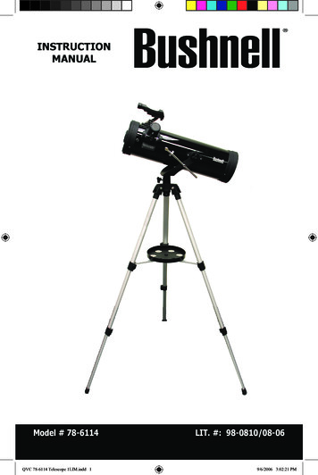
Segmented Beryllium Primary Mirror areal density 3 times less than HST Technologies for JWST mirror manufacturing and polishing broadly applicable for future space telescopes Must fold up to fit inside rocket fairing, breaking the limitation on mirror diameterComposite structure to hold mirrors and instruments Behavior must be known to 40 nanometers ( 1/10,000 of a human hair) Must maintain this stability while being cooled over 400 degreesCryogenic Application Specific Integrated Circuit (ASIC) JWST ASIC already flying in space: Installed on Hubble Servicing Mission 4 to repair the failed Advanced Camera forSurveys (ACS) instrumentMicro-Shutters 100,000 computer controlled shutters, each the width of a human hair First Mirco-ElectroMechanical (MEMS) devise for science to be flown in space Early research on MEMs devised for JWST helped develop analogous instrument for ground-based telescopesSunshield Membranes Lightweight deployable sunshield the size of a tennis court to passively cool JWST telescope and instruments 5 thin separated membrane layers (each less than half the thickness of a piece of paper) Providing a 500 F temperature difference (equivalent SPF of 1,000,000) Advanced Near Infrared Detectors Advanced Mid-Infrared Detectors Cryo-cooler for Mid-Infrared Instrument Mirror Phasing and Control Software Heat Switches3
TECHNOLOGICAL ADVANCESMirror Support StructureStructures hold mirrors andscience instruments superstable, behavior must be knownto 38 nanometers ( 1/10,000thof a human hair!)Segmented Beryllium MirrorAdvanced Near Infrared detectorsMirrors so smooth that if “stretched” to the size ofthe continental US largest deviation from perfectionwould be 2 inches in height.Advanced Mid-Infrared detectors18 mirror segmentscomputer controlled tooperate as one mirror inspaceCryogenic ASICsUltra-sensitive detectors on JWSTcould see a single candle on theMoon from 1 million km.Green borders denoteactual spaceflighthardware, red bordersare test equipmentMirror phasing and controlMicroshutters 100,000 computer controlled shutters,the width of a human hair enable optimalscience returnSunshield Membrane5 thin membranes (each less than half the thickness of a piece of paper)protect the side in the extreme of cold space from the warm sunlit side[Equivalent Sun Protection Factor (SPF) of 1,000,000]4
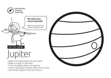
The Final Acceptance Test Completes a Decade plusDevelopment Effort to Make JWST anced Mirror System Demonstrator (AMSD)Collaboration among 3 government agencies15Kg/m2, 1.2M diameter liumOnset ofAMSD Phase 1: AMSD Phase 2:James Webb8 Mirror Designs3 mirrors developedSpace TelescopeSubscaleBerylliumMirror Demonstrator(SBMD):.5 meter diameter,Low Areal Density Mirrors Identifiedas Key Enabling Technology for25 Square Meter Space TelescopeTechnologyReadinessLevel-6 Demonstrated:All key requirements andenvironments demonstratedAMSD Phase 3/Six Sigma StudyBe manuf. and process improvementsOTE OpticsReviewEngineering Design Unit.(OOR):BerylliumSelectedPM Manufacturing of 18 segmentsMachiningFacilityComplete Cryo TestingPrimary MirrorSegment AssembliesCompletePolishingFacilityComplete5
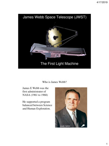
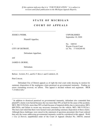
Coated Primary Mirror Segment Assembly6
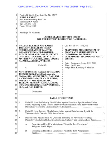
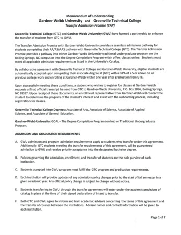
Primary Mirror Assembly7
8
99
Mirrors CompletedMirrorElementRMS Surface Figure Error [nm]MeasuredUncertaintyTotalRequirement18 PrimarySegments(Composite tiary17.514.79.48.719.917.123.217.5Fine Steering Mirror01/26/201210
Completed Mirrors in Storage11
Flight Backplane Bonding StatusStatus as of: 11/30/2011 PMBSS Center Section fabrication and assembly Piece part fabrication - 100% complete Assembly bonding continuing @ 87% completePMBSS Center Section Assembly - in process: Not Assembled: Assembled: Recently assembled sincelast PMRCenter Section Assembly Locations12
Sunshield Template Membrane Work On-Going Template Layer 3 build and testingcomplete. Packed for shipping toNGAS Layer 3Shape measurements show RMSerror of 0.71 in. versus requirementof 0.75 in. Template Layer 5 seamed andcatenaries/fill regions installed.Currently getting edge features andgrommets installed Template Layer 4 fully seamedLayer 5Preliminary Template Layer 3 Scan01/19/201213
MIRI Cryo Cooler Overview Provides the needed active cooling to 6K for the MIRI detectors and OpticalAssembly Thefirst long life, 6K mechanicalcooler Implementedas hybrid multi-stagemechanical Pulse-Tube JouleThomson (JT) Cooler Challengingarchitecture with the 6Kload several ( 10) meters from thecompressors14
Technical Issue – Detector Degradation Flight detector testing shows a degradation in pixel operability Impacts NIRCam, NIRSpec, and FGS Detector FRB complete Found that detector degradation is caused by a design flaw which impacted itsperformance The Detector FRB found that the detector degradation is caused by a design flaw in the barrier layer of thepixel interconnect structure, degrading its performance The flawed barrier layer design makes the detectors vulnerable to migration of indium from the indium bumpinterconnect into the detector structure Determined manufacturing and/or post-manufacture handling process changes areappropriateDefined tests needed to screen-out degradation prone parts and insure thecontinued integrity of flight partFabrication of next generation detectors for testing (Jan-April) is underway Decision for the detector swap will be in March 201215
Technical Issue – Detector Degradation ETU Detector Status Teledyne has recently completed testing Short Wave (SW) detectors fabricatedfor their ground-based astronomy customers. Several of these SCAs were fabricated using new bake-stable process which willcorrect degradation issue seen on JWST detectors– Are similar to the JWST SW parts, thereby providing the first performance test of JWST-likeparts using the new process Test results show the new process does not appear to have any adverse effect onscience performance Still on schedule to receive the first Mid-Wave and SW detectors in early January Total of 22 SCAs to be delivered (Jan-April) for testing– Testing starts at Teledyne in Jan, then proceeds to University of Arizona and the GSFCDetector Characterization Lab in Feb.16
JWST Tech Spin OffsNew Optical Measurement Devices The need to accurately measure the shape of the JWST mirrorsrequired significant improvements in wavefront sensingtechnology (Scanning Shack-Hartman Sensor) Has enabled a number of improvements in measurementtechnology for measurement of human eyes, diagnosis of oculardiseases and potentially improved surgery Eye doctors can now get much more detailed information aboutthe shape of your eye in seconds rather than hours Four patents have been issues as a result of these innovationsCryogenic ASIC JWST developed a low-noise, cryogenic ASIC to convert theanalog signals from the near-IR detectors to digital Same design used on ASIC now being used in the AdvancedCamera for Surveys which was repaired during the HST SM-4servicing mission “future heritage”17
JWST Tech Spin OffsLaser Interferometers utilizing High SpeedOptical Sensors JWST needed to make measurements ofmirrors and composite structures withnanometer precision in cryogenic vacuumchambers (with vibrations from pumpingsystems a constant problem) JWST provided 4D its first commercial contractto develop the PhaseCam interferometersystem 4D Technology Corp has developed severalnew types of high-speed test devices thatutilize pulsed lasers that essentially freeze outthe effects of vibration 4D has gone on to generate over 30 M inrevenue from a wide range of applications inastronomy, aerospace, semiconductor andmedical industries based on the technologiesdeveloped for JWST18
Implementing the New Baseline Completed the replan (9/23/2011) with an October 2018 launch date Plan has adequate cost and schedule reserves consistent with ICRP recommendation Additional 44M in FY11 was approved by Congress FY12 budget approved by Congress with full funding for JWST FY13 PBR fully funds the new baselineRecent Accomplishments All flight optics have been cryo tested and meet requirements Completed the Aft Optic System integration and alignment Primary Mirror Backup Support Structure center section nearly complete (94% of bonding is complete) Sunshield full scale Engineering Development Unit for layer #3 testing completed with good results Instrument deliveries to GSFC begin in Spring 2012Brought back in work with additional FY11 funding and FY12 budget Accelerated: Backplane Support Frame (BSF) by 4 months, completion of PMBSS by 4 months, start ofWings by 18 months, end of Flight Optics Integration by 4 months Still have 13 month of funded schedule reserve on critical pathInstrument deliveries slipped moving ISIM delivery to OTIS by 5 months (31 months to 26 months) Even with Detector change out, still have 11 months slack for ISIM delivery to OTIS ETUs for NIRSpec and NIRCam will be used in ISIM Cryo Test 1(all have flight hardware for CT 2 3)JWST made great progress in FY11 and continues to do so in FY12, achievingmilestones within cost and schedule and executing to the new baseline19
Hardware Fabrication Completion PercentagesPrimary Mirror SegmentsPrimary Mirror Support StructureAft Optics System95%100%100%Science Instrument Module& Science Instruments100%90%Secondary MirrorSecondary SupportsGreen borders denoteactual spaceflighthardware images, redborders are testequipmentAs of 1/13/201240%25%80%Sunshield MembranesSpacecraft Bus20
Master Schedule2010JWST 2CDRCCA,SC Panel Prop SSInteg Integ Integ434MOROTEStart EDU3rd Cryo TestDel PFPMSA1stBatchPrimary Mirrors84910412BSF Assy Start2 4PF OpticsInteg32PF SMSS/StrutIntegLastBatch81171149SC Test8 10OTIS I&T7Flt OpticsInteg4122271234PSR8FRR/KDP-IVSC/OTE I&T9FY19451LRD1023ORR49Launch Site9 1027327Flight OTE StructurePMBSSAssy/TestWing Assy Start41SIR KDP-DIntegration & TestJSC CH A PF Install/GSE InstallTest2019FY183TRRMajor Mission Milestones2018FY174Flight Structure (PMBSS)11TemplateMembrane Fab3Flt MembraneMRR26Flt Membrane FabSunshield10Astro Tube Fab244GSE Design/FabStructure Mfg & Test9 11461212SpacecraftSC Panel &SC StructureCDRStartI&TISIMI &TETU Del7NIRSpec1STM Del114824326513 Months of Funded Critical Path Slack6 Months at Observatory I&T3 Months at OTE I&T4 Months of Embeded Slack in OTE ActivitiesAfter testing of replacement detectors, theISIM flow will be updated to show thedetector change-out strategy.Flt Del4ETU DelNIRCamFlt Del5 ETU Del8FGS5212Flt Del4SCStructure8MIRI36Del Flt ISIMto OTISPERInteg Skeleton& Membrane4Fit CheckCHAFlt Del6Flt CHAETUCCACCES/CELS Mock-upFltFlt CCA/CCECCA/CCE(Spares)Flt CTACryo Cooler SystemCCTS Build 2.348CCTS Build 2.410102CCTS Build 2.517Begin End-to-EndGrnd/Flt Seg Testing41910ComissioningGround SegmentLaunch SegmentSafety Submittal 2LV Lift Performance Verified8Flight Adapter Fit Check1210CLA647104Safety Submittal 3 RAMFAriane AdapterDCI Release 2 (Final)Flight Adapter &115 67Shogun EquipCLA7CLA8LV ReadinessReview21(RAV)3912479REV -
Work-To-Go (FY12 to Launch and Commissioning)Relative proportion of project funding to-go% work on this element to-go22
Optical telescope element Simulator (OSIM) IntegrationOn Track for Cryo Verification mid-April 2012ISIMStatus as of: 1/31/122323
Telescope Assembly Ground Support EquipmentHardware has been installed at GSFCapproximately 8 weeks ahead ofscheduleAmbient Optical Alignment Stand CompleteLanding a mirror onto backplanesimulator01/19/201224
OTE Testing – Chamber A at JSCNotice people for scaleWill be the largest cryo vacuum test chamber in the world25
Center of Telescope Curvature Optical Test EquipmentMulti WavelengthInterferometer (MWIF)Displacement MeasuringInterferometers (DMIs)Pressure Tight Enclosure(PTE)Hexapod ActuatorNull AssemblyHologramBeam Splitter andCASS Camera26
BACKUP27
James Webb Space Telescope (JWST) goesbeyond Hubble and other space telescopes byseeing things that they cannot see How did the universe make galaxies?Are there other planets that can support life?How are stars made?JWST is about beginnings: the beginning ofgalaxies, the beginning of stars, the beginningof planets and life.First LightPlanets and the Origins ofLifeThe Assembly of GalaxiesBirth of Stars andPlanets28
29
Deployed Configuration6.100 m6.600 m21.197 mStowed Configuration 10.661 m 4.472 m 14.625 mOptical Telescope Element (OTE) diffraction limited at 2 micron wavelength.– 25 m2 , 6.35 m average diameter aperture.– Instantaneous Field of View (FOV) 9’ X 18’.– Deployable Primary Mirror (PM) and Secondary Mirror (SM).– 18 Segment PM with 7 Degree of Freedom (DOF) adjustability on each.Integrated Science Instrument Module (ISIM) containing near and mid infrared cryogenic scienceinstruments– The Near-infrared camera functions as the on-board wavefront sensor for initial OTEalignment and phasing and periodic maintenance.Deployable sunshield for passive cooling of OTE and ISIM.Mass: 6530 kg .Power Generation: 2000 Watts Solar Array.Data Capabilities: 471 Gbits on-board storage, 229 Gbits/day science data.Science Data Downlink: 32 Mbps.Life: 5 years [Designed for 11 years (goal) of operation].30 30
Technologies for JWST mirror manufacturing and polishing broadly applicable for future space telescopes Must fold up to fit inside rocket fairing, breaking the limitation on mirror diameter Composite structure to hold mirrors and instruments Behavior must be k