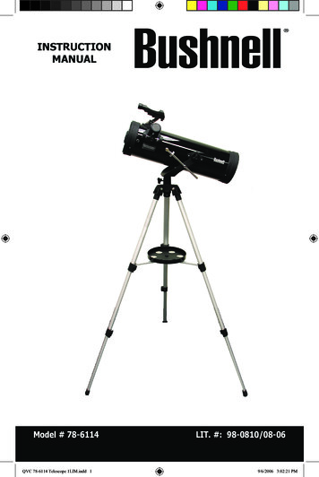
Transcription
Instruction ManualDS-114ATReflecting TelescopeMeade Instruments Corporation
Reflecting Telescopes use a concave primary mirror to collect lightand form an image. In the Newtonian type of reflector, light is reflected by a small, flat secondary mirror to the side of the main tube forobservation of the image. Light is collected by a concave mirror andbrought to a focus at F.SecondaryMirrorConcaveMirrorReflecting TelescopeFEyepiece
CONTENTSQuick-Start Guide . 4Telescope Features . 7Autostar Features . 8Getting Started .10Packing List .10How to Assemble Your Telescope .10Some Notes About the Dual-Motor System .11The Viewfinder .11Focusing the Viewfinder .11Aligning the Viewfinder .12Choosing an Eyepiece .12The Barlow Lens .12Observing .13Observing by Moving the Telescope Manually .13Terrestrial Observing .13Observing Using Autostar's Arrow Keys .13Slew Speeds .14Observe the Moon .14Astronomical Observing .14Tracking an Object Automatically.14Alt/Az Home Position .15Moving Through Autostar’s Menus.15Initializing Autostar .15Training the Drive .16Observe a Star Using Automatic Tracking .17Easy (Two-Star) Align .17Two-Star Alt/Az Alignment .18One-Star Alt/Az Alignment .18Go To Saturn .19Take a Guided Tour .19Basic Autostar Operation.20Autostar Navigation Exercise .20Entering Numbers and Text into Autostar .21Navigating Autostar .21Adjusting the Speed of a Scrolling Message .21Menus and Menu Options .22Complete Autostar Menu Structure .22Object Menu.22Event Menu .23Glossary Menu .24Utilities Menu .24Setup Menu .25Caring for Your Telescope .28Collimation .28Specifications .30Optional Accessories .31Meade Customer Service .31Appendix A: Locating the Celestial Pole .32Appendix B: To Find Objects Not in the Database .33Appendix C: Observing Satellites .34Basic Astronomy .35WARNING!Never use a Meade DS-114AT Telescopeto look at the Sun! Looking at or near theSun will cause instant and irreversible damage to your eye. Eye damage is often painless, so there is no warning to the observerthat damage has occurred until it is too late.Do not point the telescope or its viewfinderat or near the Sun. Do not look through thetelescope or its viewfinder as it is moving.Children should always have adult supervision while observing.CAUTION:Use care to install batteries as indicated bythe battery compartment. Follow batterymanufacturer's precautions. Do not installbatteries backward or mix new and used batteries. Do not mix battery types. If these precautions are not followed, batteries mayexplode, catch fire, or leak. Improperlyinstalled batteries void your Meade warranty.If you are anxious to use your DS-114ATTelescope for the first time, before athorough reading of this instruction manual, see the QUICK-START GUIDE on page 4. The name “Meade” and the Meade logo aretrademarks registered with the U.S. Patent Officeand in principal countries throughout the world. Allrights reserved. 2001 Meade Instruments Corporation.3
QUICK-START GUIDEThis Quick Start procedure explains how to set up your DS-114AT for manual viewing. If you wish to make observationsusing the Autostar handbox, please turn to HOW TO ASSEMBLE YOUR TELESCOPE, page 10 and take the time and carenecessary to assemble all the components that are supplied with this telescope.1.Remove the optical tube and tripod from the giftbox.Perform this setup on a flat, stable surface. It is recommended that you perform this operation in the daytime or in bright light the first time you assemble the telescope.The optical tube assembly is shipped with the cradlerings, yoke mount, and tripod attached. Carefullyremove the assembly from the box. Lay the assemblyon the floor.12.Remove the optical tube from the mount.The optical tube is shipped oriented the wrong directionin the yoke mount for observing—you must remove thetube from the mount and turn it around 180 .Loosen the cradle ring lock knobs and move the knobsout of the way so that you can open the cradle rings.Once the rings are open, remove the optical tube fromthe cradle rings.23.AStand the tripod and orient the cradle rings.Stand the tripod on a flat surface and gently pull thelegs apart to a fully open position. Turn the cradle ringsso that the ring base is horizontal (parallel) to theground. Tighten the alt lock (A) to a firm feel, so therings remain in that position.34
4.Attach and balance the optical tube.Turn the optical tube around and replace it into the cradle rings. Fasten the cradle rings lock knobs so thatthey only hold the optical tube loosely; do not tightenthe lock knobs yet. Note the optical tube's and theyoke's orientation in photo.Slide the tube back and forth until you find a positionwhere the tube remains horizontal (i.e., without tippingup or down). Then tighten the cradle rings lock knobs toa firm feel.45.BInsert the eyepiece.Remove the supplied 25mm eyepiece (B) from its container and place it into the eyepiece holder. Tighten thethumbscrews (C) to a firm feel only. Remove the dustcover from the end of optical tube assembly. Use thefocus knobs (D) to bring objects into focus.CD56.Adjust tripod.Adjust the height of the tripod by lifting the clip on eachleg and extending the sliding inner section of each tripod leg to the desired length. Then press the clip backagainst the leg to lock in place.67.Sight along the tube.Sight along the side of the telescope's main tube tolocate an object and then observe through the eyepiece.7If you wish to attach the viewfinder, see page 10.If you wish to initialize Autostar, see page 15.If you wish to align the telescope, see page 17.If you wish to use Autostar to automatically viewobjects, see page 19 for some examples.5
107964533Fig. 1c: Cradle Rings LockKnobs (on opposite side).28111232212211319141820171516ABCDEFFig. 1b (Inset): Computer Control Panel.(A) LED(B) 12V Port(C) Handbox Port(D) AZ Port(E) ALT Port(F) AUX PortFig. 1: DS-114AT Series Telescope.6
TELESCOPE FEATURESThe DS-114AT telescope has a variety of useful features. Be sure to become acquainted withall of these controls before you begin making observations through the telescope. Want to learnmore about theviewfinder?See pages 10through 12. Focus Knobs: Move the telescope’s focus drawtube in a finely-controlled motion to achieveprecise image focus.Eyepiece Holder: Holds the eyepiece in place.Eyepiece Holder Thumbscrews (2): Tighten the eyepiece in place. Tighten to a firm feel only.Eyepiece: Place one of the supplied eyepieces into the eyepiece holder (2, Fig. 1).Viewfinder: Provides an easier way to initially sight objects than the main telescope eyepiecewhich has a narrower field of view.Viewfinder Alignment Screws (4): Adjust these screws to align the viewfinder.Viewfinder Alignment Bracket: Attaches the viewfinder to the telescope (11, Fig. 1).Alt Indicator: Displays the angle (in degrees) of the altitude of the optical tube.Cradle Rings (2): Hold optical tube securely in place.Want to learnmore aboutcollimation?See pages 29and 30.Cradle Ring Lock Knobs (2): Tighten to a firm feel to hold the optical tube securely inplace. Fig. 1c depicts a cradle ring clamped in place by one of the lock knobs and one ofthe lock knobs hanging loose.Optical Tube: The main optical component that gathers the light from distant objects andbrings this light to a focus for observation with the eyepiece.Primary Mirror Cell: Contains the optical tube's primary mirror and 3 screws that are usedin a collimation adjustment. Note: Do not remove the piece of felt from the cell. Want to learnmore aboutAutostar'sbuttons?See pages 8and 9.Autostar'smenus?See pages 22through 27. Alt (Vertical) Gear and Motor: Moves the telescope along the vertical axis.Battery Pack: Supplies power to the assembly. Install 10 user-supplied AA batteries.Autostar: Autostar is able to control nearly all the functions of the telescope.Tripod Legs: To use, spread the legs as far as they will open. Adjust the height of the tripod by lifting the clip on each leg and extending the sliding inner section of each tripod legto the desired length. Then press the clip back against the leg to lock in place.Accessory Tray: Conveniently holds extra eyepieces, Autostar, and other accessories.Az (Horizontal) Gear and Motor: Moves the telescope along the horizontal axis.Az Lock: Controls the manual horizontal movement of the telescope. Turning the Alt lockcounterclockwise unlocks the telescope enabling it to be freely moved by hand on the horizontal axis. Turning the Alt lock clockwise (to a firm feel only) prevents the telescope frombeing moved manually and engages the vertical motor drive clutch for Autostar operation.Computer Control Panel (Fig. 1b)A. LED: The red power indicator light illuminates when power (i.e., the battery pack)is supplied to the Autostar handbox and to the telescope’s motor drive.B. 12V: Plug the battery pack into this port.C. Handbox (HBX) Port: Plug the #494 Autostar handbox into this port.D. Azimuth (AZ) Port: Plug the Az motor into this port.E. Altitude (ALT) Port: Plug the Alt motor into this port.F. Auxiliary (AUX) Port: Provides connection for Meade accessories.21 Yoke Mount: Along with the cradle rings, holds the optical tube assembly (11, Fig. 1). 22 23 Alt Lock: Controls the manual vertical movement of the telescope. Turning the Alt lockcounterclockwise unlocks the telescope enabling it to be freely tilted by hand on the vertical axis. Turning the Alt lock clockwise (to a firm feel only) prevents the telescope frombeing moved manually and engages the vertical motor drive clutch for Autostar operation.Dust Cap: Pull to remove the dust cap from the front lens of the telescope.Note: The dust cap should be replaced and the power turned off to the telescopeafter each observing session. Verify that any dew that might have collected duringthe observing session has evaporated prior to replacing the dust cap.7
AUTOSTAR FEATURESControl of the DS-114AT Series Telescopes is throughthe operation of the #494 Autostar handbox. Nearly allfunctions of the telescope can be operated with just afew pushes of Autostar’s buttons. Some of the majorfeatures of Autostar are: Automatically move the telescope to any of the1400 objects stored in the database or manuallyenter the astronomical coordinates of any celestialobject. Take a guided tour of the best celestial objects toview on any given night of the year. Access a glossary of astronomical terms. Calculate which eyepiece to use for optimum viewing of a celestial object.Autostar has soft-touch keys and the LCD (LiquidCrystal Display) is backlit with a red LED (LightEmitting Diode) for easy viewing in the dark.NOTE: Autostar does not require batteries; thetelescope’s batteries supply power to Autostar.TIP: When a message is scrollingacross the display,press and hold the UpArrow key to increasethe scrolling speed orpress and hold theDown Arrow key todecrease the scrollingspeed. Top line: Displays the menu or category name.Bottom line: Displays a menu option or information about a subject.ENTER Key: When an option is displayed, press ENTER to enable the choice. When amenu is displayed, press ENTER to access the next menu or data level in the Autostardatabase. ENTER is similar to the RETURN key on a computer. See MOVING THROUGHAUTOSTAR'S MENUS, page 15 and MENUS AND MENU OPTIONS, page 22.NOTE: If ENTER is pressed for two seconds or more and then released, Autostaremits a beep and “ENTER to Sync” is displayed. If the "ENTER to Sync" feature isaccessed by mistake, press MODE to return to the previous screen. See HIGHPRECISION, page 26, for more details about this feature. DEFINITION:Throughout this manual, you will noticethe term "Alt/Az."Alt/Az is frequentlyused to refer toAltitude (vertical) andAzimuth (horizontal).Alt/Az is just one ofmany methods usedby amateurastronomers to helplocate stars in thenight sky.2-Line LCD: Displays Autostar menu and help information. Fig. 2: #494 Autostar Handbox.MODE Key: When a menu is displayed, press MODE to return to the previous menu or datalevel in the Autostar database. MODE is similar to the ESCAPE key on a computer.NOTE: Pressing MODE while in the “Select Item” level moves Autostar to the topmost screen: “Select Item: Object.”NOTE: If MODE is pressed and held for two seconds or more, the following information is then available using the Scroll keys (6 and 7, Fig. 2): Right Ascension and Declination (astronomical) coordinates Altitude (vertical) and Azimuth (horizontal) coordinates Local Time and Local Sidereal Time (LST) Timer and Alarm StatusPress MODE again to return to the previous menu. GO TO Key: Moves the telescope to the currently selected object. While the telescope ismoving, the operation may be aborted at any time by pressing any key except GO TO.Pressing GO TO again resumes the operation.The GO TO key also allows you to perform a "spiral search." A spiral search is useful whenthe telescope is commanded to go to an object, but that object is not visible in the eyepieceafter the telescope finishes its search. (This sometimes occurs during the alignment procedure.) Press GO TO when the slew is finished and the telescope starts slewing in a spiral pattern at a very slow speed around the search area. Look through the eyepiece andwhen the object does become visible, press MODE to stop the spiral search. Then use theArrow keys to center the object.8
Want to learnmore aboutslew speeds?See page 14. Arrow Keys: Move the telescope in a specific direction (up, down, left, and right), at anyone of nine different slew speeds.The Arrow Keys can also be used to scroll through the letters of the alphabet and numerical digits. The Down Arrow key starts with the letter "A" and the Up Arrow key starts withthe digit "9." The Left and Right Arrow keys moves the cursor left and right across the LCDdisplay. , Scroll Keys: Access options of the menu displayed on the top line of the screen.Options within the menu are displayed, one at a time, on the second line. Press the Scrollkeys to move through the options. Press and hold a Scroll key to move quickly through theoptions, or to change scroll speeds of text.The Scroll keys also scroll through the letters of the alphabet and numerical digits.Tip: When a message is scrolling across the display, press and hold the Up Scrollkey to increase the scrolling speed, or press and hold the Down Scroll key todecrease the scrolling speed.NOTE: The Scroll Down key and the Down Arrow key move forward through thealphabet & digits (A to Z, 0 to 9). The Scroll Up key and the Up Arrow key movebackward (Z to A, 9 to 0). Common symbols are also available in the list.Speed/? Key: Press the Speed/? key to cycle through the nine slew speeds that move thetelescope. Each time the Speed/? key is briefly pressed, the current speed will be shownfor about two seconds on the display.The Speed/? key also accesses the "Help" file. "Help" provides on-screen information forwhatever task is currently active.NOTE: Pressing the Speed/? key very briefly changes the slew speed. Holdingdown the Speed/? key longer (one to two seconds) accesses the Help function.If you have a question about anAutostar operation (e.g., INITIALIZATION, ALIGNMENT, etc.), hold downthe Speed/? key and follow the directions that scroll on the second line ofthe LCD screen. When a word appearsin [brackets], press ENTER to accessthe Autostar Glossary. A definition ormore detailed information is displayed.Press MODE to return to the scrollingAutostar Help display.When satisfied with the Help provided,press MODE to return to the originalscreen and continue with the chosenprocedure.Coil Cord: Plug the Autostar coil cordinto the HBX port (C, Fig. 1b) of thecomputer control panel.Join an Astronomy ClubAttend a Star PartyA fun way to learn more about astronomy is tojoin an astronomy club. Check your local newspaper, school, library, or telescope dealer to findout if there’s a club in your area.At club meetings, you will meet other astronomyenthusiasts with whom you will be able to shareyour discoveries. Clubs are an excellent way tolearn more about observing the sky, to find outwhere the best observing sites are, and to compare notes about telescopes, eyepieces, filters,tripods, and so forth.Often, club members are excellent astrophotographers. Not only will you be able to studyexamples of their art, but you may even be ableto pick up some “tricks of the trade” to try out onyour DS-114AT telescope.Many groups hold regularly scheduled star parties at which you can observe with many different telescopes and examine other pieces ofastronomical equipment. Magazines such asSky & Telescope and Astronomy print schedulesfor many popular star parties around the UnitedStates and Canada.9
GETTING STARTEDPacking ListAssembling the telescope for the first time requires only a few minutes. When first opening thepacking box, note carefully the parts listed on your giftbox.How to Assemble Your TelescopeThe telescope attaches directly to the tripod. The telescope in this way is "mounted" in an“Altazimuth” (“Altitude-Azimuth,” or “vertical-horizontal”) format. The telescope mounted this waymoves along the vertical and horizontal axes, corresponding to the astronomical axes known asDeclination (vertical) and Right Ascension (horizontal).Perform this setup on a flat, stable surface. It is recommended that you perform this operationin the daytime or in bright light the first time you assemble the telescope.Fig. 3 Remove assemblyfrom the giftbox.1.Remove the optical tube and tripod from the giftbox: The optical tube assembly isshipped with the cradle rings (9, Fig. 1), yoke mount (21, Fig. 1), and tripod attached.Carefully remove the assembly from the box. Lay the assembly on the floor.2.Remove the optical tube from the mount: The optical tube (11, Fig. 1) is shipped oriented the wrong direction in the yoke mount for observing—you must remove the tube fromthe mount and turn it around 180 .Loosen and unlatch the cradle ring lock knobs (10, Fig. 1) so that you can open the cradlerings (9, Fig. 1). Once the rings are open, remove the optical tube from the cradle rings.Carefully note the orientation of the tube, so that you can rotate it 180 later on when youreplace it in the rings.Fig. 4: Adjust the cradlerings.3.Stand the tripod and adjust the cradle rings: Stand the tripod on a flat surface and gently pull the legs (16, Fig. 1) apart to a fully open position. Turn the cradle rings so that thecradle ring base is horizontal (parallel) to the ground. Tighten the alt lock (22, Fig. 1), sothe rings remain in the horizontal position.4.Attach the utility tray to the tripod: Place one of the tray's flanges around one edge of atripod leg and then pull the tray around until the other flange snaps in place (Fig. 5). Theutility tray (17, Fig. 1) can be pushed up or down the tripod leg to a convenient height.5.Attach and balance the optical tube: Turn the optical tube around 180 and replace it intothe cradle rings. Fasten the cradle rings lock knobs (10, Fig. 1) so that they only hold theoptical tube loosely; do not tighten the lock knobs yet.Slide the tube back and forth until you find a position where the tube remains horizontal(i.e., without tipping up or down). Then tighten the cradle rings lock knobs to a firm feel.Fig. 5 Attach tray to thetripod:6.Attach the Alt (vertical) motor to the Alt gear: Place the knurled ring of the motor assembly over the Alt gear. Note that three small plastic tabs project outwards from the face ofthe gear (Fig. 7). These "locator" tabs fit into the mating slots inside the knurled ring.Wiggle the motor assembly over the gear assembly until the motor slips into place. Threadthe knurled ring over the mating threads of the gear assembly to lock the motor. See Fig.8. Tighten to a firm feel only.7.Attach the Az (horizontal) motor to the Az gear: Attach the Az motor assembly to thethe Az gear using the procedure described in step 6. See Fig. 9.8.Connect the motor assembly cords: Plug the cord from the alt motor assembly into the Altport (E, Fig.1b) of the computer control panel. Plug the cord from the az motor assembly intothe Az port (D, Fig.1b) of the computer control panel.9.Attach the viewfinder bracket: Use a Phillips-head screwdriver to thread the two attachmentscrews in the viewfinder bracket (these screws are placed inside the bracket at the factory) intothe mating threads located on the optical tube (Fig. 10).Fig. 6: Attach and balance the optical tube.Fig. 7: Motor (left) andgear (right) assembly.Note the slots and thelocator tabs.10. Attach the viewfinder tube: Carefully remove the rubber eyecup from the viewfinderbefore sliding the viewfinder into the bracket. Then slide the viewfinder, eyepiece-end first(the end to which the rubber cup was attached) into the viewfinder bracket. Replace therubber eyecup. Tighten the four alignment thumbscrews (6, Fig. 1 and Fig. 11) to a firmfeel to hold the viewfinder in the bracket.11. Insert the eyepiece: Remove the supplied 25mm eyepiece from its container and place itinto the eyepiece holder (2, Fig. 1). Tighten the thumbscrew (3, Fig. 1) to a firm feel only.10
12. Connect Autostar: Plug the coil cord of the Autostar Controller into the HBX port (C,Fig.1b) of the computer control panel.WARNING: Make sure you plug in Autostar before you plug in the battery pack.NOTE: Autostar does not require batteries; the telescope’s batteries supply powerto Autostar.13. Insert batteries: Install 10 AA user-supplied batteries into the battery pack (Fig.12), oriented as shown on the diagram on the battery slots of the battery holder.Fig. 8: Attach Alt motor.CAUTION: Use care to install batteries as indicated by the battery compartment.Follow battery manufacturer's precautions. Do not install batteries backwards ormix new and used batteries. Do not mix battery types. If these precautions are notfollowed, batteries may explode, catch fire, or leak. Improperly installed batteriesvoid your Meade warranty. Always remove the batteries if they are not to be usedfor a long period of time.14. Connect battery pack: Plug the battery pack into the 12V port (B, Fig.1b) of the computer control panel. Attach the pack to one of the tripod legs using the Velcro fastener or setit on the utility tray.Fig. 9: Attach Az motor.15. Adjust tripod: Adjust the height of the tripod to a convenient viewing height by lifting theclip on each leg and extending the sliding inner section of the leg to the desired length.Then press the clip back against the leg to lock in place.15. Remove the dust cover: Pull out the dust cover (23, Fig. 1) from the optical tube.Assembly of the telescope is now complete.Some Notes About the Dual-Motor System Fig. 10: Attach the viewfinder bracket to the opticaltube. Fig. 11: Attach the viewfinder tube to bracket and tighten thumbscrews. For the motors to be operational, the Az and Alt lock-knobs (19, Fig. 1) and (22, Fig. 1)must be in their locked positions. Firm-feel tightening of these locks is sufficient. Do notovertighten. If these are not sufficiently tightened, Autostar may display a motor fault message.When setting up the telescope, always plug in the battery pack to the control panel last,after plugging in the two motors and Autostar. Connecting the battery pack to the controlpanel before the motors and Autostar are connected may result in false electrical signalsbeing sent to the motors, causing them to malfunction. In this case unplug the battery packfrom the control panel, wait a few seconds, and plug the battery pack back into the controlpanel. This operation clears the motors of any false signals.Take care that cords do not become wrapped around the telescope; keep the cords “loose”at all times. Do not allow the telescope to slew into the tripod or other fixed object. Do nottouch or hold the telescope tube while it is moving.If the motors stall or do not have sufficient power to move the telescope, place fresh batteries in the battery pack. Long-life alkaline batteries are recommended.The first time you initialize your system, make sure you train the drives. This allowsAutostar to move the telescope precisely to objects. See page 16 for detailed infofrmation.The ViewfinderFig. 12: Insert 10 AA batteries into battery pack.Because the main telescope has a fairly narrow field of view, locating objects directly in themain telescope can sometimes be difficult. The viewfinder (5, Fig. 1) is a small, wide-field telescope with crosshairs that permits you to locate objects more easily. When the viewfinder andoptical tube are aligned to each other, both point to the same position in the sky. An object located in the viewfinder is therefore also positioned within the field of the main telescope. Beforealigning the viewfinder to the optical tube, focus the viewfinder.Focusing the Viewfinder:1.Turn the viewfinder eyepiece on its internal thread. Generally a few turns are sufficient toachieve proper focus.11
ViewfinderTelescopeEyepieceAligning the Viewfinder:It is recommended that you perform steps 1 through 4 of this procedure during the daytime andstep 5 at night.1.A. Not alignedB. Aligned2.3.4.Fig. 13: Aligning theviewfinder. Note that objectsappear upside-down andreversed left-for-right whenobserved in the viewfinder.5.Loosen the Az lock (19, Fig. 1) and the Alt lock (22, Fig. 1) by turning the locks about oneturn counterclockwise, permitting the telescope to move freely on its axes.If you have not already done so, place a low-power (e.g., 25mm) eyepiece in the eyepieceholder of the main telescope (2, Fig. 1) and point the telescope at an easy-to-find landobject (e.g., the top of a telephone pole). Turn the focuser knob (1, Fig. 1) so that the imageis sharply focused. Center the object precisely in the main telescope’s field of view.Re-tighten the Az lock (19, Fig. 1) and the Alt lock (22, Fig. 1).Now, looking through the viewfinder, turn some or all of the viewfinder’s alignment screws(6, Fig. 1) until the viewfinder’s crosshairs point precisely at the same object as centeredin the main telescope. The viewfinder is now aligned to the main telescope. The right-handimage in Fig. 13A shows an object centered in the main telescope before the viewfinder(the left-hand image) has been aligned to the main telescope. Fig. 13B shows these sameimages after the viewfinder and main telescope are aligned.Check this alignment on a celestial object, such as the Moon or a bright star, and makeany necessary refinements.Choosing an EyepieceA telescope’s eyepiece magnifies the image formed by the telescope’s main optics. Each eyepiece has a focal length, expressed in millimeters, or “mm.” The smaller the focal length, thehigher the magnification. For example, an eyepiece with a focal length of 9mm has a highermagnification than an eyepiece with a focal length of 25mm.Your telescope comes supplied with a low-powered 25mm eyepiece which gives a wide, comfortable field of view with high image resolution.Fig. 14: Eyepiece andfocuser assembly.Low power eyepieces offer a wide field of view, bright, high-contrast images, and eye relief during long observing sessions. To find an object with a telescope, always start with a lower powereyepiece such as a 25mm. When the object is located and centered in the eyepiece, you maywish to switch to a higher power eyepiece to enlarge the image as much as practical for prevailing seeing conditions.NOTE: Viewing conditions vary widely from night-to-night and site-to-site.Turbulence in the air, even on an apparently clear night, can distort images. If animage appears fuzzy and ill-defined, back off to a lower power eyepiece for a morewell-resolved image.The power (or magnification) of a telescope is determined by the focal length of the telescopeand the focal length of the eyep
This Quick Start procedure explains how to set up your DS-114AT for manual viewing. If you wish to make observations using the Autostar handbox, please turn to HOW TO ASSEMBLE YOUR TELESCOPE, page 10 and take the time and care necessary to assemble all the