Transcription
Building your very firstRadio TelescopeAuthor: Apostolos Spanakis-MisirlisWritten on December 11th, 2019Wish to observe the radio sky without building your own antenna?Visit www.pictortelescope.com to observe with PICTOR for free!
Table of ContentsTable of Contents1Introduction: What even is radio astronomy?2But why should we observe in radio wavelengths?2What will I be able to observe with my radio telescope?4The 21-centimeter hydrogen line5The superheterodyne receiver5Building our radio telescope7VIRGO: A Spectrometer for Radio Astronomy10When is the best time to observe the hydrogen line?10Example observation11Conclusion12Image attribution notice131
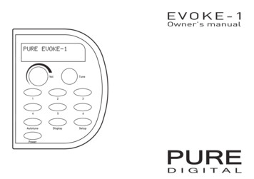
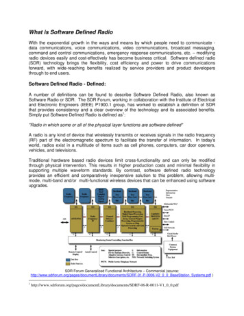
Introduction: What even is radio astronomy?Radio astronomy is a subfield of astronomy that studies celestial objects at radio frequencies.Unlike traditional telescopes that observe the sky in the visible part of the electromagneticspectrum ( 400-700 nm ), radio telescopes observe the sky in wavelengths ranging fromcentimeters to a few meters .Fig. 1: A diagram of the electromagnetic spectrum, showing various properties across the rangeof frequencies and wavelengths.But why should we observe in radio wavelengths?There are several reasons to observe the sky at radio frequencies. The most common reasonradio astronomers point radio telescopes to the sky is to study sources that produce radioemissions : radiation that is invisible to the human eye, but is capable of providing compellinginformation to astronomers & astrophysicists.2
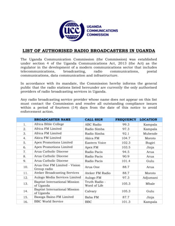
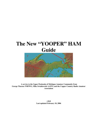
A significant advantage radio astronomers have over IR, UV and high-energy astronomers is theatmospheric window: our atmosphere is completely transparent to radio waves , so we don’tneed to send large radio antennas to space (like we usually have to do with IR/UV/high-energyastronomy satellites) in order to efficiently expose our instruments to the sky.Fig. 2: A diagram showing the amount of absorption of each wavelength of light by the Earth’satmosphere, highlighting the atmospheric windows.It is also worth noting that radio observations can be carried out during both daytime andnighttime , and even under poor weather conditions (e.g. clouds)!Last but not least, we can utilize the techniques of radio interferometry and aperture synthesisusing large arrays of antennas to achieve extremely high (angular) resolution observations ,which is how the first image of a black hole became possible (the combination of several radiotelescopes around the world allowed the Event Horizon Telescope team to create a virtualtelescope the size of the Earth)!3
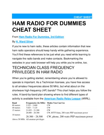
Fig. 3: The Very Large Array (VLA) is one of the most sophisticated radio telescope arrays in theworld, consisting of twenty-seven 25-meter radio antennas that can function as a high-resolutionradio interferometer.What will I be able to observe with my radio telescope?There are plenty of sources in the sky that present radio emissions, including galaxies,supernova remnants, nebulae, radio galaxies, quasars, pulsars, masers and more . However,most radio sources in the sky are very “radio-faint” and require very large aperture antennas tobe detected. The radio telescope described in this document should be capable of detectingradio emissions from the Sun, the Moon, the 21-cm hydrogen line (intergalactic clouds of neutralhydrogen (e.g. spiral arms)), synchrotron radiation originating in the galactic plane and evenCygnus A (radio galaxy) and Cassiopeia A (supernova remnant) if the aperture of antenna is largeenough.4
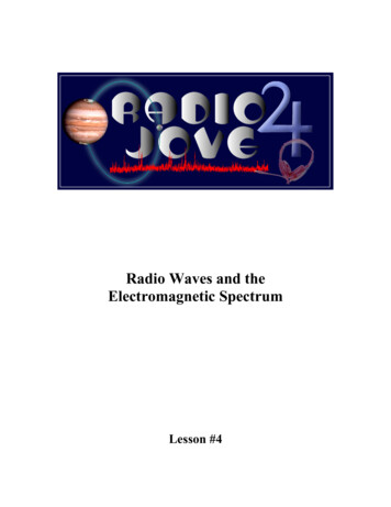
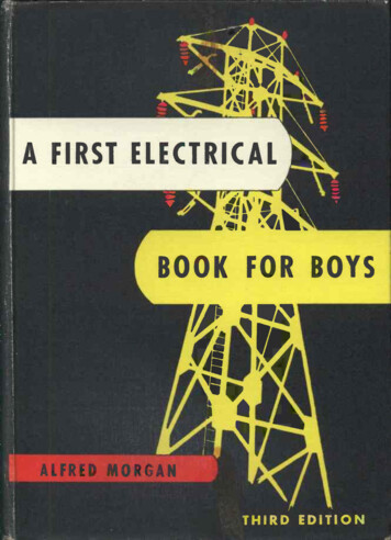
The 21-centimeter hydrogen lineThe hydrogen line refers to the electromagnetic radiation spectral line that is created by achange in the energy state of neutral hydrogen atoms. This electromagnetic radiation is at theapproximate frequency (ν) of 1420.4 MHz , which is equivalent to the wavelength (λ) ofcapproximately 21 cm ( λ ). This wavelength falls within the radio region of theνelectromagnetic spectrum, and it is frequently observed by radio astronomers. The exactmechanism under which hydrogen atoms emit electromagnetic radiation with a wavelength of 21cm is slightly complicated, but it’s not important if you just wish to perform neutral hydrogenobservations (if you’re interested to learn more about how hydrogen atoms can spontaneouslyemit radio waves, take a look here and h ere ).The superheterodyne receiverA superheterodyne receiver is a radio system intended to convert radiofrequency (RF) signals“entering” the antenna into a form that can be conveniently processed and analyzed. This type ofradio receiver is adopted by virtually all modern radio devices, including software-defined radios(SDRs) which will be used in our radio telescope. In this section, the block diagram of thesuperheterodyne receiver is described, with a justification for each component.Fig. 4: Block diagram of a typical superheterodyne receiver found in an SDR.5
The role of an antenna is to convert electromagnetic energy (radio waves) into an alternatingcurrent that is easier to process with modern electronics.An RF filter is used to filter out unwanted interference picked up by the antenna before the signalreaches the RF amplifier , where it is amplified in order to rise above the noise introduced bycomponents later in the chain.A mixer has two inputs: the output signal of the RF amplifier ( f RF ) and a signal generated by thelocal oscillator (LO) ( f LO ). The output frequency of the mixer is the difference between the twoinput frequencies ( f IF f LO f RF ). The role of the mixer is to downconvert the RF signal into anintermediate frequency (IF) that is easier to process later on.Once the signal is downconverted, it goes through one more filtering and amplification stage ( IFfilter & amplifier ), before entering the analog-to-digital converter (ADC) , where the signal isdigitized and forwarded to a computer/FPGA chip (on-board processor) for further digital signalprocessing.Fig. 5: A low-cost software-defined radio (RTL-SDR), operating on the superheterodyne principle.6
Building our radio telescopeOur radio telescope will consist of a parabolic antenna (e.g. satellite TV dish) with a feedhornoptimized for 1420 MHz, an appropriate low-noise amplifier (LNA) and an SDR receiver.Fig. 6 : Most radio telescopes work on the fundamental geometric property ofparabolas/paraboloids, which is the ability to concentrate incident radio waves to a particularpoint called the focal point (reflecting (optical) telescopes work in a similar fashion).Most satellite TV dishes will have an elliptical shape. This indicates that your reflector is an offsettype of dish, so you’ll need to be pointing the antenna approximately 30 below the apparent“pointing direction” of the dish. If you do not already have a dish, look for one with a diameter ofat least 70 cm, although bigger is always better! It is not important if the dish is offset or not.Different types of dish geometries have different advantages and disadvantages, but since theyare unimportant for our application, they will not be discussed here.Once a dish has been obtained, we will need to replace the LNB that was originally used forsatellite TV (if present) with a feedhorn optimized for the detection of the 21-cm hydrogen line(1420 MHz). An LNB (low-noise block downconverter) is designed to receive satellite signalsranging from 10.7 to 12.75 GHz (Ku-band), so it will not work for detecting the hydrogen line at1420 MHz.7
Fig. 7 : A feedhorn with such dimensions should give fine results. It might be preferable(depending on the focal ratio of your dish (f/D)) to not have the outer choke ring at all, so thedimension of your waveguide should be approximately diameter 15 cm x height 18 cm .The feedhorn should be made from a conductive metal, such as aluminum , steel or copper .More importantly, the pin probe should be made of copper , have a length of 4.6 cm and athickness (diameter) of 2 mm . The length determines the center frequency the antenna will besensitive at, while the thickness affects the bandwidth (frequency range) it can effectively operatein. You do not need to add a second monopole (pin probe) to the feedhorn.Fig. 8 : An N-Type connector is needed to solder the copper wire onto and attach it to thefeedhorn. You’ll also need an N-Type to SMA connector to connect the feedhorn to the LNA.8
Once the dish has been obtained and the feedhorn is installed at the focal point, we will need alow-noise amplifier . An LNA’s role is to take the extremely faint signals picked up by the antennaand amplify them, bringing the desired signal above the noise floor, ultimately increasing oursignal-to-noise ratio (S/N). The key characteristics to look for when searching for an LNA is lownoise figure ( 1 dB ) and high gain ( 17 dB ) at 1420 MHz . This will ensure the LNA injects verylittle noise into the output signal, while the high amplification gain will make sure cable losses etc.are accounted for.An LNA like the ZX60-P33ULN or ZX60-P162LN by Mini-Circuits will do, although anSPF5189-based LNA from eBay or Amazon is a much more inexpensive alternative, without asignificant difference in quality (i.e. noise figure and gain). The SAWbird H1 by Nooelec isanother good option, offering a built-in band-pass filter for radiofrequency interference (RFI)mitigation. Just ensure the LNA is powered (directly, or by a bias tee through the coax cable).Note: it is important to avoid having a cable run from the feedhorn to the LNA. The desiredsignal is already extremely weak and even a small loss introduced by the attenuation of a(short) cable can dramatically degrade your S/N.After the signal has been amplified by the LNA, it is often a good idea to filter out interference byusing a low-pass, high-pass, or ideally, a band-pass filter. If your LNA does not have a built-infilter, you can get a hydrogen line filter like this , although it may not be necessary (especially ifyour telescope is installed in a relatively radio-quiet environment with little RFI).Once the signal has been amplified (and potentially filtered), it is time to drive it into a radioreceiver (i.e. SDR ) for digital processing and analysis. While most SDRs will do the job, anRTL-SDR offers one of the most inexpensive and reliable solutions, with rich documentationavailable online. Of course, you are free to use any SDR of your choice, as long as it’s compatiblewith GNU Radio Companion .After picking an SDR, connect the RX (SMA) port to the output of the LNA/filter directly, or via acoaxial cable (try to keep the length of the coax less than 3 m to reduce losses). You’ll then needto connect the SDR to your computer (e.g. Raspberry Pi 3/4), and you’re ready to dive into thesoftware !9
VIRGO: A Spectrometer for Radio AstronomyVIRGO is an easy-to-use open-source spectrometer and radiometer based on P ython and GNURadio Companion (GRC) that is conveniently applicable to any radio telescope working with aGRC-supported software-defined radio (SDR). In addition to data acquisition, VIRGO also carriesout automated analysis of the recorded samples, producing an averaged spectrum , a calibratedspectrum , a dynamic spectrum (waterfall) and a time series (power vs time) plot.To install VIRGO , please refer to the official repository and follow the instructions regarding theinstallation and usage of the application: https://github.com/0xCoto/VIRGOWhen is the best time to observe the hydrogen line?The most “ideal” time to observe and detect the 21 cm line would be when the Milky Way planeis in the telescope’s beam (field of view) . To check when the galactic plane is directly overhead,you can use a free planetarium software like Stellarium .10
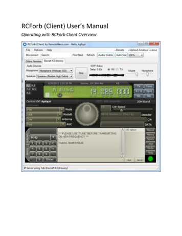
Example observationThe following figure is an example 2-minute observation (when the galactic plane is in the beam ):Fig. 9: Example observation. Top left: Averaged Spectrum, top center: Calibrated Spectrum, topright: Dynamic Spectrum (Waterfall), bottom: Time series (Power vs Time plot).The top left plot is the averaged spectrum , showing the average power (intensity) for everyfrequency. The top center plot is the calibrated spectrum , which is identical to the averagedspectrum, with the effects of the receiver removed (so the noise floor becomes flat and the peaksbecome more distinct). The top right plot shows the dynamic spectrum (waterfall) (a Power vsFrequency vs Time graph displayed as a 2D plot with a colormap indicating Power) and thebottom plot shows the average power vs time plot. The calibrated spectrum plot is usuallysufficient for beginner observers.We see three curvy bumps in the averaged spectrum . This is due to the receiver’s bandpassshape (different sensitivity at each frequency) and should not be mistaken for radio emissions11
(this is why we should refer to the calibrated spectrum : to account for the receiver’s instabilities,imperfections, effects etc.).As you can see, there are three distinct peaks on the calibrated spectrum at around 1420.5,1420.7 and 1420.85 MHz . This is the hydrogen line, and it’s blueshifted (frequency 1420.4 MHz),meaning the source is approaching us ! We’ve just detected 3 unique spiral arm of our owngalaxy , and by conducting another observation (i.e. when the other side of the Milky Way is in thebeam), we should expect to see differently Doppler-shifted line(s), potentially indicating morespiral arms, Doppler-shifted (redshifted or blueshifted) to a different degree. From a 2-minuteobservation with VIRGO , we’ve just proven that beyond any doubt, we do indeed live in a spiralgalaxy !Using a few simple Doppler shift equations you are also encouraged to find the velocity of thedetected spiral arms relative to Earth.ConclusionI hope this document has introduced you to the majesty of the radio sky and guided youregarding the construction of your first radio telescope. If you’d like to learn more about radioastronomy, the following resources are highly recommended: Mapping the Galaxy with Radio Astronomy: https://youtu.be/-UrzmAa62hoRadio Astronomy in Five Minutes: https://youtu.be/3EcrrLNlWdENational Radio Astronomy Observatory (NRAO): https://public.nrao.edu/radio-astronomy/The Hydrogen 21-cm Line: /h21.htmlWhat is Radio Astronomy - everyone/radio-astronomy/index.htmlIf you have any questions, feedback, suggestions or anything else you’d like to contact the authorabout, feel free to email me at 0xcoto@protonmail.com and I’ll be happy to get back to youshortly!12
Image attribution noticeThis article uses material from the Wikipedia article "Electromagnetic spectrum" , which isreleased under the Creative Commons Attribution-Share-Alike License 3.0 .13
Building our radio telescope Our radio telescope will consist of a p arabolic antenna (e.g. satellite TV dish) with a f eedhorn optimized for 1420 MHz, an app